What is an Ampere?
By William Conklin, Associate Editor
An ampere is the standard unit for measuring electric current. It describes how much electric charge moves through a conductor over time and provides a practical way to quantify current flow in electrical and electronic systems.
Overview: What is an Ampere?
Electric current is the movement of charged particles, usually electrons, through a circuit. When current flows, energy is delivered to devices such as lights, motors, heaters, and electronics. The ampere provides a universal scale for describing this movement, allowing designers and operators to determine how circuits will perform under different electrical conditions.
In more advanced electrical theory, current can also be analyzed using idealized models. For example, straight parallel conductors are sometimes treated as conductors of infinite length with a negligible circular cross-section. These simplified parallel conductors of infinite extent allow examination of fields and forces without edge effects. At this level, current is viewed as the flow of discrete particles, each carrying an elementary charge, and the total flow is expressed in coulombs, the standard unit of electric charge passing a point in a given time interval.
Scientific Definition and Formula
From a physics perspective, one ampere is the rate of flow of one coulomb of charge per second through a point in a circuit. This direct relationship between charge and time makes the ampere a foundational quantity in electrical science. It is defined in the SI system as the SI base unit for current.
In practical circuit analysis, current is most often calculated rather than measured directly. Ohm’s Law describes the relationship between current, voltage, and resistance:
I = V / R
Where I is the current, V is the electrical voltage, and R is the resistance. This relationship shows that current increases when voltage rises or when resistance decreases, understanding how voltage, resistance, and current interact is essential for predicting circuit behaviour and ensuring safe operation.
Electromotive Force and Charge Flow
Current does not move on its own; it requires a source of energy. Electromotive force, commonly produced by a battery or generator, provides the push that moves charge through a circuit. EMF describes the energy supplied per unit charge and is closely related to electrical voltage, though the two terms have different formal definitions. Together, voltage and EMF explain why current flows, how energy is transferred, and how devices convert electrical energy into work.
Measuring Electric Current
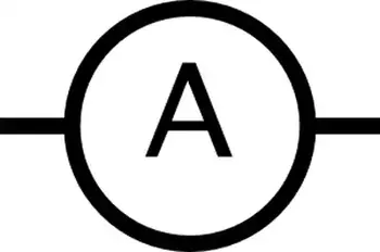
Electric current is measured using an instrument called an ammeter. An ammeter is connected in series with a circuit so that all current passes through the meter. Although current is measured in coulombs per second, ammeters are calibrated in amperes because amperes are more convenient for real-world applications.
Current values can vary widely. Electronic devices may operate at microamperes or milliamperes, while industrial equipment may operate at kiloamperes. This broad range is why SI prefixes are applied to the base unit. Engineers also use watt volt calculations to relate current and voltage to electrical power, connecting circuit measurements to real energy use. Exploring power factor reveals how reactive energy and real power interact in systems with large currents.
Amperes and Electrical Safety
Current level is a critical factor in electrical safety. The effect of electricity on the human body depends largely on the amount of current flowing and the path it takes.
Very small currents may only be felt as a mild sensation, while higher currents can cause muscle contraction, breathing difficulty, or cardiac disruption. Currents on the order of tens of milliamperes can be dangerous, and currents around 100 milliamperes may be fatal if they pass through the chest. Moisture, contact duration, and body resistance all influence risk. Reading about electricity safety shows why even small currents, measured in amperes, can pose serious hazards.
Because of these dangers, electrical standards place strict limits on allowable current levels and require protective devices to interrupt current before injury occurs. An ammeter is essential for measuring current directly in amperes within a circuit.
Practical Applications of Amperes
Amperes play a central role in the design and operation of electrical systems. Wire sizes are selected based on how much current they must safely carry. Circuit breakers and fuses are rated in amperes to ensure they open when current exceeds safe limits. Electronic components specify maximum current ratings to prevent damage.
In everyday examples, a typical household light bulb draws about 1 ampere, while appliances such as electric irons or heaters may draw 10 amperes or more. Whole-house electrical demand varies throughout the day and can range from a few amperes to several dozen amperes, depending on appliance usage.
At the other extreme, modern electronic devices can operate using tiny currents measured in microamperes or even nanoamperes. This efficiency allows batteries in clocks, sensors, and portable electronics to last for years. Learning about the watt helps readers see how power (watts) relates to current (amperes) and voltage.


Why the Ampere Matters
What is an ampere? The ampere is more than a unit of measurement. It is a key concept that links electrical theory to real-world practice. By understanding how current is defined, measured, and controlled, engineers can design safer systems, technicians can troubleshoot problems more effectively, and users can better appreciate the invisible flow of charge that powers modern life. From idealized models of infinite-length conductors to everyday applications in homes and industries, the ampere remains the essential bridge between electrical science and practical technology.
Related Articles

