Electricity Power Explained


Electricity power underpins voltage, current, and wattage in generation, transmission, and distribution across the grid, integrating AC/DC systems, transformers, generators, load management, power factor correction, and renewable energy for efficient, reliable supply.


What Is Electricity Power?

Electricity power is energy transfer rate: voltage times current, yielding watts in AC/DC systems.

✅ P = V * I; apparent, real, reactive power relationships

✅ Power factor improves efficiency and reduces I^2R losses

✅ Transformers step voltage for transmission efficiency


The make up of the electricity power sector has been in transition over recent history. In most provinces, there has been a transition from traditional electric utilities (which are mostly provincially-owned crown corporations) to private generation, transmission and distribution assets. For context, industry overviews such as electricity generation in Canada outline how policy and market structures influence capacity additions today.

In 2014, Canadian eutilities and industrials generators produced more than 639 terawatt hours of electricity. When it comes to hydroelectric power, Canada is the world's second largest producer. Hydroelectricity accounts for 59.3 per cent of Canada’s supply. Other energy sources that contribute to the transfer of energy include: coal, uranium, natural gas, petroleum and non-hydro renewable energy sources. About 67 per cent of Canada’s energy comes from renewable sources like wind, solar and hydroelectric power stations and 82% from non-greenhouse gas emitting sources. A breakdown of major fuels is available through sources of electricity for readers comparing provincial mixes.

Hydropower output is intrinsically linked to water availability and operations, and resources on water and electricity explain how hydrology and infrastructure shape generation profiles.

In 2014, almost 59 terawatt hours of electricity exported to the USA, while about 13 terawatt hours was imported from the United States. These trade patterns reflect how provinces balance load and generation portfolios, as noted in discussions of electricity supply dynamics under varying market conditions.

Canada's industrial sector is responsible for the largest share of electricity demand because there are a number of energy-intensive industrial activities like mining, oil and gas production, pulp and paper production, and other primary industry uses. Residential and commercial sectors consume much smaller quantities of electricity for lighting (light bulb), heating, and communications. Detailed consumption patterns can be explored in Canada's electricity demand by sector and region.

R&D programs aimed at maintaining the operating capability of the nation’s existing nuclear power plants and developing the next generation of nuclear technologies. Nuclear energy is the world’s largest source of emission-free electricity power. The Nuclear Energy program is working to develop cost-efficient technologies that further enhance nuclear safety, minimize the generation of nuclear waste, and further reduce the risk of proliferation. Within the broader generation portfolio, resources like nuclear are profiled in guides on how electricity is generated across different technologies.

To meet the rising demand of the 21st century, significant improvements in America’s electric system are necessary. Blackouts serve as a powerful reminder of the critical role electricity plays in the everyday lives of people.


Voltages, currents, power energy

When it comes to electric current, electrical voltage, electric circuit dynamics and energy powers, all rely on the flow of the electron. What this means is that power voltage feeds loads, solid state power load devices, and other loads that need electric power. Electric power is the rate at which that power is measured in watts or voltage in volts. There are various forms of energy measured in si unit: apparent power, reactive power, ac power, real power in watts, etc. For a refresher on fundamental concepts and terminology, see what is electricity to connect these quantities with practical applications.

Electrical Engineers and Scientists alike seek common views in order to develop new technologies for the storage of energy and the transmission of electric potential through power circuits that will contribute to energy efficiency of the electric industry. For instance, the copper wires used in typical transmission lines lose a percentage of the electricity passing through them because of resistance over long distances, which causes the wires to heat up. But "superconducting" materials have no resistance, and if they are used to transmit electricity in the future, very little of the electricity will be lost.


Related Articles

Related News

Definition of a Rectifier

Definition of a rectifier explains AC to DC conversion using diodes, bridge or full-wave circuits, filters, and regulators to supply stable DC, reduce ripple, and power electronics, chargers, and DC motor drives.


What Is the Definition of a Rectifier?

An explanation of devices that convert AC to DC using diodes and filtering to deliver regulated, low-ripple DC power.

✅ Converts alternating current to direct current via diodes

✅ Topologies: half-wave, full-wave, bridge rectifier

✅ Uses filters and regulators to minimize ripple and stabilize DC


Understanding the definition of a rectifier is fundamental to grasping the complexities of power electronics and electrical engineering. Rectifiers are pivotal in converting AC power to DC power, a critical process for operating numerous electronic devices. By delving into the intricacies of half-wave, full-wave, and bridge rectifiers, as well as the silicon-controlled rectifier, it becomes clear that these devices are crucial in shaping the modern world of electronics. For readers new to the basics, an overview of the difference between AC and DC can clarify foundational concepts.


In electrical engineering, the definition encompasses a vital device that plays a crucial role in converting alternating current (AC) into direct current (DC). It  is an essential component in power electronics. It facilitates the conversion of AC power, commonly used in households and businesses, to DC power that electronic devices rely on. To contextualize this conversion, understanding alternating current behavior in typical distribution systems explains the need for rectification.

They come in various forms, such as diodes, mercury arc valves, and silicon-controlled rectifiers (SCRs). A diode, the most basic rectifying component, allows current to flow in only one direction. This feature helps convert AC power, which alternates direction, to DC power that flows in a single, continuous direction. For measurement and notation conventions, see how DC current is defined and applied in circuit analysis.

AC to DC conversion regulates voltage to create a steady and reliable energy supply. Throughout this conversion, rectifiers often assume different configurations depending on the specific application or requirement. Two popular configurations are the half-wave rectifier and the full-wave rectifier. Downstream stabilization is often handled by a voltage regulator that smooths residual ripple and safeguards loads.

A half-wave type allows only one half of the AC waveform to pass through while blocking the other half. This type is relatively simple and cost-effective but has a few downsides, such as lower efficiency and increased ripple voltage. Ripple voltage refers to the residual periodic variation of the DC output voltage. The result is an unsteady DC output, which might be undesirable in certain applications.

On the other hand, the full-wave type allows both halves of the AC waveform to pass through, effectively doubling the output frequency and reducing the ripple voltage. This configuration improves efficiency and provides a smoother, more consistent DC output voltage. The full-wave type has two primary forms: the center-tap configuration and the bridge rectifier.

The bridge rectifier is a highly efficient configuration that uses four diodes in a specific arrangement. This configuration eliminates the need for a center-tapped transformer, a key component in center-tap full-wave rectifiers, thus reducing overall size and cost. In addition, the bridge rectifier provides better voltage regulation and reduced harmonic distortion, making it ideal for various applications. For consistent terminology across datasheets, reviewing key electricity terms can prevent misinterpretation during design.

They serve numerous purposes in various fields. For instance, they are used in power supply circuits of electronic devices, battery chargers, and welding equipment. In addition, they help in voltage regulation for DC power supplies and extract radio signals from transmitted modulated signals. Many of these uses depend on stable direct current characteristics to ensure predictable device behavior.

Silicon-controlled rectifiers (SCRs) represent a more advanced type of rectifier. As silicon-based semiconductor switches, SCRs can control large amounts of current with a small input signal. This ability to manage current flow in a controlled manner sets SCRs apart from regular rectifiers, like diodes. As a result, SCRs are often used in power control applications, such as motor speed controllers, light dimmers, and temperature regulators.

Understanding how rectifiers play a pivotal role in industries and everyday applications is essential. One such application is in electric vehicles (EVs), where rectifiers contribute to charging systems by converting AC power from the grid to DC power for charging the battery. Additionally, they are utilized in renewable energy systems, like solar power and wind power, to convert the harvested energy into a stable and usable form for various applications. At a broader level, a concise electricity definition helps frame how conversion stages integrate with generation, storage, and loads.

Another application is in telecommunications equipment, where they help maintain a continuous and stable power supply. In the aviation and marine industries, rectifiers ensure sensitive equipment operates with minimal interference from fluctuating power sources. Moreover, they are employed in power supply units of medical devices, computers, and other critical equipment that demand stable power supplies.


How does it work in AC to DC conversion?

Its primary function is to convert AC voltage, which periodically reverses direction, into DC voltage, which flows in one direction. Its simplest form it consists of a diode, which allows current to pass in only one direction. When connected to an AC power source, the diode rectifies the current by blocking the negative half-cycles of the AC waveform. More advanced configurations, like full-wave rectifiers and bridge rectifiers, rectify both the positive and negative half-cycles, increasing efficiency and providing a smoother output.


What are the differences between half-wave and full-wave rectifiers?

The key difference between half-wave and full-wave rectifiers lies in their efficiency and output. A half-wave type only allows one-half of the AC waveform to pass through, blocking the other half. As a result, it has lower efficiency, increased ripple voltage, and produces an unsteady DC output.

On the other hand, a full-wave type allows both halves of the AC waveform to pass through, leading to increased efficiency and reduced ripple voltage. In addition, the full-wave type produces a smoother, more consistent DC output voltage, making it more suitable for applications that require a stable power supply. The full-wave type can be implemented using a center-tap or bridge rectifier configuration.


Related Articles

View more

Electricity Supplier - Make The Right Choice

Electricity supplier delivers power via transmission and distribution networks, managing tariffs, load forecasting, SCADA, and power quality, integrating renewables, smart meters, and demand response to ensure grid reliability, compliance, and efficient kWh billing.


What Is an Electricity Supplier?

An electricity supplier procures and delivers power, manages tariffs, and ensures grid reliability and power quality.

✅ Energy procurement and wholesale market participation

✅ Distribution coordination, SCADA monitoring, and outage management

✅ Tariff design, metering, billing, and power quality compliance


Who is my electricity supplier?

In Canada and the United States, it’s easy to learn which energy provider serves your property or residence. It depends on whether you are trying to find your electricity and natural gas supplier. Sometimes, homes and businesses have the power to choose their energy service utility company and the products and service they provide. Customers are free to choose. It's a competitive energy marketplace. For a plain-language primer on infrastructure, see the electricity supply overview to understand typical delivery steps.

If you use both services, your property might have the same local distribution company for both fuels, – commonly known as a "duel fuel supplier". But if your utility records are stored separately, you might need to more research to learn who supplies your natural gas services and your electricity services separately. If you are curious where the power originates, this guide to how electricity is generated explains common fuel sources and grid integration.


Here is a list of accredited Electricity Suppliers in Canada

https://www.ic.gc.ca/eic/site/mc-mc.nsf/eng/lm00525.html

Market dynamics can vary by province, and recent electricity demand trends in Canada help explain seasonal shifts in offers.


Here is a list of accredited Electricity Suppliers in the United States.

https://www.electricchoice.com/blog/25-top-providers-part-1/

When comparing providers, consult current electricity price benchmarks to contextualize quoted rates.


Who can supply electricity?

All electricity supplier companies must have a licence from the Office of Gas and Electricity Markets (Ofgem). One of the licence conditions is that a  company must produce codes of practice on:

Although the codes of practice are not legally enforceable, they will be useful when negotiating with a company and any breach should be reported to governmental regulatory authorities. Understanding the basics in this introduction to what electricity is can make those obligations clearer.


Choosing an electricity supplier

You can change your company if you wish. If you are considering changing your company you should be aware that the pricing structures, services offered and policies will differ between the different companies.You should carefully check the information and contracts of the competing electricity suppliers, and compare these to your current terms, to make sure that you choose the best deal for your needs. A lot depends on your gas bills or electricity bill, and your location by postal code. You can also estimate bill impacts by applying tips from this guide on how to save electricity while comparing plans.


Dual fuel offers

Dual fuel is the supply of gas and electricity by the same company. Some gas and electricity suppliers are licensed separately by Ofgem to supply customers with both fuels. Some companies will supply both fuels under one contract, while others will give one contract for gas and another for electricity. For households with high usage, reviewing your typical electricity power consumption patterns can reveal whether dual fuel makes financial sense.

Electricity Suppliers who make dual offers will often give a discount off the total bill as they can make administrative savings by issuing combined bills and collecting combined payments. However, this does not necessarily mean that the cost of gas and electricity

  • procedures for complaints
  • payment of bills, arrangements for dealing with arrears and prepayment meters
  • site access procedures
  • energy efficiency advice
  • services for older, disabled and chronically sick people. As part of this code of practice, the company must keep a register of these people and provide services to help those who are blind and partially sighted or deaf or hearing impaired. Especially during a power outage, it is important that these customers are restored asap.The customer may have to pay for some of these services.
    • how you will be charged for your electricity supply. Some companies may make a fixed standing charge and then a unit charge for the amount of electricity used; an company may not make a standing charge, but charge a higher unit price
    • whether different charges apply to different periods during the day
    • if cheaper prices are offered for particular payment methods, for example, if you pay by direct debit
    • what service standards each company is offering, for example, for repairs, extra help for older or disabled customers.All electricity suppliers must keep a list of their customers who ask to be identified as pensioners, chronically sick or disabled.The electricity supplier must tell all its customers that it keeps such a list and give information on how customers can be added to the list
    • the company's policies, for example, on debt and disconnection.


Related Articles

View more

Resistance Formula Explained

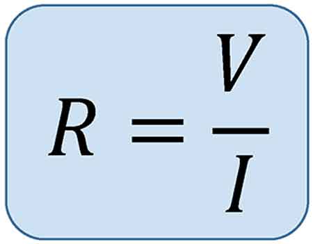
The resistance formula, R = V/I, shows how voltage and current determine opposition in a circuit. Central to Ohm’s Law, it is widely applied in electronics, power distribution, and engineering to calculate resistance, ensure efficiency, and design reliable electrical systems.


What is a Resistance Formula?

The resistance formula is a vital tool in understanding and optimizing electrical circuits. By analyzing the interplay between Ohm's law, conductor material, wire length, cross-sectional area, and temperature, we can manipulate Resistance to improve circuit performance. Balancing these factors ensures the efficient flow of electrons, minimizes energy loss, and maximizes the effectiveness of our electrical devices.

✅ R = V/I links voltage, current, and resistance

✅ Essential for circuit analysis and design

✅ Applied in electronics, power systems, and physics


Electrical circuits are essential for powering our daily lives, and understanding the factors that influence their performance is key to optimizing their efficiency. A critical aspect of electrical circuits is the Resistance they encounter, which directly affects the flow of electrons. Based on Ohm's law, the formula helps us analyze and manipulate various elements within a circuit. Topics like electrical resistance and the unit of electrical resistance expand on how opposition to current flow is measured and applied in engineering.

The flow of charge in any conductor depends on material properties and circuit design, where individual resistances combine differently depending on series or parallel circuit arrangements. According to law resistance principles, the total parallel resistance is always less than the smallest branch, and values are measured as resistance in ohms. Materials with the smallest resistivities like copper conduct efficiently, though their performance is affected by the temperature coefficient of resistivity, which alters conduction as heat rises. For visual examples and diagrams, resources such as Wikimedia Commons provide helpful illustrations.


Ohm's Law

Ohm's law is fundamental to understanding electrical circuits. It states that the Voltage across a conductor is directly proportional to the electric Current passing through it, and the constant of proportionality is the electrical Resistance. In mathematical terms, Ohm's law can be expressed as V = IR, where V is the Voltage, I is the electric Current, and R is the Resistance. Related principles, including Ampere’s Law and the Biot-Savart Law, further explain how current and magnetic fields interact with resistance in circuits.

The formula R = ρ(L/A) is derived from Ohm's law and describes how R depends on the conductor's material, length (L), and cross-sectional area (A). The resistivity (ρ) is a property unique to the conductor material and represents its ability to impede the flow of electrons. Different materials, such as copper or aluminum, have different resistivities, affecting the overall electrical R.

Wire length and cross-sectional area play a significant role in determining a conductor's R. As the wire length increases, so does the R, as electrons face more obstacles. Conversely, increasing the cross-sectional area reduces R, allowing more electrons to flow through the conductor simultaneously. This inverse relationship between R and cross-sectional area is vital in designing circuits to minimize energy loss and optimize efficiency.


Various factors influence the resistivity of conductor material. For instance, impurities in the material can hinder electron flow, thereby increasing resistivity. Additionally, the arrangement of atoms within the material's lattice structure affects the ease with which electrons can pass. Finally, the temperature coefficient is crucial, as fluctuations can alter resistivity. Generally, R increases with higher temperatures as atoms vibrate more and impede electron flow.

Resistance and conductance differ in their relationship to the flow of electrons. While R quantifies the opposition a conductor presents to the flow of electrons, conductance represents the ease with which electrons can pass. Mathematically, conductance (G) is the reciprocal of Resistance (R), and is measured in Siemens (S):

G = 1/R

The formula can be used to calculate power dissipation in a circuit. Power (P) is the product of Voltage (V) and current (I): P = VI. Using Ohm's law, we can substitute V = IR into the power formula to obtain P = I^2R. This equation demonstrates that higher R results in greater power dissipation, manifesting as heat. Hence, managing R is essential in preventing energy loss and maintaining circuit efficiency.

Ohm's law defines a mathematical relationship involving V, R, and current (I) within an electrical component. Ohm, denoted by the Greek letter omega (Ω), is the unit of measurement for R. Furthermore, Ohm's law can derive a power equation by computing electrical power, quantified in watts. Subsequently, Gustav Kirchhoff built upon Ohm's foundational work and introduced Kirchhoff's rules, two equalities addressing current and Voltage in an electric circuit model.

Ohm's law outlines the fundamental principles of electrical circuits, highlighting the interdependence between voltage, current, and resistance. This relationship can be expressed in three different formulas:

V = I × R (Voltage equals Current multiplied by Resistance)
R = V / I (Resistance equals Voltage divided by Current)
I = V / R (Current equals Voltage divided by Resistance)

These formulas illustrate the interconnection of voltage, current, and resistance in electrical circuits. By manipulating these relationships, we can analyze the behaviour of circuits, troubleshoot issues, and optimize efficiency.

The significance of Ohm's law extends beyond its mathematical representation. It forms the basis for understanding various electrical phenomena, including power dissipation, energy consumption, and the impact of R on the performance of electrical components. The role of resistance is closely tied to capacitance and inductance, which determine energy storage and reactance in alternating current systems.

As we explore the vast applications of electrical circuits, understanding the formula allows us to make informed decisions in choosing conductor materials, adjusting wire length and cross-sectional area, and considering temperature fluctuations. With an understanding of how these factors interact, we can continue to innovate, create, and harness the power of electricity to achieve a brighter future.


Related Articles


View more

Electricity Supply And Demand Balance

Electricity supply covers generation, transmission, distribution, grid infrastructure, voltage regulation, frequency control, power quality, protection, SCADA, and load management to ensure reliable energy delivery to industrial, commercial, and residential loads.


What Is Electricity Supply?

Electricity supply is generation, transmission and distribution of power with set voltage, frequency and reliability.

✅ Involves generation, HV transmission, MV/LV distribution networks

✅ Ensures voltage regulation, frequency control, and power quality

✅ Uses SCADA, protection relays, and load forecasting for reliability


What Is Electricity Supply?

Electricity Supply is a complex balanced system of electric power generation and real time customer demand. Production (supply) and consumption (demand) dictate electricity pricing in the United States and Canada.  For a regional view, the analysis at Electricity Demand in Canada highlights how seasonal peaks and resource availability shape prices.

Where does the term "electricity supply" originate? How does that supply move from one point to another? These are most important questions to ask when you want to understand the electric power industry.

If you're new to the vocabulary, the concise glossary at Electricity Terms can clarify definitions used throughout the industry.

The first thing to know is that electric power is generated in the United States and Canada in power plants which house electrical generators. Then, power is transported (transmission and distriubtution) through the power grid to the customer. This complex network of transmission lines delivers power to industrial, commercial, institutional and residential customers. For a step-by-step overview of system operations, Electricity: How It Works explains generation, transmission, and distribution in practical detail.

In the electricity industry, transmission and distribution wires do the work of transporting power to satisfy electricity demand during real time peak demand. This is the job of the electricity market. The natural gas and fossil fuels industry works in the same way. These lines run from generating station to substations (sometimes over great distances, like in the case of British Columbia and Manitoba where generation is in the far north and the consumption is in the south. This is where the voltage is reduced for local consumption. Substations are usually located close to where the electricity is consumed. 

For background on core power concepts, the primer at Electricity Power connects voltage, current, and load to real-world grid behavior.

The various prices of electricity depends on the electricity supply mix and the energy efficiency of the customer. Electricity energy supply is usually measured in terawatt hours.

The system design is of three-phase alternating current electrical generation and distribution, which was invented by Nikola Tesla in the 19th century. He considered that 60 Hz was the best frequency for alternating current (AC) power generating Electricity Supply. He preferred 240 V, which was claimed to be better for long supply lines. Thomas Edison developed direct current (DC) systems at 110 V and this was claimed to be safer. For more information about the early battles between proponents of AC and DC supply systems see War of Currents. For foundational fundamentals beyond this history, the overview at What Is Electricity clarifies the principles common to both AC and DC systems.

The German company AEG built the first European generating facility to run at 50 Hz, allegedly because the number 60 did not fit into the numerical unit sequence of 1, 2, 5…. At that time, AEG had a virtual monopoly and their standard spread to the rest of the continent. In Britain, differing frequencies (including 25 Hz 40 Hz and DC) proliferated, and the 50 Hz standard was established only after World War II.

To see how frequency standards interact with generation and end-use performance, the explainer at How Electricity Works ties design choices to everyday operation.

Originally much of Europe was 110 V too, just like the Japanese and the US system today. It was deemed necessary to increase the necessary voltage to draw more electrical power with reduced energy loss and voltage drop from the same copper wire diameter.

The choice of utilization voltage is governed more by tradition than by optimization of the distribution system. In theory, a 240 V distribution system will use less conductor material to deliver a given quantity of power. Incandescent lamps for 120 V systems are more efficient and rugged than 240 V lamps, while large heating appliances can use smaller conductors at 240 V for the same output rating. Practically speaking, few household appliances use anything like the full capacity of the outlet to which they are connected. Minimum wire sizes for hand-held or portable equipment is usually restricted by the mechanical strength of the conductors. One may observe that both 240 V system countries and 120 V system countries have extensive penetration of electrical appliances in homes. National electrical codes prescribe wiring methods intended to minimize the risk of electric shock or fire. For household applications, home electricity basics show how these voltage considerations affect outlets, circuits, and safety practices.

Areas using (approximately) 120V allow different combinations of voltage, suitable for use by a variety of classes of electrical equipment.


Related Articles

View more

Prospective Fault Current Meaning Explained

Prospective fault current (PFC) is the highest electric current that can flow in a system during a short circuit. It helps determine equipment ratings, breaker capacity, and safety measures in electrical installations to prevent overheating, fire, or component failure.


What is the Meaning of Prospective Fault Current?

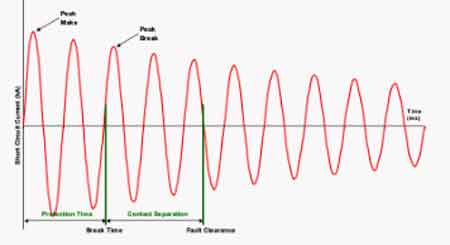
Prospective fault current refers to the maximum current expected during a short circuit at any point in an electrical system.

✅ Helps size circuit breakers and fuses for safe disconnection

✅ Ensures compliance with installation and safety codes

✅ Prevents equipment damage from excessive short-circuit current

Prospective fault current (PFC) is a key factor in the safety and design of electrical systems. It represents the maximum current that could flow in the event of a fault, such as a short circuit. Understanding PFC is essential for selecting protective devices that can handle fault conditions safely. This article explores what PFC is, how it is measured, and its importance for electrical installations, while addressing key questions. Understanding electrical short circuits is key to calculating prospective fault current and ensuring system safety.

When measuring prospective short circuit current in an electrical system, it’s essential to perform tests between L1 N CPC and L2 N CPC to assess the fault current across different phases and protective conductors. These measurements help identify the maximum prospective fault current present in the system, especially at points involving live conductors. Whether taking note of a single-phase supply or between line conductors on a three-phase supply, proper testing protocols must be followed. Technicians should always use insulated test leads rated for the expected voltage and current levels, and please refer to the test meter manufacturer’s instruction for safe and accurate operation. Reliable results ensure that the protective devices can safely interrupt fault conditions, preventing system damage and ensuring compliance with fault current protection standards.


Frequently Asked Questions

Why is it Important?

Prospective fault current refers to the maximum current that could pass through a system during a fault. The PFC helps determine the breaking capacity of fuses and circuit breakers, ensuring these protective devices can handle high currents safely. This is vital for protecting the electrical installation and those working near it.

Understanding PFC is critical for ensuring increased safety for employees and third parties. Protective devices must be selected to handle PFC; otherwise, they may fail to operate correctly, leading to severe consequences, such as fires or injuries. To fully grasp how PFC affects energy flow, it’s useful to review the concept of electrical resistance in a circuit.


How is Prospective Fault Current Measured or Calculated?

PFC can be measured or calculated using tools such as a multifunction tester, often during fault current testing. The instrument uses a single-phase supply or between line conductors on a three-phase supply to measure the maximum potential current at various points in the installation. Testing often involves checking currents between L1 N CPC, L2 N CPC, and L3 N CPC, which measure current between the lines to neutral in a three-phase system.

When performing these tests, technicians should follow regulation 612.11 of a single-phase supply or between line conductors on a three-phase supply, ensuring that simple and circuit protective conductors are all connected correctly. Accurate testing must also account for maximum current flow. Live testing requires extreme caution, and it is important to refer to the test meter manufacturer’s instructions to ensure proper usage and safety. In three-phase systems, 3-phase electricity significantly impacts how fault current behaves during a short circuit.


What is the difference between PFC and Short-Circuit Current?

Though often confused, prospective fault current and short-circuit current are distinct. Prospective fault current is the theoretical maximum current that could flow in a fault, used to predict the worst-case scenario for selecting protective devices. Short-circuit current refers to the actual current that flows during a fault, which depends on real-time conditions such as circuit impedance. Prospective fault current is one of the many concepts that form the foundation of electricity fundamentals.


How Does Prospective Fault Current Impact the Selection of Protective Devices?

The calculation of PFC plays a critical role in selecting the correct protective devices. Circuit breakers and fuses must have a breaking capacity that matches or exceeds the prospective fault current in the system. If the PFC exceeds the breaking capacity, the protective device may fail, leading to dangerous electrical hazards.

For instance, fault current testing using a multifunction tester between phases and neutral (L1, L2, L3) ensures that protective devices are rated to handle the highest potential fault current in the system. Proper circuit protection ensures that the system can interrupt faults safely, minimizing the risks to workers and equipment.


What Standards and Regulations Govern Prospective Fault Current Calculations?

Various standards, such as IEC 60909, govern how PFC is calculated and how protective devices are selected. These regulations ensure that electrical systems are designed to handle maximum fault conditions safely. Regulation 612.11 further specifies how live testing should be conducted using proper equipment and safety protocols.

It is essential to test PFC at relevant points in the system and follow testing standards to ensure compliance and safety. Devices selected based on PFC calculations help ensure that electrical systems can withstand faults and maintain reliable operation.

Prospective fault current is a crucial element in the safety and reliability of electrical installations. By calculating PFC, engineers can select protective devices that ensure safe operation in the event of a fault. Testing for fault currents at different points in the system and adhering to regulations are essential steps in preventing hazardous conditions.

By choosing protective devices with the appropriate breaking capacity and following safe testing practices, electrical installations can handle fault conditions and protect both workers and equipment from harm. Selecting protective devices that match the PFC is essential for reliable electric power systems design.


Related Articles


View more

Alternative Electricity Key To Carbon Reduction

Alternative electricity integrates renewable energy, smart grids, and distributed generation, combining solar photovoltaics, wind power, hydropower, and battery storage with power electronics and demand response to decarbonize grids and improve reliability.


What Is Alternative Electricity?

Alternative electricity uses renewables, storage, and smart grids to deliver reliable, low-carbon power.

✅ Power electronics enable PV, wind, and storage grid integration

✅ Smart inverters support voltage, frequency, and reactive power control

✅ Microgrids improve resilience with islanding and load management


Alternative electricity power is essential if we are to find affordable and workable sources of energy before the world completely consumes its limited supply of energy sources. Many countries have started to introduce renewable energy schemes and many countries have invested money into researching and even producing different sources of electricity energy. While it is essential that we become less reliant or not reliant at all on fossil fuels, many forms of alternate energy have their disadvantages as well as their obvious advantages. The advantages of alternate energy far outweigh the disadvantages. For a primer on how modern grids convert primary energy into usable power, see this overview of how electricity is generated across different technologies today.


Wind Energy

Harnessing the power of the wind and using it to our ends is hardly a new idea. Windmills have been and still are used for many different purposes and have been for a great many years, but the improvement of turbines combined with the improved technology to turn the motion of turbine blades into an energy source has seen a marked increase in the use of electricity generating turbines. Detailed diagrams explain how turbine blades capture kinetic energy to generate electricity efficiently under varying wind speeds.

Wind power is very popular, but in order to provide a reasonable amount of power it may prove necessary to have large amounts of turbines. On windy days, and even not so windy days some turbines make a noise that many residents consider to be unbearable. Areas of open countryside are protected by conservation orders, which means they can’t be built there either and if there is no conservation order there are still protestors willing to do almost anything to stop the turbines being built. The only viable option left is to use offshore wind farms and these are being investigated, developed and planned all around the world but it takes too many turbines to create a reasonable amount of power and eventually they will have to be built inland; a matter that will be contested wherever the wind farms are proposed to be built.

Understanding capacity factors and grid integration is key to planning electricity production that balances reliability and community impacts.

Wind power is produced by converting wind energy into electricity. Electricity generation from wind has increased significantly in the United States since 1970. Wind power provided almost 5% of U.S. electricity generation in 2015. These trends mirror broader shifts in electricity generation portfolios as states pursue renewable portfolio standards.


Solar Energy

Solar energy is probably the most common form of alternate energy for everyday people and you can see solar lights ad other solar accessories in many gardens. Governments are beginning to offer grants to assist in paying for photovoltaic roof tiles; these tiles are easily fitted onto your roof and collect the heat from the sun. This heat can either be used to heat water or can even be converted into energy electric power. The advantage for the consumer is that by including a grid tie system you can actually sell unused energy back to the grid. Photovoltaic tiles take the place of ordinary roof tiles and can be perfectly blended to fit the look of the outside of your house. With solar energy you too can help the environment.

Many utilities now offer tariffs that credit exports from rooftop systems, linking household budgets to green electricity choices in a transparent way.

Solar power is derived from energy from the sun. Photovoltaic (PV) and solar-thermal electric are the two main types of technologies used to convert solar energy to electricity. PV conversion produces electricity directly from sunlight in a photovoltaic (solar) cell. Solar-thermal electric generators concentrate solar energy to heat a fluid and produce steam to drive turbines. In 2015, nearly 1% of U.S. electricity generation came from solar power. PV and solar-thermal now sit alongside other major sources of electricity in utility planning models.


Biomass

Ask most people which renewable energy source is the most widely used and they would say either wind or solar, but they’d be wrong or at least they certainly would in America. Since 2000 Biomass has been the most highly produced alternate energy in the United States. Using plant and animal material to create energy isn’t without its downfalls. It would almost certainly meet with competition from residents if biomass power stations were to be created in built up areas. The decomposing plants and animal waste creates an awful smell that is incredibly difficult to mask but it is very renewable (there’s always plants and animal waste).

Biomass is material derived from plants or animals and includes lumber and paper mill wastes, food scraps, grass, leaves, paper, and wood in municipal solid waste (garbage). Biomass is also derived from forestry and agricultural residues such as wood chips, corn cobs, and wheat straw. These materials can be burned directly in steam-electric power plants, or they can be converted to a gas that can be burned in steam generators, gas turbines, or internal combustion engine-generators. Biomass accounted for about 2% of the electricity generated in the United States in 2015.


Other renewable energy sources

These are the main three renewable energy sources that the countries of the world are creating at the moment but there are others. Whether nuclear power is a viable alternate or not is a debate that will undoubtedly rage on forever, but it is a renewable energy and some countries already have extensive capabilities to produce it. Modern technology means that nuclear power stations are safer than they’ve ever been and damage to people, animals or plantation is highly unlikely. However, it takes a long time to develop nuclear power station and even plants that are already being built may take ten years to come to fruition.


Renewable energy sources provide 13% of U.S. electricity

Hydropower, the source of about 6% of U.S. electricity generation in 2015, is a process in which flowing water is used to spin a turbine connected to a generator. Most hydropower is produced at large facilities built by the federal government, like the Grand Coulee Dam. The West has many of the largest hydroelectric dams, but there are many hydropower facilities operating all around the country. For a deeper look at how turbines and dams convert flow into water electricity, engineers often study case histories from multiple river systems.

Hydro power is used in some countries and uses the motion of waves to create energy. While it is a possibility, the amount of energy produced is minimal and the outlay to set these schemes up is quite large. Without further investigation and improvement in the techniques used it is unlikely that Hydropower will become a major player in the renewable energy world.

Geothermal power comes from heat energy buried beneath the surface of the earth. In some areas of the United States, enough heat rises close enough to the surface of the earth to heat underground water into steam, which can be tapped for use at steam-turbine plants. Geothermal power generated less than 1% of the electricity in the United States in 2015.


Related Articles

View more

Sign Up for Electricity Forum’s Newsletter

Stay informed with our FREE Newsletter — get the latest news, breakthrough technologies, and expert insights, delivered straight to your inbox.

Electricity Today T&D Magazine Subscribe for FREE

Stay informed with the latest T&D policies and technologies.
  • Timely insights from industry experts
  • Practical solutions T&D engineers
  • Free access to every issue

Live Online & In-person Group Training

Advantages To Instructor-Led Training – Instructor-Led Course, Customized Training, Multiple Locations, Economical, CEU Credits, Course Discounts.

Request For Quotation

Whether you would prefer Live Online or In-Person instruction, our electrical training courses can be tailored to meet your company's specific requirements and delivered to your employees in one location or at various locations.