Types of Electricity - Static and Current
By R.W. Hurst, Editor
Types of electricity include static electricity and current electricity, which flows as direct current or alternating current. These forms explain how electric charge builds up, moves through conductors, and powers devices and electrical systems.
Understanding Types of Electricity
Electricity is commonly described in different ways, but at its core it behaves in only two fundamental forms: electricity that is stored in place and electricity that flows. This distinction helps avoid a common source of confusion, because the way electricity is generated does not define its type. Whether electricity comes from wind, water, solar panels, or fossil fuels, the output is always either static electricity or current electricity. Current electricity then takes one of two forms, direct current or alternating current.
Static Electricity
Static electricity occurs when electric charge builds up on the surface of a material instead of flowing through a conductor. This buildup occurs when electrons are transferred between materials through friction, contact, or separation. A familiar example is rubbing a balloon on wool, which causes electrons to move from the wool to the balloon, leaving each object with an imbalance of charge.

Because the charge cannot easily move away, it remains stored until it discharges, sometimes as a spark. Lightning is the most dramatic natural example of static electricity, while everyday technologies such as photocopiers, laser printers, and electrostatic air filters rely on controlled static charge. A deeper explanation of this behavior is covered in this overview of static electricity.
Static electricity is useful for demonstrating electrical principles and for specific applications, but it cannot deliver continuous energy. For that, electric charge must flow.
Current Electricity
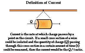
Current electricity refers to the continuous movement of electric charge through a conductor, usually a metal wire. This movement of electrons allows electrical energy to be transferred and converted into heat, light, motion, or magnetic effects. The rate of charge flow is measured in amperes, a foundational idea explained further in basic electricity.
When an electric heater warms up, a motor turns, or a light illuminates, it is because current electricity is flowing through a circuit and encountering resistance. This steady flow is the basis of all practical electrical systems and is described in more detail in explanations of current electricity.
Current electricity can be produced chemically, as in batteries, or mechanically, as in generators. Large-scale production methods are explained in resources on electricity generation, which show how mechanical motion is converted into electrical energy without changing the underlying type of electricity produced.
Direct Current and Alternating Current
Electricity can exist in two forms: direct current and alternating current. The difference lies in how electrons move through the circuit.
Direct current flows in one direction only. This stable and predictable flow makes DC ideal for electronics, batteries, and solar power systems. Even devices that plug into wall outlets typically convert incoming power to DC internally because electronic components require it. More detail is available in explanations of direct current.
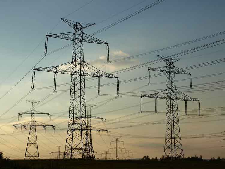
Alternating current reverses direction at regular intervals. This reversing motion allows voltage to be easily increased or decreased using transformers, which makes long-distance transmission far more efficient. For this reason, AC dominates electrical grids and household supply systems. The operating principles are outlined in discussions of alternating current, and the practical differences are explored further in the difference between AC and DC.
This ability to transform voltage levels is why AC is used for distribution, while DC is often used inside devices where stability and control matter more than transmission efficiency.
Types of Electricity Comparison Table
| Type of Electricity | Charge Behavior | Common Sources | Typical Uses |
|---|---|---|---|
| Static Electricity | Electric charge builds up on a surface and remains at rest | Friction, contact and separation, atmospheric charge | Lightning, photocopiers, laser printers |
| Direct Current (DC) | Electrons flow continuously in one direction | Batteries, solar panels, rectifiers | Electronics, battery-powered devices |
| Alternating Current (AC) | Electrons flow and reverse direction periodically | Generators, power grids | Wall outlets, motors, transformers |
Why These Types Matter in Real Systems
Understanding the differences between static electricity, direct current, and alternating current explains why electrical systems are designed the way they are. Power grids rely on AC for efficient transmission, electronics rely on DC for stable operation, and static electricity explains both natural phenomena and specialized technologies. In industrial and commercial environments, these principles extend to systems such as three-phase power, where alternating current is distributed across multiple conductors to deliver energy to large loads efficiently.
Safety Considerations
Regardless of type, electricity can be hazardous if not properly controlled. Both AC and DC can cause shock, burns, or equipment damage, which is why grounding, insulation, and protective devices are essential. An overview of these risks and protective measures is provided in electricity safety.
Related Concepts
To explore these ideas further, readers often move from this topic to foundational explanations of what is electricity, practical comparisons such as difference between AC and DC, and system-level discussions found in electric power systems.
Related Articles

