DC Current - Electricity Explained

By R.W. Hurst, Editor


DC current delivers unidirectional electron flow with constant polarity, powering circuits, batteries, and electronics; characterized by steady voltage, low ripple, and efficient distribution via rectifiers, converters, and regulated power supplies in electrical engineering.


What Is DC Current?

DC current is unidirectional electron flow with constant polarity, providing steady voltage for efficient power delivery

✅ Provides constant voltage for sensitive electronics and logic circuits

✅ Generated by batteries, fuel cells, solar PV; produced via rectification

✅ Enables precise control in motors, sensors, and industrial automation


DC current is essential to electrical energy, powering devices ranging from small electronic gadgets to electric vehicles. We can appreciate its significance in modern life by understanding its properties, applications, and relationship to other electrical concepts such as voltage, resistance, and Ohm's Law. Despite its limitations in power transmission over long distances, the use of DC current in solar energy systems and electric vehicles continues to demonstrate its vital role in an increasingly electrified world. For a practical primer, the direct current overview clarifies key concepts used in everyday systems today.


Direct current (DC) and alternating current (AC) are the two primary forms of current that power various electrical devices and systems. As the name suggests, direct current flows in a single, unidirectional direction, while alternating current oscillates in direction and magnitude. This article will explore the fundamental concepts of DC current, its applications, and its relationship to other aspects of electricity. For deeper contrasts, the difference between AC and DC guide expands on efficiency, safety, and conversion considerations for designers.

It is the flow of electric charge (electrons) in a consistent direction across a conductor, such as a wire. The consistent flow differentiates it from AC, where the direction of the flow periodically reverses. One of the most significant differences between DC and AC current is their power transmission method. DC systems transmit power at a constant voltage, while AC power alternates at a specific frequency. Complementing this, an accessible alternating current explainer details waveform behavior and frequency effects relevant to grid systems.

Electrical circuits using DC current play an essential role in many everyday devices and systems. Some common applications of DC current include batteries, solar panels, and electronic devices. Batteries are a prime example of a DC power source, as they generate a steady flow of electrons from one terminal to another. Solar panels, on the other hand, convert sunlight into DC electrical energy, which can then be stored in batteries or transformed into AC for use in homes or businesses. If you're new to the topic, this current electricity introduction connects sources like batteries and solar arrays to practical loads in simple terms.

In DC current circuits, voltage and resistance are essential factors influencing the flow of electric charge. Voltage refers to the electric potential difference between two points, whereas resistance represents the opposition to the flow of current. Ohm's Law, a fundamental principle in electrical engineering, states that the current flowing through a conductor between two points is directly proportional to the voltage across those points and inversely proportional to the resistance between them. In other words, the higher the voltage or, the lower the resistance, the greater the current. A concise current reference ties these relationships to measurement practices and typical units used in labs.

DC current also plays a critical role in electric vehicles, where it is converted from high-voltage batteries to the required voltage for the electric motor. This conversion from DC to AC is essential because electric motors typically function on AC power.

DC current presents both advantages and disadvantages. One of its main benefits is its simplicity, as it maintains a constant voltage and current flow, making it easier to work with in electronic devices. Additionally, its unidirectional flow allows for more efficient power storage in batteries. However, one significant drawback is that it could be better suited for long-distance power transmission, as it suffers from substantial power loss over long distances.

The story of electricity would be incomplete without mentioning the famous "Battle of the Currents" between Thomas Edison, a staunch advocate of DC systems, and George Westinghouse, who supported AC systems. Ultimately, AC power emerged as the winner for power distribution due to its ability to transmit power over long distances with minimal energy loss. For historical and conceptual grounding, an electricity definition frames how these terms evolved across scientific practice.


DC Current Calculator Explained

A DC current calculator is a tool that helps to determine the direct current flowing through an electrical circuit based on known values of voltage, resistance, and sometimes power. It is used to simplify and verify calculations related to DC circuits and ensure proper circuit design, maintenance, and troubleshooting. The calculator uses Ohm's Law and the power equation as the basis for its calculations.

Ohm's Law states that the current (I) flowing through a conductor between two points is directly proportional to the voltage (V) across those points and inversely proportional to the resistance (R) between them. The formula is:

I = V / R

In addition to Ohm's Law, the power equation can be used to determine the current in a circuit when the power (P) and voltage (V) are known:

P = IV

By rearranging this formula, we can find the current:

I = P / V

To use a calculator, you will typically input the known voltage, resistance, and/or power values, and the calculator will solve for the unknown variable (in this case, the current). For safe circuit operation, some calculators may provide additional information, such as power dissipation or required resistor wattage. If you need a refresher before using calculation tools, this basic electricity primer reviews units, symbols, and safety fundamentals that prevent common mistakes.

A calculator is especially useful for electrical engineers, technicians, and hobbyists working with DC circuits to verify their calculations or diagnose issues within the circuit. It can help ensure the proper functioning of electronic devices, efficient energy usage, and the safety of the electrical components within a system.

Related News

Dynamic Electricity Explained

Dynamic electricity is the continuous flow of electric charge—electric current—through a conductor, typically driven by a voltage source. Think of it like water flowing in a pipe, where electrons move uniformly to carry energy.


What is Dynamic Electricity?

Dynamic electricity refers to the continuous movement of electric charges, commonly known as electric current.

  • Describes the flow of electrons or electric charge through a conductor

  • Facilitates energy transfer, enabling devices and machines to operate

  • Used in powering household appliances, industrial processes, lighting, and electronics

It is the continuous flow of electric charges through a conductor, commonly referred to as electric current. Think of it like water flowing through a pipe: voltage acts as water pressure, current as the flow of water, and resistance as the size of the pipe. This motion of electrons is what powers devices, lights homes, and drives entire industries.

Unlike static electricity, which involves charges at rest, dynamic electricity is defined by the constant movement of charge carriers, making it the foundation of modern electrical systems. To understand how voltage, current, and resistance interact in circuits, see our detailed guide on Ohm’s Law.

It depends on the movement of charges through conductive materials. Learn more about the difference between conductors and electrical insulators.

Dynamic electricity is closely tied to the concept of electrical energy, which is produced when an energy source creates movement between charges. A negative charge is naturally drawn toward a positively charged region, and objects with opposite charges will attract one another. This interaction between positive and negative charges is the foundation of current flow. Every type of electrical system, from simple batteries to complex power grids, relies on this basic principle to generate and transfer usable energy.


How It Works (Voltage, Current, Ohm’s Law)

Dynamic electricity occurs when a voltage difference is applied across a conductor, such as copper or aluminum wire. This creates an energy imbalance that causes electrons to flow from one end to the other.

  • Electrons drift slowly, but the electrical effect travels nearly at the speed of light, allowing instant energy transfer.

  • The flow of current is governed by Ohm’s Law: V = IR, where voltage (V) equals current (I) times resistance (R).

  • Moving charges generate magnetic fields and produce heat, demonstrating the role of resistance in circuits and enabling the operation of motors, electromagnets, and heating devices.

  • Current is measured in amperes (A), typically using an ammeter or other measurement instruments.

Electric current is measured in amperes, a unit explained in our introduction to electrical current.

The safe handling of flowing charges requires proper electrical grounding techniques to prevent hazards.

Analogy: Imagine marbles in a tube. Push one marble in, and the entire line shifts almost instantly. Similarly, electron movement is slow, but the effect propagates quickly through the entire circuit.


AC vs DC Explained

Type of Current Description Common Uses Advantages
Direct Current (DC) Electrons flow in a single, steady direction Batteries, electronics, solar panels, EVs Stable output, essential for digital devices and storage systems
Alternating Current (AC) Electron flow reverses direction periodically Power grids, appliances, and industrial systems Efficient long-distance transmission, adaptable to transformers


  • Why AC? Its ability to change voltage levels makes it ideal for transmitting energy over long distances with minimal energy loss.
  • Why DC? Critical for low-voltage devices, renewable integration, and battery storage, where stable current is required.

For a deeper look at how alternating current functions in grids, see our overview of alternating current.

Direct current plays a vital role in storage and electronics. Explore its applications on our page on direct current.


Everyday Applications

Dynamic electricity drives nearly every aspect of modern life:

  • Homes: power lighting, appliances, heating, and electronics.

  • Industry: runs motors, automation systems, and manufacturing equipment.

  • Transportation: essential for electric vehicles, rail systems, and aviation technologies.

  • Renewable energy: harnessed by solar panels, wind turbines, and hydroelectric systems, which is then transmitted via power grids over long distances through reliable power transmission systems.

  • Energy storage: stored in batteries to support grid reliability and electric mobility.

  • Communication systems: support telecom networks, internet infrastructure, and data centers.

In renewable energy systems, dynamic electricity is produced and stored for later use. Learn how it relates to energy storage.

The flow of current must be managed carefully in fault conditions. For details, see our guide on fault current calculation.


Safety and Control

Because moving charges create heat, sparks, and electromagnetic fields, electrical circuits are designed with protective devices:

  • Circuit breakers and fuses prevent overheating and fire risks.

  • Insulation and grounding ensure safe handling of conductors.

  • Control systems regulate current flow for efficiency and reliability.

Circuit safety relies on protective systems. Explore our page on electrical protection for more details.


Static vs Dynamic Electricity

Understanding the difference is key:

  • Static

    • Charges accumulate on surfaces.

    • It can cause small shocks or sparks.

    • Temporary and uncontrolled.

  • Dynamic

    • Charges move continuously through conductors.

    • Power devices and grids.

    • Reliable and controllable.


Future Challenges and Developments

The demand for dynamic electricity is expanding as society transitions to net-zero energy systems. Key developments include:

  • Smart grids to balance supply and demand.

  • Advanced energy storage to integrate renewable sources.

  • Global electrification in emerging economies, driving higher usage worldwide.

It will continue to shape technology, transportation, and sustainability goals in the decades ahead.


Frequently Asked Questions


What is the difference between static and dynamic electricity?

Static involves charges at rest, while dynamic is defined by moving charges, producing electric current used to power systems.


Why is it important in daily life?

It powers homes, industries, transport, communication, and renewable energy systems, making it the foundation of modern civilization.


How is it measured?

It is measured in amperes (A), using tools like ammeters to detect the flow of current in a circuit.


Related Articles


View more

Resistances in Parallel

Resistances in parallel share voltage, add conductances, and reduce equivalent resistance; apply Ohm's law, current division, and circuit analysis to compute total R, branch currents, and power distribution in multi-branch networks.


What Are Resistances in Parallel?

Parallel resistors share voltage; total resistance decreases by summing conductances (1/R).

✅ Equivalent 1/Rt = sum(1/Ri); lower than smallest branch

✅ Same voltage across branches; currents split by conductance

✅ Use Ohm's law and current division to size components, power


Resistances in parallel is a common term used in industrial, commercial, and institutional power systems. Therefore, a good understanding of working with resistors in parallel and calculating their various parameters is crucial for maintaining safe and efficient operations. For foundational context, see this overview of electrical resistance for key definitions applied throughout.

It means that when resistors are connected in parallel, they share the same voltage across them. Hence, this means that the resistances are in parallel. This is because the total resistance of the resistors in parallel is less than that of any individual resistor, making it a useful configuration for reducing resistance and increasing current in a circuit. A clear grasp of electrical resistance helps explain why parallel branches draw more current.

Adding more resistors in parallel reduces the circuit's total resistance, increasing the current. However, adding too many resistors in parallel can overload the circuit and cause it to fail. Engineers often verify safe loading using the resistance formula to predict current increases.


Understanding Resistances in Parallel

They refer to the configuration in which two or more resistors are connected side by side across the same voltage points in an electrical circuit. In this arrangement, the voltage across each resistor is the same, while the current is divided among the resistors according to their resistance values. This configuration is commonly used in circuit analysis to simplify complex circuits and determine the equivalent parallel resistance.

When simplifying networks, computing the equivalent resistance streamlines analysis and component selection.


Calculating the Equivalent Resistance

To calculate the equivalent resistance of resistances in parallel, the reciprocal of the equivalent resistance (1/Req) is equal to the sum of the reciprocals of the individual resistances (1/R1 + 1/R2 + ... + 1/Rn). This formula is crucial in resistance calculation and helps engineers design efficient power systems that meet the desired voltage drop and current distribution requirements. A comparable reciprocal relationship appears when evaluating capacitance in series under similar analysis methods.

To calculate the total resistance of resistors in parallel, the reciprocal of each resistor is added together, and then the result is inverted to give the total resistance. This can be represented mathematically as:

1/Rt = 1/R1 + 1/R2 + 1/R3 + ...

where Rt is the total resistance and R1, R2, R3, etc. are the individual resistors.


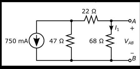
Five resistors R(1) through R(5), connected in parallel, produce a net resistance R.


In a circuit with resistors in parallel, the current is divided among the resistors according to their individual resistance values. This is known as the current division, and it can be calculated using Ohm's law and the circuit's total resistance. The formula for calculating the current through each resistor in parallel is:

I1 = (V/R1) * (R2/(R2 + R3)) I2 = (V/R2) * (R1/(R1 + R3)) I3 = (V/R3) * (R1/(R1 + R2))

where I1, I2, and I3 are the currents through each resistor, V is the voltage across the circuit, and R1, R2, and R3 are the individual resistors.

Simplifying a circuit with resistors in parallel involves finding the equivalent resistance of the circuit. This is the resistance value that would produce the same current as the original parallel circuit, and it can be calculated using the reciprocal formula:

1/Req = 1/R1 + 1/R2 + 1/R3 + ...

where Req is the equivalent resistance.


Impact on Total Resistance

In a parallel configuration, adding more resistors decreases the total resistance. The reason is that the current has multiple paths to flow through, reducing the overall opposition to current flow. This characteristic is particularly useful in designing power supply systems, where lower resistance is desired to minimize energy losses and improve system efficiency. By contrast, capacitance in parallel increases as components are added, offering a helpful design analogy.


Practical Applications

They are employed in various real-life circuits and power systems. For instance, they are commonly found in circuit simulations, power distribution systems, and load balancing applications. In industrial settings, a parallel resistor calculator is often used to measure multiple current paths for fault protection and redundancy. In commercial and institutional power systems, parallel configurations are employed to manage load distribution and ensure system reliability.


Differences between Parallel and Series Connections

In a series circuit, resistors are connected end-to-end, and the current flows consecutively from the source of each resistor. The total resistance in a series circuit equals the sum of individual resistances, and the voltage drop across each single resistor is different. In contrast, they share the same voltage, and the total resistance decreases as more resistors are added. Identifying these connections in a circuit diagram is crucial for proper circuit analysis and design. For direct comparison of methods, review resistance in series to see how sums differ from reciprocals.


Combining Resistances in Parallel and Series

They can be combined with resistances in series within the same circuit. In such cases, equivalent resistances for both parallel and series sections are calculated separately. Then, the total resistance is determined by adding the equivalent resistances of the series and parallel sections. This approach helps engineers analyze complex circuits and design efficient power systems.

They are crucial to industrial, commercial, and institutional power systems. Understanding how to calculate the total resistance, current distribution, and power dissipation of resistors in parallel is essential for maintaining safe and efficient operations. In addition, engineers can optimize their designs for optimal performance by using circuit simulation software and other tools.


Related Articles

View more

Green Electricity

Green electricity integrates renewable energy sources such as solar PV, wind turbines, and hydropower into smart grids, improving power quality, decarbonization, efficiency, and reliability for industrial loads and utility-scale networks.


What is green electricity?

Green electricity is renewable-source power via smart grids to cut emissions and enhance system efficiency.

✅ Integrates PV, wind, hydro with power electronics and converters

✅ Enhances grid stability via inverters, FACTS, and smart protection

✅ Reduces CO2, improves efficiency, supports microgrids and storage


Green electricity is a term describing what is thought to be environmentally friendly sources of electricity. Typically, this refers to renewable and non-polluting energy power sources. For a broader perspective on how different technologies contribute, see this overview of sources of electricity across modern grids.

Green electricity includes natural energetic processes which can be harnessed with little pollution. Anaerobic digestion, geothermal power, wind power, small-scale hydropower, solar power, biomass power, tidal power and wave power fall under such a category. Some versions may also include power derived from the incineration of waste. Comparisons with other clean options are summarized in this guide to alternative electricity solutions used worldwide.


Energies Wind Electricity 
The winds that blow across the UK can be harnessed by turbines to provide Green electricity. Wind turbines sited in suitable locations already provide a small, but growing percentage of the UK's electricity, and are used successfully all around the world. In fact wind power is the world's fastest growing energy source! Wind turbine technology has greatly improved over the last ten years, making wind turbines quieter and more efficient so that electricity generated from the wind is now often competitive with traditional coal-fired and nuclear power stations. Wind turbines are also beginning to be built at sea — in the future much of our electricity could come from these offshore windfarms. Understanding how turbines integrate into national systems is covered in this primer on electricity generation methods and planning.


Solar Electricity
Many people believe that we don't get much solar Green electricity here in the UK. In fact solar power is already being used to provide essential power for many types of equipment being used in both remote and urban areas across the country. A solar photovoltaic (PV) module works by converting sunlight directly into electricity (even on cloudy days) using semiconductor technology. The vast majority of solar modules available today use "waste" silicon from the computer chip industry as the semiconductor material. They can be integrated into buildings and even made into roof tiles virtually indistinguishable from normal tiles. 
Solar Electricity can also be used to heat water directly using specially designed collectors. Even in winter a useful amount of hot water can be produced from roof top collectors. A third way to use solar energy is simply to design buildings to make maximum use of the sun. Using this so-called 'passive solar' approach, much of the energy that we currently use for heating, lighting and air conditioning can be saved. Homeowners can explore practical steps to generate electricity with rooftop PV and storage.


Hydro Electricity
Water turbines have been used to provide Green electricity for over 100 years and presently provide over 1% of the UK's electricity. Although most of the possible sites for large hydropower stations in the UK have already been developed, there is a large potential for smaller schemes. These can either use a small dam or work as a 'run of the river' system which has a minimal impact on the local environment. Design considerations for small schemes are outlined in this resource on water electricity systems for communities.


Wave Electricity
Many different devices have been designed over the years to try and capture some of this huge energy resource — the latest one has recently started generating Green electricity on the isle of Islay, off the West Coast of Scotland. In this machine waves hitting the shore are channelled into a large tube to power a specially designed turbine. With the proper support, wave power could provide a significant proportion of the UK's electricity needs in the future.


Tidal Electricity
Tidal power has been used in Britain for over a thousand years — at the time of the Doomsday book over 5,000 tide powered mills were recorded. Unlike other Green electricity renewable energy sources, which depend on the weather, tidal power is as predictable as the tides themselves. One way to capture tidal energy is to build a barrage across an estuary, storing water behind it as the tide rises and then releasing the stored water through turbines at low tide. Several sites around the UK could be suitable for this type of tidal system, the largest being the Severn Estuary. Another way is to use 'marine current turbines', which work like underwater wind turbines, harnessing tidal currents instead of the winds.


Geothermal Electricity
Geothermal energy comes from hot rocks deep underground. In some parts of the world steam comes to the surface and can be used to run steam turbines to produce Green electricity directly. In other places water can be pumped down and heated by the rocks to make steam. Geothermal energy can also be used to provide hot water and heating for buildings. Case studies of enhanced systems are available in this overview of geothermal electricity projects worldwide.


Biomass Electricity
Either agricultural wastes or specially grown plants can be used as a fuel to run small Green electricity power stations. As plants grow they absorb carbon dioxide (the main gas responsible for climate change) which is then released when the plants are burnt. So using biomass does not add any extra carbon dioxide into the atmosphere. Specially grown 'energy crops' provide not only an environmentally sound source of electricity, but also an important new opportunity for farmers. Analyses of supply chains and grid impacts appear in this review of electricity production from biomass and other renewables.


Landfill gas Converted to Electricity
As rubbish decomposes in the landfill sites where our household waste is dumped, it gives off methane gas. This gas can be captured and burnt in a gas turbine to produce an attractive Green electricity tariff. Burning the gas does give off carbon dioxide but since methane, which is emitted from the landfill site, is in fact a much more powerful greenhouse gas it is better to burn it than to allow the methane to escape into the atmosphere. There are already many landfill gas systems operating in the UK.


Waste Incineration Electricity
The UK generates an enormous amount of waste, and space at landfill sites is quickly running out. The best solution would be to recycle as much of the waste as possible, but instead incinerators are being constructed to burn the waste. In some cases the energy is being used to generate green electricity. However many environmentalists are still concerned about the emission of harmful dioxins and also about the loss of a valuable resources that could have been recycled. You can read about Greenpeace's views on incineration.


Related Articles

View more

Impedance Definition

Impedance Definition Explained

Understanding the concept of impedance (Z) is crucial for anyone working with or studying electrical circuits, particularly those involving alternating current (AC). To grasp the intricacies of impedance, it is essential to explore its definition and the various factors that come into play.

The term "impedance" is defined as the opposition that an electrical circuit presents to the flow of an alternating current (AC) or voltage. It is a complex quantity that includes both resistance and reactance components, making it vital in AC circuit analysis. Electrical impedance is essential in determining how electrical energy flows through a circuit, and it is influenced by various factors such as resistance, reactance, and frequency.

Resistance and reactance are two key elements that make up impedance. While resistance is the opposition to the flow of direct current (DC), reactance opposes the flow of AC. Reactance itself is composed of two parts: capacitive and inductive impedance. Capacitive impedance is due to the presence of capacitors in the circuit, while inductive impedance results from the presence of inductors.

Impedance is crucial in AC circuit analysis because it enables engineers and technicians to calculate how AC voltage and current behave within a circuit. This knowledge is necessary when designing and troubleshooting electrical systems. Furthermore, understanding impedance helps identify the optimal conditions for efficient energy transfer, as demonstrated by impedance matching.


Impedance matching refers to adjusting the Z of a source and load to match, maximizing the power transfer between the two. This is essential in various applications such as radio frequency (RF) communications, audio systems, and power transmission.

Calculating the total impedance (Z_total) in a circuit involves considering both the resistive and reactive components. For a series circuit, the total impedance is calculated using Ohm's law as follows:


Z_total = √ (R_total^2 + (X_L - X_C)^2)


Here, Z_total represents total impedance, R_total is the total resistance, X_L is the inductive reactance, and X_C is the capacitive reactance. In parallel circuits, the total impedance is computed by determining the reciprocal of the sum of the reciprocals of individual impedances.

Capacitive and inductive impedance play significant roles in AC circuits. As the frequency of the AC signal changes, the impedance of capacitors and inductors in the circuit also changes. As a result, capacitive impedance decreases with increasing frequency while inductive impedance increases. This characteristic can be utilized to design filters that selectively allow specific frequency ranges to pass through, shaping the output signal as desired.

Impedance spectroscopy is a technique that examines the Z of a material or device over a range of frequencies. This process provides valuable information on the electrical properties and behaviour of the material, enabling researchers and engineers to gain insight into various phenomena such as conductivity, dielectric properties, and electrochemical reactions. This knowledge can be applied to optimize the design and performance of various materials and devices.

Impedance definition and its various aspects, including electrical impedance, complex impedance, impedance matching, and impedance spectroscopy, are essential to understanding AC circuit analysis and the behaviour of electrical circuits in different applications. By examining the interplay of resistance and reactance and the influence of electric and magnetic fields, engineers can design and optimize circuits to ensure maximum efficiency and functionality.

View more

Resistance in Series Explained

Resistance in series refers to the arrangement of individual resistors in a circuit, where the current flows through each resistor end to end. In this configuration, the total resistance (R) of the circuit is equal to the sum of the individual resistances, also known as the equivalent R.


What is Resistance in Series?

Resistance in series refers to a circuit configuration where resistors are arranged in a single path:

✅ Total resistance is the sum of all resistors in the circuit

✅ The same current flows through each resistor

✅ Voltage divides across each resistor based on its value

To calculate the total R in a series circuit, the individual resistances of each resistor are added together. The formula to calculate the equivalent resistance in a series connection is Rtotal = R1 + R2 + R3 + ..., where R1, R2, R3, and so on, represent the individual resistances of each resistor in the circuit.

Ohm's law also applies to series circuits, where the current through each resistor is the same, but the voltage across each resistor is proportional to its R. The total voltage across the series combination of resistors equals the sum of the voltage drops across each resistor.

It is essential to note that the total resistance in a series circuit is always greater than the resistance of any individual resistor in the circuit, due to the cumulative effect of each resistor's resistance.

On the other hand, resistors connected in parallel result in a parallel circuit. The equivalent R of a parallel circuit is calculated differently from a series connection. Instead of adding the individual resistances, the reciprocal of each R is added, and the resulting value is inverted to obtain the equivalent resistance.


R in Series - Parallel

When you place R-I-S, their ohmic values add up arithmetically to reach the total (or net) R.

We can connect a series of resistors (equal to the sum of the individual resistances of a parallel circuit), all having identical ohmic values, in parallel sets of series networks or series sets of parallel networks. When we do either of these things, we create a series-parallel network that can significantly increase the total power-handling capacity of the network compared to the power-handling capacity of a single parallel resistor.


Fig. 4-14. Three resistors in series. 

Sometimes, the total single equivalent R of the combination circuit in a series-parallel network equals the value of any one of the resistors. This always happens if the parallel branches or parallel combinations of the connection components are all identical and are arranged in a network called an n-by-n (or n x n) matrix. That means when n is a whole number, we have n series sets of n resistors connected in parallel, or else we have n parallel sets of n resistors connected in series in the circuit. These two arrangements yield the same practical result for electrical circuits.

A combination of series parallel combinations array of n by n resistors, all having identical ohmic values and identical power ratings, will have n2 times the power-handling capability of any resistor by itself. For example, a 3 x 3 series-parallel matrix of 2 W resistors can handle up to 32 x 2 = 9 x 2 = 18 W. If we have a 10 x 10 array of 1/2 W resistors, then it can dissipate up to 102 x 1/2 = 50 W. We multiply the power-handling capacity of each individual resistor by the total number of resistors in the matrix.

The above-described scheme works if, but only if, all of the resistors have identical ohmic values according to ohms law and identical power-dissipation ratings in terms of total voltage drops when the sum of the voltage drops across each resistor. If the resistors have values that differ even a little bit from one another, one of the components will likely draw more current than it can withstand, so that it will burn out, no matter the voltage source. Then the current distribution in the network will change further, increasing the likelihood that a second resistor will fail, and maybe more.

If you need a resistor that can handle 50 W, and a certain series-parallel connection of the network will handle 75 W, that's fine. But you should not "push your luck" and expect to get away with using a network that will handle only 48 W in the same application. You should allow some extra tolerance, say 10 per cent over the minimum rating. If you expect the network to dissipate 50W, you should build it to handle 55W or a bit more. You don't have to use "overkill," however. You'll waste resources if you cobble together a network that can handle 500W when you only expect it to cope with 50W—unless that's the only convenient combination you can make with available resistors.


Related Articles


View more

Types of Electricity - Static and Current

Types of electricity include static electricity and current electricity, which flows as direct current (DC) or alternating current (AC). Electricity can be generated from various sources, including solar, wind, and hydro, but all supply either static or current electricity.


What are the Types of Electricity?

There are two types of electricity: Static Electricity and Current Electricity.

Static electricity results from the buildup of electric charges.

✅ Current electricity includes alternating (AC) and direct (DC) flow.

Static Electricity is made by rubbing together two or more objects, creating friction, while Current electricity is the flow of electric charge across an electrical field.


Static Electricity

Static electricity is when electrical charges build up on the surface of a material. It is usually caused by rubbing materials together. The result of a build-up of static electricity is that objects may be attracted to each other or may even cause a spark to jump from one to the other. For Example, rub a balloon on a wool and hold it up to the wall.

Before rubbing, like all materials, the balloons and the wool sweater have a neutral charge. This is because they each have an equal number of positively charged subatomic particles (protons) and negatively charged subatomic particles (electrons). When you rub the balloon with the wool sweater, electrons are transferred from the wool to the rubber because of differences in the attraction of the two materials for electrons. The balloon becomes negatively charged because it gains electrons from the wool, and the wool becomes positively charged because it loses electrons.


Current Electricity

Current is the rate of flow of electrons. The movement of electrons produces it, and it is measured in amperes. Unlike static electricity, current electricity must flow through a conductor, usually copper wire. Electricity is similar to the flow of water in a river. The river flows from one spot to another, and the speed of the current determines the speed at which it moves. With electricity, current is a measure of the amount of energy transferred over a period of time. That energy is referred to as an electron flow. One of the results of the current is the heating of the conductor. When an electric stove heats up, it's because of the flow of current.

There are various sources of current electricity, including the chemical reactions that occur in a battery. The most common source is the generator. A simple generator produces electricity when a coil of copper turns inside a magnetic field. In a power plant, electromagnets spinning inside many coils of copper wire generate vast quantities of electricity.

There are two main kinds of electric current. Direct (DC) and Alternating (AC). It's easy to remember. Direct current is similar to the energy you obtain from a battery. Alternating current is like the plugs in the wall. The big difference between the two is that DC is a flow of energy, while AC can turn on and off. AC reverses the direction of the electrons.


Related Articles


View more

Sign Up for Electricity Forum’s Newsletter

Stay informed with our FREE Newsletter — get the latest news, breakthrough technologies, and expert insights, delivered straight to your inbox.

Electricity Today T&D Magazine Subscribe for FREE

Stay informed with the latest T&D policies and technologies.
  • Timely insights from industry experts
  • Practical solutions T&D engineers
  • Free access to every issue

Live Online & In-person Group Training

Advantages To Instructor-Led Training – Instructor-Led Course, Customized Training, Multiple Locations, Economical, CEU Credits, Course Discounts.

Request For Quotation

Whether you would prefer Live Online or In-Person instruction, our electrical training courses can be tailored to meet your company's specific requirements and delivered to your employees in one location or at various locations.