Electrical Resistance Explained

Electrical Resistance

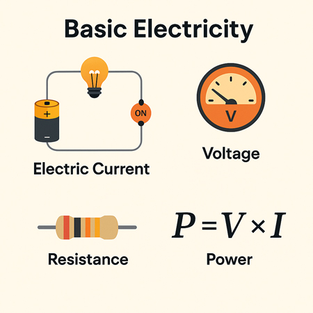
Electrical resistance is the opposition to the flow of electric current in a material. It is measured in ohms (Ω) and depends on the conductor’s length, thickness, material, and temperature.


What is Electrical Resistance?

Electrical resistance is a fundamental concept in engineering that defines how much a material opposes the flow of electric current. Measured in ohms (Ω), resistance (Ω) plays a crucial role in circuit design, power distribution, and electronic applications.

✅ Measured in ohms (Ω) and calculated using Ohm’s Law

✅ Influenced by material, length, area, and temperature

✅ Key factor in circuit safety, design, and energy loss


Think of electricity moving like water through a pipe. If the pipe is narrow or obstructed, less water flows through it. Similarly, in a wire or conductor, certain materials make it harder for electrons to move freely. This obstruction results in energy loss, often seen as heat.

The ease or difficulty of electric charge movement depends on the conductivity of a material. Metals like copper allow current to flow easily, while rubber or glass inhibit it entirely. This behavior plays a key role in how systems are designed and protected. Discover how resistors are used in circuits to manage voltage and protect components by providing controlled resistance.


Electrical Resistance – Example Values by Material/Component

Material/Component Approx. Resistance Notes
Copper wire (1 meter, 1mm²) ~0.017 ohms Very low resistance, ideal for conductors
Aluminum wire (1m, 1mm²) ~0.028 ohms Higher resistance than copper
Iron wire (1m, 1mm²) ~0.10 ohms Often used in heating elements
Nichrome wire (1m, 1mm²) ~1.10 ohms High-resistance alloy used in toasters and heaters
Human body (dry skin) 1,000–100,000 ohms Varies greatly with moisture and contact
Incandescent light bulb ~240 ohms (cold) Resistance increases when hot
Resistor (carbon film) Fixed (e.g., 220 ohms) Used to control current in circuits
Air (dry) ~1 trillion ohms (insulator) Excellent natural insulator unless ionized
Superconductor 0 ohms Only at extremely low temperatures (near absolute zero)


Electrical Resistance Definition

Several factors affecting electrical resistance include the type of material, temperature, and the dimensions of the conductor. When an electric charge moves through a material, its ease of flow depends on the material’s conductivity. A high-conductivity material allows charges to move more freely, resulting in lower resistance. The resistance of a conductor increases with its length and decreases with its cross-sectional area. Therefore, the resistance of a wire is directly related to both its physical properties and the material from which it is made. The resistance of a conductor depends heavily on its length and cross-sectional area, as outlined in our resistance formula breakdown.

This opposing property is quantified using Ohm’s Law:

R = V / I

Where:

  • R is the resistive value in ohms

  • V is voltage (volts)

  • I is current (amperes)

Another useful expression involves material properties:

R = ρ × (L / A)

Where:

  • ρ is resistivity (material-specific)

  • L is length

  • A is cross-sectional area

These formulas show that the longer or thinner the conductor, the harder it is for current to move through it.


Unit of Electrical Resistance – The Ohm (Ω)

The ohm is the SI unit of resistance, named after German physicist Georg Ohm. One ohm is defined as the resistance between two points of a conductor when a potential difference of one volt causes a current of one ampere to flow.

Common multiples:

  • kΩ (kilo-ohm) = 1,000 ohms

  • MΩ (mega-ohm) = 1,000,000 ohms

Resistance can be measured using a multimeter, and is especially important in designing and troubleshooting power  and electronic circuits. To understand how voltage and resistance interact in a circuit, see our guide on Ohm’s Law.


Ohm’s Law and Circuit Function

Ohm’s Law helps us understand how voltage, current, and resistance relate. For example:

  • Increase the resistive load, and current drops.

  • Increase voltage with fixed resistance, and current rises.

These principles help control energy flow, prevent overloads, and design efficient systems.


Measuring and Expressing Opposition

The ohm (Ω) is the standard unit used to quantify this phenomenon. One ohm means that a current of one ampere flows when one volt is applied. Components with fixed values, like resistors, are labelled accordingly—e.g., 100 Ω, 1 kΩ, or 1 MΩ.

To measure the current-limiting capacity of a material, a digital multimeter is used. It applies a small voltage and calculates the resulting current flow to determine the opposition level. If you're working with different wire types, explore the unit of electrical resistance for conversion insights and resistance ranges.


Real-World Examples of Resistance

  • Heating Elements: Toasters, ovens, and electric heaters utilize high-resistance materials, such as nichrome wire.

  • Power Transmission: Long-distance wires are designed with low resistance to reduce energy loss as heat.

  • Electronic Components: Resistors regulate current in circuits, protecting components from overload.

For real-world scenarios involving current flow, our article on voltage drop explains how resistance affects electrical efficiency over distance.


Factors Affecting Electrical Resistance

  • The resistance of a conductor depends on:

    • Material – copper vs. aluminum vs. nichrome

    • Length – longer wires restrict current more

    • Thickness – wider wires allow easier flow

    • Temperature – many materials resist current more when heated

    Thus, the resistance of a wire can vary dramatically depending on where and how it’s used. Materials with high conductivity (like silver or copper) allow electrons to move with minimal restriction, whereas poor conductors like rubber greatly hinder charge movement.


Superconductors – Zero Resistance?

In some materials, when cooled to extremely low temperatures, resistance drops to zero. These superconductors enable electricity to flow without energy loss, but their use is limited to specialized fields, such as MRI machines or experimental power lines, due to cost and cooling requirements.


Frequently Asked Questions


What causes electrical resistance?

It results from collisions between electrons and atoms in a conductor, which convert energy into heat.


What is the formula for calculating it?

 R = V/I or R = ρ × (L / A)


How is it measured?

With a multimeter in ohms (Ω), using a small test voltage and measuring current. Learn how instruments like a digital multimeter are used to measure opposition to current flow in electrical systems.


Why is this concept important?

It controls current flow, prevents damage, and enables functions like heating or dimming.


Can resistance ever be zero?

Yes—in superconductors under specific extreme conditions.

Electrical resistance is a foundational concept in understanding how electricity behaves in materials and systems. From household wiring to high-voltage power lines and sensitive electronics, it plays a crucial role in determining safety, efficiency, and performance. For a broader view on electric flow and material response, read about electrical conductivity and current electricity.


Related Articles


Related News

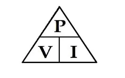
Watt’s Law - Power Triangle

Watt’s Law defines the relationship between power (watts), voltage (volts), and current (amps): Power = Voltage × Current. It’s used in electrical calculations to determine energy usage, system efficiency, and safe equipment ratings in both residential and industrial systems.


What is: Watt’s Law?

Watt’s Law is a fundamental principle in electrical engineering:

✅ Calculates electrical power as the product of voltage and current

✅ Helps design efficient and safe electrical systems

✅ Used in both residential and industrial applications

Watt’s Law is a fundamental principle in electrical engineering that defines the relationship between power, voltage, and current in an electrical circuit. James Watt invented the law. It states that the power (measured in watts) of an electrical device is equal to the product of the voltage (measured in volts) and the current (measured in amperes) flowing through it. In other words, the watt's law formula is expressed as: Power = Voltage × Current. This simple equation is essential for understanding how electrical components consume and distribute energy in a circuit. 

For example, consider a light bulb connected to an electrical circuit. The electrical potential (voltage) pushes the electric charge through the filament of the bulb, creating a flow of electrons (current). As the electrons flow, they generate heat and light, representing the bulb’s power in a circuit. By knowing the voltage and current, you can easily calculate the power output of the bulb. The wattage of the bulb indicates the energy consumed per second.

Practical applications of this formula are vast. This equation is especially useful in designing safe and efficient electrical systems. For instance, designing the wiring for both small devices and large power systems requires a thorough understanding of the relationship between voltage, current, and power. The formula helps ensure that systems are capable of delivering the required energy without causing failures or inefficiencies.

Ohm’s Law and this principle are often used together in electrical engineering. While power focuses on the relationship between voltage and current, Ohm’s Law deals with the relationship between voltage, current, and resistance (measured in ohms). Ohm’s Law states that voltage equals current multiplied by resistance (Voltage = Current × Resistance). By combining Ohm’s Law and this power equation, you can analyze an electrical system more comprehensively. For example, if you know the voltage and resistance in a circuit, you can calculate the current and then determine the power in the circuit. To fully understand Watt's Law, it helps to explore how voltage and current electricity interact in a typical electrical circuit.


Georg Simon Ohm – German physicist and mathematician (1787–1854), known for Ohm's Law, relating voltage, current, and resistance.


What is Watt's Law and how is it used in electrical circuits?

Watt’s Law is a fundamental principle in electrical engineering that defines the relationship between power, voltage, and current in an electrical circuit. The formula is expressed as:

Power (Watts) = Voltage (Volts) × Current (Amperes)

In simpler terms, Watt’s Law states that the electrical power consumed by a device (measured in watts) is the product of the electrical potential difference (voltage) and the current flowing through the circuit. Accurate calculations using Watt’s Law often require a voltage-drop calculator to account for line losses in long-distance wiring. Comparing voltage drop and voltage sag conditions illustrates how slight changes in voltage can have a substantial impact on power output.


James Watt – Scottish inventor and mechanical engineer (1736–1819), whose improvements to the steam engine led to the naming of the watt (unit of power).


How is it used? Watt’s Law is widely used to determine the amount of power an electrical device or system consumes. This is especially important for designing electrical circuits, optimizing power distribution, and ensuring the efficiency of devices. Here are a few examples of how it’s applied:

  • Electrical Circuit Design: Engineers use it to calculate the power consumption of devices and ensure that circuits can handle the expected electrical load. This helps prevent overloads and ensures that the wiring is safe.

  • Power Output Calculations: Using this formula, you can calculate the power output of a generator, appliance, or device, enabling you to match the right components to your system's requirements.

  • Energy Efficiency: Understanding power consumption in appliances and devices helps consumers make informed choices, such as selecting energy-efficient options. Devices like wattmeters and watthour meters measure power and energy usage based directly on the principles of Watt’s Law. For a deeper look at how devices like ammeters help measure current, see how their readings plug directly into Watt’s Law calculations.


How is Watt's Law different from Ohm's Law?

Watt’s Law and Ohm’s Law are both fundamental principles in electrical engineering, but they deal with different aspects of electrical systems:

  • Watt’s Law defines the relationship between power, voltage, and current. It focuses on the amount of energy used by a device in a given circuit. The formula is:

           Power = Voltage × Current

  • Ohm’s Law defines the relationship between voltage, current, and resistance in a circuit. Ohm’s Law explains how the current is affected by the voltage and the resistance present in the circuit. The formula for Ohm’s Law is:

            Voltage = Current × Resistance


Key Differences:

  • Focus: It focuses on power, while Ohm’s Law focuses on the flow of electricity in a circuit, particularly how resistance affects current.

  • Watt’s Law is used to determine the amount of power a device is consuming. Ohm’s Law, on the other hand, is used to calculate current, voltage, or resistance in a circuit depending on the other known variables.

  • Applications: It is applied when designing systems that require power management, such as calculating the power output or efficiency of devices. Ohm’s Law is used more in analyzing how current behaves in a circuit when different resistive elements are present.

By combining both laws, electrical engineers can gain a comprehensive understanding of how electrical systems function, ensuring that devices operate efficiently and safely. When used with Ohm’s Law, Watt's Law enables engineers to analyze both energy consumption and electrical resistance.

One key area of application is in energy consumption. By understanding the voltage and current values for a specific device, engineers can monitor the amount of energy the device consumes. This is especially important for managing energy usage in homes, businesses, and power systems. By applying the formula, you can identify inefficient devices and make more informed decisions about energy efficiency.

In renewable energy systems, such as solar panels and wind turbines, this principle plays a critical role in optimizing energy output. Engineers use the formula to calculate how much electrical energy is being generated and distributed. This is crucial for ensuring that power systems operate efficiently and minimize excess energy loss.

Another practical application of this formula is in the automotive industry. It is used to design vehicle charging systems and battery technologies. For example, electric vehicle (EV) charging stations depend on understanding voltage, current, and power to ensure efficient charging times. Engineers use the equation to calculate the charging capacity required for EV batteries, helping to create optimal charging solutions.

In large facilities like data centers, this Watt’s Law formula is used to ensure power distribution is efficient. By applying the relationship between power, voltage, and current, engineers can effectively manage power systems, thereby reducing energy consumption and operational costs. Proper energy management in data centers is crucial, as high power usage can result in significant energy costs.

This power formula is indispensable for electrical engineers and technicians. The applications of Watt’s Law extend across various industries and are utilized in everything from designing power system wiring to developing renewable energy technologies. By combining Ohm’s Law and this principle, electrical engineers can optimize the performance of electrical components, ensuring energy efficiency and system reliability. Understanding the role of a resistor in a circuit can reveal how power is dissipated as heat, a key concept derived from Watt’s Law.

Finally, visual tools like the Watt's Law triangle are often used to simplify the application of this principle, helping both professionals and students understand how to apply the formula. As technology advances and energy demands grow, this formula remains a key element in electrical engineering, guiding the development of more efficient systems for the future.


Related Articles


View more

Biot Savart Law Explained

The Biot Savart Law describes how electric current generates magnetic fields, showing the relationship between current, distance, and field intensity. It is a key principle in physics, electromagnetism, and electrical engineering used to calculate magnetic effects in circuits.


What is Biot Savart Law?

The Biot Savart Law is a fundamental principle in electromagnetism that quantifies the magnetic field generated by an electric current.

✅ Relates magnetic field strength to current magnitude and distance.

✅ Provides a mathematical basis for calculating magnetic fields in circuits.

✅ Essential for understanding electromagnetism, physics, and engineering design.


Biot Savart Law and the study of electromagnetism have always been a fascinating field of science that deals with the interaction between electric and magnetic fields. One of the cornerstones in this domain is this law, named after the French scientists Jean-Baptiste Biot and Félix Savart. This law plays a vital role in understanding the behaviour of magnetic fields produced by electrical currents. The relationship between electricity and magnetism is at the heart of the Biot Savart Law, showing how moving charges generate magnetic effects.

Delving deeper into this fascinating concept, Biot Savart Law describes the magnetic field generated by a tiny current flowing through a conductor. The law states that the magnetic field at a point is directly proportional to the current and inversely proportional to the square of the distance between the point and the current-carrying conductor. Furthermore, the magnetic field's direction is perpendicular to the plane formed by the unit vector and the straight wire carrying the current. When studying current flow, it helps to compare this law with Ampere’s Law, which is often applied to symmetrical conductors and steady-state conditions.


Biot Savart Law Explained

It is a fundamental principle in electromagnetism that describes the magnetic field produced by a steady electric current. It is named after French physicists Jean-Baptiste Biot and Félix Savart, who formulated the law in 1820. It provides a means to calculate the magnetic field at any point in space due to a specific current distribution.

In mathematical terms, the Biot Savart Law can be expressed as:

dB = (μ₀ / 4π) * (Idl × r̂) / r²

Here,

  • dB represents the tiny magnetic field vector produced by an infinitesimal current element (Idl),

  • μ₀ is the permeability of free space (a constant with a value of 4π × 10^(-7) Tm/A),

  • I is the current flowing through the current element,

  • dl is the infinitesimal length vector of the current element,

  • r is the distance between the current element and the point in space where the magnetic field is being calculated,

  • r̂ is the unit vector pointing from the current element to the point of interest.

The Biot Savart Law states that the magnetic field produced by a small segment of a current-carrying conductor is proportional to the current, inversely proportional to the square of the distance from the point of interest, and depends on the angle between the current segment and the line connecting the segment to the point of interest.

To find the total magnetic field at a point in space due to an entire current distribution, you need to integrate the magnetic field contributions from each infinitesimal current element over the entire current-carrying conductor:

B = ∫dB

The Biot Savart Law is particularly useful for calculating the magnetic field in cases with complex current configurations or where symmetry is not apparent. In addition, it is often applied in situations where Ampere's Law would be difficult or impossible to use. Common applications include calculating magnetic fields due to straight wires, loops, and solenoids. A foundation in basic electricity concepts makes it easier to understand how current elements combine to produce magnetic fields.


Maxwell's Equations

One might wonder about the relationship between the Biot Savart Law and Maxwell's Equations, a set of fundamental equations that govern the behaviour of electric and magnetic fields. It can be derived from Maxwell's Equations, specifically Ampere's Law, which establishes a connection between an electric current and the magnetic field it generates.

While the Biot Savart Law and Ampere's Law address magnetic fields, their focus and applicability differ. For example, the Biot Savart Law is more useful for calculating magnetic fields due to current loops or irregular current-carrying conductors. In contrast, Ampere's Law best suits symmetrical geometries and steady-state currents.

The practical applications of the Biot Savart Law are abundant, ranging from designing and analyzing electromagnets and generators to determining the magnetic moment of a current loop, an essential parameter in magnetostatics. The law has also significantly advanced technologies such as magnetic resonance imaging (MRI), particle accelerators, and magnetic storage devices.

The versatility of the Biot Savart Law is exemplified by its ability to calculate magnetic fields of various geometries. From a straight wire or a solenoid to more complex configurations, such as toroidal or saddle-shaped coils, this law is a reliable tool for understanding the behaviour of magnetic fields in various scenarios.

Delving into the connections between different laws, the relationship between the Biot Savart Law and Faraday's Law is quite intriguing. While the Biot Savart Law is concerned with the magnetic field generated by a current, Faraday's Law deals with the electromotive force (EMF) induced in a conductor due to a changing magnetic field. Together, these laws form the basis of electromagnetic induction, which underpins the functioning of electric generators, transformers, and inductors.

The study of electromagnetism would only be complete by touching upon the concept of electric fields. Like magnetic fields, electric fields are fundamental aspects of electromagnetism, originating from electric charges. Coulomb's Law governs the interaction between electric charges, drawing parallels with the Biot Savart Law, which deals with magnetic fields generated by electric currents.

In the realm of vector calculus, the Biot Savart Law uses the cross product and the dot product to define the magnitude and direction of the magnetic field. These mathematical tools enable scientists and engineers to model and analyze the behaviour of magnetic fields in various applications.

One of the key parameters in the Biot Savart Law is the permeability of free space, denoted by the symbol μ₀. This constant defines the ease with which a magnetic field can permeate a vacuum and is crucial in determining the strength and range of the magnetic field generated by a current.

It is an essential concept in the study of electromagnetism. It provides a foundation for understanding magnetic fields generated by electric currents and connects with other fundamental laws, such as Ampere's Law, Faraday's Law, and Coulomb's Law. Moreover, the diverse applications of the Biot Savart Law, ranging from designing electromagnets to analyzing complex magnetic field geometries, showcase its versatility and importance.

As we continue to explore the world of electromagnetism, the Biot Savart Law will remain a crucial tool in our arsenal. Through rigorous research and innovative technologies, scientists and engineers will continue to unlock the mysteries of electric and magnetic fields, ultimately leading to groundbreaking discoveries and advancements that have the potential to transform our world.

From powering our homes with electricity to enabling cutting-edge technologies like MRI machines and particle accelerators, it plays a central role in shaping the science and engineering landscape. As we progress into the future, the Biot Savart law will undoubtedly continue to serve as a beacon of knowledge and understanding in the ever-evolving realm of electromagnetism. For a broader perspective on how energy sources shape our electrical systems, exploring alternative electricity provides useful context.


Related Articles


View more

Resistance in Series Explained

Resistance in series refers to the arrangement of individual resistors in a circuit, where the current flows through each resistor end to end. In this configuration, the total resistance (R) of the circuit is equal to the sum of the individual resistances, also known as the equivalent R.


What is Resistance in Series?

Resistance in series refers to a circuit configuration where resistors are arranged in a single path:

✅ Total resistance is the sum of all resistors in the circuit

✅ The same current flows through each resistor

✅ Voltage divides across each resistor based on its value

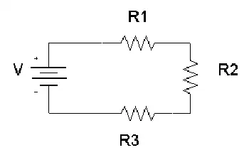
To calculate the total R in a series circuit, the individual resistances of each resistor are added together. The formula to calculate the equivalent resistance in a series connection is Rtotal = R1 + R2 + R3 + ..., where R1, R2, R3, and so on, represent the individual resistances of each resistor in the circuit.

Ohm's law also applies to series circuits, where the current through each resistor is the same, but the voltage across each resistor is proportional to its R. The total voltage across the series combination of resistors equals the sum of the voltage drops across each resistor.

It is essential to note that the total resistance in a series circuit is always greater than the resistance of any individual resistor in the circuit, due to the cumulative effect of each resistor's resistance.

On the other hand, resistors connected in parallel result in a parallel circuit. The equivalent R of a parallel circuit is calculated differently from a series connection. Instead of adding the individual resistances, the reciprocal of each R is added, and the resulting value is inverted to obtain the equivalent resistance.


R in Series - Parallel

When you place R-I-S, their ohmic values add up arithmetically to reach the total (or net) R.

We can connect a series of resistors (equal to the sum of the individual resistances of a parallel circuit), all having identical ohmic values, in parallel sets of series networks or series sets of parallel networks. When we do either of these things, we create a series-parallel network that can significantly increase the total power-handling capacity of the network compared to the power-handling capacity of a single parallel resistor.


Fig. 4-14. Three resistors in series. 

Sometimes, the total single equivalent R of the combination circuit in a series-parallel network equals the value of any one of the resistors. This always happens if the parallel branches or parallel combinations of the connection components are all identical and are arranged in a network called an n-by-n (or n x n) matrix. That means when n is a whole number, we have n series sets of n resistors connected in parallel, or else we have n parallel sets of n resistors connected in series in the circuit. These two arrangements yield the same practical result for electrical circuits.

A combination of series parallel combinations array of n by n resistors, all having identical ohmic values and identical power ratings, will have n2 times the power-handling capability of any resistor by itself. For example, a 3 x 3 series-parallel matrix of 2 W resistors can handle up to 32 x 2 = 9 x 2 = 18 W. If we have a 10 x 10 array of 1/2 W resistors, then it can dissipate up to 102 x 1/2 = 50 W. We multiply the power-handling capacity of each individual resistor by the total number of resistors in the matrix.

The above-described scheme works if, but only if, all of the resistors have identical ohmic values according to ohms law and identical power-dissipation ratings in terms of total voltage drops when the sum of the voltage drops across each resistor. If the resistors have values that differ even a little bit from one another, one of the components will likely draw more current than it can withstand, so that it will burn out, no matter the voltage source. Then the current distribution in the network will change further, increasing the likelihood that a second resistor will fail, and maybe more.

If you need a resistor that can handle 50 W, and a certain series-parallel connection of the network will handle 75 W, that's fine. But you should not "push your luck" and expect to get away with using a network that will handle only 48 W in the same application. You should allow some extra tolerance, say 10 per cent over the minimum rating. If you expect the network to dissipate 50W, you should build it to handle 55W or a bit more. You don't have to use "overkill," however. You'll waste resources if you cobble together a network that can handle 500W when you only expect it to cope with 50W—unless that's the only convenient combination you can make with available resistors.


Related Articles


View more

Power Factor Explained

Electrical systems depend on efficiency to operate safely and cost-effectively. One key indicator of that efficiency is power factor, which measures how effectively electrical energy is converted into useful work.

Power Quality Analysis Training

Power Factor Training

Request a Free Power Quality Training Quotation

Poor performance in this area leads to wasted energy, increased utility costs, and potential system stress. Managing it correctly can significantly improve overall reliability and lower expenses. To understand the foundation, see our detailed overview on what is power factor.


What is Power Factor?

In an AC circuit, managing efficiency often involves addressing issues caused by poor power factor. One common solution is to install capacitor banks, which help counteract the effects of inductive loads and improve the electrical system's power factor. However, when too much capacitance is introduced, it can result in a leading power factor, which may also create complications. Equipment that generates strong magnetic fields, such as motors and transformers, often disrupts the balance between real and apparent energy, reducing the ratio of power to apparent. Modern switched-mode supplies complicate matters further by introducing harmonic distortion into the energy supply, making it even more essential to monitor and correct the system regularly.


The Power Triangle visually represents the relationship between real power (kW), reactive power (kVAR), and apparent power (kVA) in an AC system. It highlights how a lower reactive component improves the overall system efficiency. In an AC circuit, real power (kW) performs useful work, reactive power (kVAR) supports magnetic fields, and apparent power (kVA) is the vector sum of the two.


How to Measure and Calculate Power Factor

Determining your system's performance begins with accurate measurement. Professionals use methods that involve real and apparent energy values, based on voltage and current readings.

To learn step-by-step techniques, visit our guide on how to calculate power factor. For the precise mathematical method, review the power factor formula.

You can also explore practical methods for finding power factor, which include using wattmeters, ammeters, and other field instruments.


Essential Tools for Performance Analysis

Accurately monitoring load conditions requires specialized equipment. Depending on the system's complexity, technicians may use portable meters, online analyzers, or built-in monitoring tools.

If you need a quick starting point, our power factor calculator simplifies the process.

For more detailed measurements, explore the capabilities of a power factor meter, designed for professional-grade accuracy.


Common Challenges in Electrical Systems

System inefficiencies often result from loads that are inductive or capacitive, creating phase shifts between voltage and current.

Inductive loads typically cause a lagging power factor, a frequent issue in industrial environments.

If you're dealing with capacitive loads or comparing system behaviors, you’ll find insights in leading vs lagging power factor.

Addressing these challenges early improves operational stability and reduces financial penalties from utilities.


Practical Methods to Improve Efficiency

Once a system's weaknesses are identified, targeted improvements can restore optimal conditions. Correction involves devices that realign the energy usage balance.

For an overview of different strategies, see power factor correction.

Installing a power factor correction capacitor is often the most straightforward method for load balancing.

For more dynamic systems, using an automatic power factor controller ensures continuous adjustments based on varying demands.


Why Unity Is the Ideal Goal

Achieving a unity rating, or a value of 1.0, means that all supplied energy is used effectively without waste.
Maintaining this condition ensures maximum cost savings, better equipment lifespan, and compliance with utility standards.

Discover the benefits and techniques by visiting unity power factor.


Measure, Monitor, and Manage for Long-Term Benefits

Improving the performance of your electrical system starts with regular monitoring, accurate measurement, and appropriate corrective action.
Whether you are troubleshooting existing problems or designing new systems, using the right tools and knowledge will keep operations running at peak power factor.


FAQ: Power Factor Questions


What causes a poor power factor?

Poor load balancing is typically caused by inductive loads like motors, transformers, and fluorescent lighting. These devices create magnetic fields that delay current flow, leading to a lagging power factor and wasted energy.


How much can a facility save by improving its power factor?

Improving system performance can reduce utility demand charges by 20% to 50% in some cases. It also decreases line losses, enhances system capacity, and extends equipment life, leading to significant operational savings.


What penalties apply for poor power factor?

Many utilities impose financial penalties if a facility’s reactive energy drops below a set threshold, often around 0.90. These charges can add thousands of dollars per year to an electric bill, making correction measures highly cost-effective.


What is a good power factor rating?

A good rating is typically above 0.95. The closer it is to 1.0, the more efficiently the system operates.


How often should I check my system's power factor?

It’s best to monitor it monthly, especially if your facility has changing load profiles throughout the year.


Can low power factor damage equipment?

While it may not cause direct damage, poor performance increases heating and losses, leading to premature wear and higher energy bills.


Are capacitors the only way to improve power factor?

No. Besides capacitors, active filters and automated correction devices like automatic power factor controllers offer flexible solutions.


What industries are most affected by poor load performance?

Industrial manufacturing, commercial buildings with heavy HVAC systems, and water treatment facilities are commonly impacted.


Related Articles


View more

Capacitors Explained

Capacitors store electrical energy via a dielectric, offering capacitance for filtering, smoothing, and decoupling in AC/DC circuits, RC networks, and power supplies, spanning ceramic, film, and electrolytic types with distinct impedance profiles.


What Are Capacitors?

Capacitors store charge using a dielectric, providing capacitance for filtering, timing, and decoupling in circuits.

✅ Types: ceramic, film, tantalum, electrolytic; surface-mount or through-hole

✅ Functions: decoupling, bulk energy storage, timing, AC coupling

✅ Key specs: capacitance, voltage rating, ESR/ESL, tolerance, ripple


Capacitors for Power Factor Correction

It is desirable to add shunt capacitors in the load area to supply the lagging component of current with a positive negative charging electrons. The cost is frequently justified by the value of circuit and substation capacity released and/or reduction in losses. Installed cost of shunt capacitors is usually least on primary distribution systems and in distribution substations. For foundational context, see what a capacitor is to understand reactive power roles.

The application of shunt capacitors to a distribution feeder produces a uniform voltage boost per unit of length of line, out to its point of application. Therefore, it should be located as far out on the distribution system as practical, close to the loads requiring the kilovars. There are some cases, particularly in underground distribution, where secondary capacitors are economically justified despite their higher cost per kilovar. The placement effectiveness also depends on capacitance characteristics relative to feeder impedance.

Development of low-cost switching equipment for capacitors has made it possible to correct the power factor to a high value during peak-load conditions without overcorrection during light-load periods. This makes it possible for switched capacitors to be used for supplementary voltage control. Time clocks, temperature, electric charge voltage, current flows, and kilovar controls are common actuators for high frequency capacitor switching. Utilities typically choose among several types of capacitors to balance switching duty and reliability.

Capacitor Installations

Capacitors for primary systems are available in 50- to 300-kvar single phase units suitable for pole mounting in banks of 3 to 12 units. Capacitors should be connected to the system through fuses so that a capacitor failure will not jeopardize system reliability or result in violent case rupture. When voltage ratings limit a single unit, engineers connect capacitors in series to distribute stress effectively.


Effect of Shunt Capacitors on Voltage

Proposed permanently connected capacitor applications should be checked to make sure that the voltage to some customers will not rise too high during light-load periods. Switched capacitor applications should be checked to determine that switching the capacitor bank on or off will not cause objectionable flicker in electronics. Selecting appropriate sizes in the standard unit of capacitance helps manage voltage rise and flicker.


Effect of Shunt Capacitors on Losses

The maximum loss reduction on a feeder with distributed load is obtained by locating positively negatively capacitor banks on the feeder where the capacitor kilovars is equal to twice the load kilovars beyond the point of installation. This principle holds whether one or more than one capacitor bank is applied to a feeder. To meet kvar targets with modular banks, utilities often add capacitance in parallel so reactive output scales predictably.

Capacitor kilovars up to 70% of the total kiovar load on the feeder can be applied as one bank with little sacrifice in the maximum feeder-loss discharge reduction possible with several capacitor banks.

A rule of thumb for locating a single capacitor bank on a feeder with uniformly distributed loads is that the maximum loss reduction can be obtained when the capacitor kilovars of the bank is equal to two-thirds of the kilovar load on the feeder. This bank should be located two-thirds of the distance out on the distributed feeder portion for object charging. Deviation of the capacitor bank location from the point of maximum loss reduction by as much as 10 per cent of the total feeder length does not appreciably affect the loss benefit. Therefore, in practice, in order to make the most out of the capacitor's loss reduction and voltage benefits, it is best to apply the capacitor bank just beyond the optimum loss-reduction location.

Batteries and capacitors seem similar as they both store and release electrical energy. However, there are crucial differences between them that impact their potential electronic applications due to how they function differently, depending on insulator material.


Supercapacitors

A capacitor battery aligns the molecules of a dielectric across an electric field to store energy. A supercapacitor aligns the charging of an electrolyte on either side of an insulator to store a double-layer charge.

Electrolytic capacitors consist of two or more conductive capacitors plate, separated by a dielectric. When an electric current enters the capacitor, the dielectric stops the flow and a charge builds up and is stored in an electric field between the metallic plates. Each capacitor is designed to have a particular capacitance (energy storage). When a capacitor is connected to an external circuit, a current will rapidly discharge. Plate area, separation, and dielectric constant together determine capacitance and thus energy density.

In a supercapacitor, there is no dielectric between conducting plates; rather, there is an electrolyte and a thin insulator such as cardboard or paper. When a current is introduced to the supercapacitor, ions build on either side of the insulator to generate a double layer of charge, no matter the capacitor charged. Supercapacitors are limited to low voltages, but very high capacitance frequencies, as a high voltage would break down the electrolyte. 


Batteries

There are different types of capacitor batteries, which detemine the capacitance of a capacitor. Different battery types are distinguished by their chemical makeup. The chemical unit, called the cell, contains three main parts; a positive terminal called the cathode, negative terminal called the anode, and the electrolyte. Batteries store electric energy. The battery charges and discharges through a chemical reaction that generates a voltage. The store of charge in the battery is able to provide a consistent DC voltage. In rechargeable batteries, the chemical energy that is converted into electricity can be reversed using an outside electrical energy to restore the charge of capacitors storing power in the batteries.


Related Articles

View more

Capacitance Explained

Capacitance: Understanding the Ability to Store Electricity

Capacitance is an essential concept in electrical circuits, and it describes the ability of a capacitor to store electrical energy. Capacitors are electronic components used in many circuits to perform various functions, such as filtering, timing, and power conversion. Capacitance is a measure of a capacitor's ability to store electrical energy, and it plays a crucial role in the design and operation of electrical circuits. This article provides an overview of capacitance, including its definition, SI unit, and the difference between capacitor and capacitance.


What is Capacitance?

Capacitance is the ability of a capacitor to store electrical charge. A capacitor consists of two conductive plates separated by a dielectric material. The conductive plates are connected to an electrical circuit, and the dielectric material is placed between them to prevent direct contact. When a voltage source is applied to the plates, electrical charge builds up on the surface of the plates. The amount of charge that a capacitor can store is determined by its capacitance, which depends on the size and distance between the plates, as well as the dielectric constant of the material.

The energy storing capability of a capacitor is based on its capacitance. This means that a capacitor with a higher capacitance can store more energy than a capacitor with a lower capacitance. The energy stored in a capacitor is given by the formula:

Energy (Joules) = 0.5 x Capacitance (Farads) x Voltage^2

The ability to store energy is essential for many applications, including filtering, timing, and power conversion. Capacitors are commonly used in DC circuits to smooth out voltage fluctuations and prevent noise. They are also used in AC circuits to filter out high-frequency signals.


What is Capacitance and the SI Unit of Capacitance?

Capacitance is defined as the ratio of the electrical charge stored on a capacitor to the voltage applied to it. The SI unit of capacitance is the Farad (F), which is defined as the amount of capacitance that stores one coulomb of electrical charge when a voltage of one volt is applied. One Farad is a relatively large unit of capacitance, and most capacitors have values that are much smaller. Therefore, capacitors are often measured in microfarads (µF) or picofarads (pF).

The capacitance of a capacitor depends on several factors, including the distance between the plates, the surface area of the plates, and the dielectric constant of the material between the plates. The dielectric constant is a measure of the ability of the material to store electrical energy, and it affects the capacitance of the capacitor. The higher the dielectric constant of the material, the higher the capacitance of the capacitor.


What is the Difference Between Capacitor and Capacitance?

Capacitor and capacitance are related concepts but are not the same thing. Capacitance is the ability of a capacitor to store electrical energy, while a capacitor is an electronic component that stores electrical charge. A capacitor consists of two conductive plates separated by a dielectric material, and it is designed to store electrical charge. Capacitance is a property of a capacitor, and it determines the amount of electrical charge that the capacitor can store. Capacitance is measured in Farads, while the capacitor is measured in units of capacitance, such as microfarads (µF) or picofarads (pF).


What is an Example of Capacitance?

One example of capacitance is a common electronic component known as an electrolytic capacitor. These capacitors are used in a wide range of electronic circuits to store electrical energy, filter out noise, and regulate voltage. They consist of two conductive plates separated by a dielectric material, which is usually an electrolyte. The electrolyte allows for a high capacitance, which means that these capacitors can store a large amount of electrical energy.

Another example of capacitance is the human body. Although the capacitance of the human body is relatively small, it can still store a significant amount of electrical charge. This is why people can sometimes feel a shock when they touch a grounded object, such as a metal doorknob or a handrail. The capacitance of the human body is affected by several factors, including the size and shape of the body, as well as the material and proximity of the objects it comes into contact with.

View more

Sign Up for Electricity Forum’s Newsletter

Stay informed with our FREE Newsletter — get the latest news, breakthrough technologies, and expert insights, delivered straight to your inbox.

Electricity Today T&D Magazine Subscribe for FREE

Stay informed with the latest T&D policies and technologies.
  • Timely insights from industry experts
  • Practical solutions T&D engineers
  • Free access to every issue

Live Online & In-person Group Training

Advantages To Instructor-Led Training – Instructor-Led Course, Customized Training, Multiple Locations, Economical, CEU Credits, Course Discounts.

Request For Quotation

Whether you would prefer Live Online or In-Person instruction, our electrical training courses can be tailored to meet your company's specific requirements and delivered to your employees in one location or at various locations.