Power System Analysis Explained

By R.W. Hurst, Editor


Power System Analysis enables load flow studies, fault calculations, stability assessment, state estimation, and contingency analysis for grids, integrating SCADA data, protection coordination, and reliability planning to optimize transmission, distribution, and generation performance.


What Is Power System Analysis?

Power System Analysis models grid behavior to ensure stability, reliability, efficiency, and secure operation.

✅ Load flow, short-circuit, and transient stability studies

✅ State estimation, SCADA integration, and contingency analysis

✅ Protection coordination, reliability assessment, and optimization


Power system analysis (PSA) is an essential electrical system component. It helps to ensure that the electrical system operates efficiently, reliably, and safely. Power flow analysis, fault study, stability investigation, renewable energy integration, grid modernization, and optimization techniques are all essential concepts in PSA. As our society continues to rely heavily on electricity, PSA will remain a vital tool for ensuring the stability and reliability of the electrical system. For foundational context on how electricity underpins these studies, see this primer on what electricity is and how it behaves.

One of the critical concepts in PSA is power system modelling. Modelling is creating a mathematical model of the electrical system. This model includes all the system components, such as generators, transformers, transmission lines, and distribution networks. Modelling is essential as it provides a detailed understanding of the system's workings. Engineers commonly begin by drafting a single-line diagram to visualize component interconnections and power paths.

Another critical concept in PSA is power flow investigation, also known as load flow investigation. Power flow analysis calculates the electrical system's voltages, currents, and power flows under steady-state conditions. A power flow study helps determine whether the electrical system can deliver electricity to all the loads without overloading any system component. The results of the power flow investigation are used to plan the system's expansion and ensure that it operates efficiently and reliably. In practice, load-flow outputs are interpreted within the broader context of electric power systems to validate voltage profiles and thermal limits.

Fault study is another crucial component of PSA. A fault study is a process of analyzing the system's behaviour during a fault condition. This needs a short circuit analysis. A fault is abnormal when the system has a short or open circuit. A fault study helps to determine the fault's cause and develop strategies to prevent or mitigate the effects of faults in the future.

Stability investigation is also an important aspect of PSA. Stability investigation is the process of analyzing the system's behaviour under dynamic conditions. For example, the system is subject to dynamic disturbances, such as sudden load or generator output changes, which can cause instability. Stability investigation helps ensure the system can withstand these disturbances and operate reliably.

The transient investigation is another key concept in PSA. The transient study analyzes the electrical system's behaviour during transient conditions, such as switching operations or lightning strikes. A brief investigation helps ensure the system can withstand these transient conditions and operate reliably.

Renewable energy integration is an emerging concept in PSA. As more renewable energy sources, such as wind and solar power, are integrated into the energy system, PSA becomes increasingly essential to ensure the stability and reliability of the electrical system. Understanding how generation mixes are formed benefits from a primer on how electricity is generated across thermal, hydro, and renewable technologies.

Grid modernization is also a crucial aspect of PSA. As the system ages, it becomes increasingly important to modernize the grid to ensure that it can meet the demands of modern society. Therefore, PSA is used to develop strategies to modernize the grid and ensure it operates efficiently, reliably, and safely. Many modernization roadmaps align with the evolving architecture of the electricity grid as utilities adopt automation, advanced metering, and distributed resources.

Finally, protection coordination and optimization techniques are essential components of PSA. Protection coordination involves developing strategies to protect the electrical system from faults and other abnormal conditions. Optimization techniques involve developing strategies to optimize the system's operation and ensure it operates efficiently and reliably. Because reactive power and losses affect dispatch, monitoring and improving power factor can materially enhance system efficiency.


What is power system analysis, and why is it important?

PSA analyzes the electrical system to ensure it operates efficiently, reliably, and safely. Therefore, it is crucial to identify potential problems before they occur and develop strategies to prevent or mitigate the effects of these problems. In addition, PSA is important because it helps ensure that the electrical system can meet the demands of modern society, which relies heavily on electricity.


How is power flow analysis performed?

Power flow analysis, or load flow analysis, is performed using a mathematical model. The model includes all the power system components, such as generators, transformers, transmission lines, and distribution networks. A power flow study calculates the electrical system's voltages, currents, and power flows under steady-state conditions. The results of the power flow investigation are used to plan the electrical system's expansion and ensure that it operates efficiently and reliably. These studies also quantify reactive power behavior, making concepts like what power factor is directly applicable to planning and operations.


What is fault analysis, and how is it used?

Fault analysis is analyzing the system's behaviour during a fault condition. A fault is abnormal when the system has a short or open circuit. A fault study is used to determine the fault's cause and develop strategies to prevent or mitigate the effects of faults in the future. Fault analysis is crucial in ensuring the safety and reliability of the electrical system.


What are the different stability study techniques used?

Several stability investigation techniques are used in PSA to measure transient, small-signal, and voltage stability. Transient stability is used to analyze the behaviour of the distribution under dynamic conditions, such as sudden changes in load or generator output. Small-signal stability measurement analyzes the system's behaviour under small disturbances. Finally, voltage stability measurement is used to analyze the system's behaviour under steady-state conditions and determine the system's voltage limits.


How does renewable energy integration affect power system analysis?

Renewable energy integration is an emerging concept in PSA. As more renewable energy sources, such as wind and solar power, are integrated into the electrical system, PSA becomes increasingly essential to ensure the stability and reliability of the system. Renewable energy sources are intermittent, which can cause fluctuations in the system. PSA is used to develop strategies to integrate renewable energy sources into the system while ensuring its stability and reliability.


What are the challenges of grid modernization, and how does power system analysis help overcome them?

Grid modernization is a crucial aspect of PSA. As the system ages, it becomes increasingly important to modernize the grid to ensure that it can meet the demands of modern society. Grid modernization involves upgrading the system to incorporate new technologies, such as smart grid technologies and renewable energy sources. The challenges of grid modernization include the need for new infrastructure, the integration of new technologies, and new regulatory frameworks. PSA is used to develop strategies to overcome these challenges and to ensure that the electrical system operates efficiently, reliably, and safely.


How can optimization techniques improve system efficiency and reliability in power system analysis?

Optimization techniques can be used in PSA to improve system efficiency and reliability. These techniques involve developing strategies to optimize the system's operation and ensure it operates efficiently and reliably. For example, optimization techniques can determine the optimal generation and transmission of power, improve load forecasting, and develop strategies to reduce energy consumption. PSA is crucial in developing and implementing these optimization techniques, which help improve the electrical system's overall efficiency and reliability, leading to a more sustainable and cost-effective electrical power system.

Related News

What is Open Circuit Voltage? Explained

Open circuit voltage is the potential difference measured across the terminals of a device when no external load is applied. Common in batteries, solar cells, and electrical circuits, it helps evaluate performance, efficiency, and voltage characteristics.


What is Open Circuit Voltage?

It is the maximum voltage measured across terminals when no current flows in the circuit, providing a baseline for performance evaluation.

✅ Indicates battery and solar cell efficiency

✅ Helps assess electrical circuit performance

✅ Defines voltage without current flow

What is open circuit voltage? Often abbreviated as OCV, is an essential concept within electrical engineering, particularly relevant to professionals handling electrical systems or devices. Defined as the electrical potential difference between two points in a circuit when no current flows, OCV represents the maximum voltage achievable without applying a load. For electrical workers, understanding OCV is crucial, as it enables the evaluation of power sources and the identification of potential issues within a circuit before engaging with it under load. Knowledge of OCV benefits electrical workers by providing insights into system readiness, ensuring operational safety, and facilitating troubleshooting for optimal equipment performance. Understanding basic electricity is the foundation for grasping what open circuit voltage means, since it defines how voltage behaves when no current flows.


Determining Open Circuit Voltage

OCV can be measured using instruments like digital multimeters, which provide readings of the maximum electrical potential in the circuit. When conducting a test, it’s essential to measure the resistance between two terminals with no current flow. For instance, if a circuit is connected to a 12-volt battery with no load, the multimeter will display the OCV, which typically matches the battery’s maximum voltage. Similarly, in a solar cell, the OCV provides an indication of the maximum power it can generate when fully charged. Such measurements are helpful in evaluating the state of charge and operational status, providing valuable data to maintain system health. A solid grasp of electrical resistance is also critical, as resistance affects how potential differences are measured when a circuit is open.


Open Circuit Voltage Test

The open-circuit voltage test, also known as the no-load test, is a standard procedure in electrical engineering for assessing a power source's condition when it is not under load. In this test, an engineer connects a voltmeter to the terminals of a circuit to measure the OCV. This process is valuable for detecting issues such as short circuits, high resistance, or compromised wiring, which can lead to performance problems. The results from this test enable electrical professionals to detect weak points in a circuit before it operates under load, ensuring smoother and safer functionality. Open-circuit voltage is directly related to capacitance, as capacitors store electrical potential that can be measured under no-load conditions.


Applications of Open Circuit Voltage 

In practical applications, open circuit voltage is not just a measurement but a vital diagnostic tool. For example, in renewable energy systems, engineers often assess solar cell efficiency by examining its OCV. A solar cell’s OCV indicates its potential output, enabling accurate calculations of energy capacity and state of charge. Understanding OCV also aids in selecting voltage levels appropriate for different components, especially in high-voltage systems where matching component capacity is essential. In this way, OCV serves as a baseline for electrical potential, enabling engineers to optimize systems for both performance and safety. Engineers often compare OCV with direct current behavior, where stable voltages are easier to measure without the influence of alternating loads.

The concept of OCV has safety implications. By knowing the maximum potential voltage in a circuit before activating it, engineers can implement safeguards to avoid overloads or shorts that might occur under load. In electrical troubleshooting, measuring OCV allows for the identification of circuits that aren’t performing optimally, pinpointing faults or abnormal resistance that could lead to hazards. Hence, for electrical workers, mastering OCV measurement is not only about system performance but also about adhering to safety standards that protect both personnel and equipment.


Frequently Asked Questions


What is Open Circuit Voltage?

Open circuit voltage refers to the electrical potential, or maximum voltage, present between two conductors in a circuit when there is no active current flowing. This concept is applicable to both direct current (DC) and alternating current (AC) circuits. In DC systems, the OCV remains stable at a maximum level when no load is connected. In AC circuits, OCV may vary depending on factors such as load fluctuations and circuit design. The measurement of OCV is crucial for determining the performance of various devices, including solar cells, where the state of charge can be observed by checking the OCV. Electrical engineers and technicians can use this information to diagnose issues and assess the readiness of systems for operation. In 3-phase electricity systems, knowing the open circuit voltage helps engineers ensure balance and reliability before load conditions are applied.


Why Open Circuit Voltage Matters

For anyone working in electrical engineering, understanding open-circuit voltage is essential for designing and troubleshooting systems. OCV indicates the maximum voltage a circuit can sustain, helping engineers select compatible components and design for peak efficiency. For instance, when assessing a solar cell, the OCV helps identify the electrical potential it can generate without applying any load. In this way, OCV is a guide to the expected performance under load-free conditions, ensuring that devices will perform within specified limits when placed in actual operation. The concept also closely relates to active power, as OCV provides a baseline for calculating the amount of real power a system can deliver once current begins to flow.


Does open circuit voltage change with temperature?

Yes, temperature can affect open circuit voltage. For example, solar cells typically show a decrease in OCV as temperature rises, which impacts efficiency and energy output.


Is the open circuit voltage always equal to the source voltage?

Not always. While OCV often matches the nominal source voltage, internal resistance, aging, or chemical changes in a battery can cause the measured value to differ slightly.


Can open circuit voltage predict battery health?

OCV can give an indication of a battery’s state of charge, but it is not a complete measure of health. Additional tests, such as load testing, are needed to assess the overall condition.


How does open circuit voltage relate to safety testing?

Measuring OCV before energizing equipment enables engineers to confirm expected voltage levels and prevent hazardous conditions that may arise under load.


Is open circuit voltage used in AC systems as well as DC?

Yes, OCV applies to both AC and DC systems. In AC circuits, variations may occur depending on the design and frequency, whereas DC systems typically provide a stable maximum value.


What is open circuit voltage? Open circuit voltage is more than just a technical measurement; it is a vital reference point for understanding the behavior of batteries, solar cells, and electrical circuits under no-load conditions. By measuring OCV, electrical professionals gain valuable insights into efficiency, reliability, and safety before current flows, ensuring systems are prepared for real-world operation. Whether applied in renewable energy, troubleshooting, or equipment testing, open circuit voltage provides the foundation for sound engineering decisions and safer electrical practices.


Related Articles


View more

Electrical Resistance Definition Explained

Electrical resistance definition explains how materials oppose current flow in circuits, measured in ohms, linked to voltage, resistivity, conductor geometry, temperature, and impedance, governed by Ohm's law and SI units in electronics.


What Is Electrical Resistance Definition?

It is the measure of how a material opposes electric current, equal to voltage divided by current and measured in ohms.

✅ Measured in ohms; per Ohm's law, resistance R equals voltage V over current I.

✅ Depends on material resistivity, length, cross-sectional area, and temperature.

✅ Key in circuit analysis, power dissipation, signal integrity, and safety.


Electrical Resistance Definition: ER occurs in an electrical circuit when current-carrying charged particles collide with fixed particles that make up the structure of the conductors. Resistance is measured in ohm. Resistance is the ohm w. Resistance occurs in every part of a circuit, including wires and especially power transmission lines. For a concise overview, see this introduction to electrical resistance to reinforce key definitions.

Dissipation of electric energy in the form of heat affects the amount of driving voltage required to produce a given current through the circuit. In fact, volts are mesured across a circuit divided by the current I (amperes) through that circuit defines quantitatively the amount of electrical resistance R. The ohm is the common unit of electrical resistance, equivalent to one volt per ampere and represented by the capital Greek letter omega, Ω. The electrical resistance of a wire is directly proportional to its length and inversely proportional to its cross-sectional area. Resistance also depends on the material of the conductor. For instance, the resistance of a conductor generally increases with increasing temperature the resistivity. This is why some conductors have almost zero resistance when cooled to extremely low temperatures, as is the case with superconductors, because of the relative resistivity of metals. There is a temperature coefficient of resistivity. If you need a refresher on potential difference and its role in circuits, review this explanation of voltage to connect the concepts.

Alternating-current resistors for current measurement require further design consideration. For example, if the resistor is to be used for current-transformer calibration, its ac resistance must be identical with its dc resistance within 1/100th% or better, and the applied voltage difference between its voltage terminals must be in phase with the current through it within a few tenths of a minute. Thin strips or tubes of resistance material are used to limit eddy currents and minimize "skin" effect, the current circuit must be arranged to have small self-inductance, and the leads from the voltage taps to the potential terminals should be arranged so that, as nearly as possible, the mutual inductance between the voltage and current circuits opposes and cancels the effect of the self-inductance of the current circuit. In (a) a metal strip has been folded into a very narrow U; in (b) the current circuit consists of coaxial tubes soldered together at one end to terminal blocks at the other end; in (c) a straight tube is used as the current circuit, and the potential leads are snugly fitting coaxial tubes soldered to the resistor tube at the desired separation and terminating at the center. These design choices are also easier to contextualize by comparing common types of resistors used for precise AC measurements.

Electrical Resistance coils consist of insulated resistance copper wire wound on a bobbin or winding form, hard-soldered at the ends to copper terminal wires. Metal tubes are widely used as winding form for dc resistors because they dissipate heat more readily than insulating bobbins, but if the resistor is to be used in ac measurements, a ceramic winding form is greatly to be preferred because it contributes less to the phase-defect angle of the resistor. The resistance wire ordinarily is folded into a narrow loop and wound bifilar onto the form to minimize inductance. This construction results in considerable associated capacitance of high-resistance coils, for which the wire is quite long, and an alternative construction is to wind the coil inductively on a thin mica or plastic card. The capacitive effect is greatly reduced, and the inductance is still quite small if the card is thin. When specifying coil assemblies, it helps to recall the standardized unit of electrical resistance so ratings and tolerances are interpreted consistently.

Resistors in which the wire forms the warp of a woven ribbon have lower time constants than either the simple bifilar- or card-wound types. Manganin is the resistance material most generally employed, but Evanohm and similar alloys are beginning to be extensively used for very high resistance coils. Enamel or silk is used to insulate the wire, and the finished coil is ordinarily coated with shellac or varnish to protect the wire from the atmosphere. Such coatings do not completely exclude moisture, and dimensional changes of insulation with humidity will result in small resistance changes, particularly in high resistances where fine wire is used. Material behavior, moisture effects, and long term stability are discussed further in this broader overview of electrical resistance for additional context.

Electrical Resistance boxes usually have two to four decades of resistance so that with reasonable precision they cover a considerable range of resistance, adjustable in small steps. For convenience of connection, terminals of the individual resistors are brought to copper blocks or studs, which are connected into the circuit by means of plugs or of dial switches using rotary laminated brushes; clean, well-fitted plugs probably have lower resistance than dial switches but are much less convenient to use. The residual inductance of decade groups of coils due to switch wiring, and the capacitance of connected but inactive coils, will probably exceed the residuals of the coils themselves, and it is to be expected that the time constant of an assembly of coils in a decade box will be considerably greater than that of the individual coils. Understanding how series and parallel combinations set the equivalent resistance will inform how decade boxes are deployed in complex networks.

Measurement of resistance is accomplished by a variety of methods, depending on the magnitude of the resistor and the accuracy required. Over the range from a few ohms to a megohm or more, an ohmmeter may be used for an accuracy of a few percent. A simple ohmmeter may consist of a milliammeter, dry cell, and resistor in a series circuit, the instrument scale being marked in resistance units, if you obey ohm law. For a better value, the voltage drop is measured across the resistor for a measured or known current through it. Here, accuracy is limited by the instrument scales unless a potentiometer is used for the current and voltage measurements. The approach is also taken in the wide variety of digital multimeters now in common use. Their manufacturers' specifications indicate a range of accuracies from a few percent to 10 ppm (0.001%) or better from the simplest to the most precise meters. Bridge methods can have the highest accuracy, both because they are null methods in which two or more ratios can be brought to equality and because the measurements can be made by comparison with accurately known standards. For two-terminal resistors, a Wheatstone bridge can be used; for four-terminal measurements, a Kelvin bridge or a current comparator bridge can be used. Bridges for either two- or four-terminal measurements also may be based on resistive dividers. Because of their extremely high input impedance, digital voltmeters that be used with standard resistors in unbalanced bridge circuits of high accuracy. For quick reference during test planning, the fundamental resistance formula clarifies how R, V, and I are related under Ohm law.

Digital multi meters are frequently used to make low-power measurements of resistors in the range between a few ohms and a hundred megohms or so. Resolution of such instruments varies from 1% of full scale to a part per million of full scale. These meters generally use a constant-current source with a known current controlled by comparing the voltage drop on an internal "standard" resistor to the EMF produced by a Zener diode. The current is set at such a level as to make the meter direct-reading in terms of the displayed voltage; that is, the number displayed by the meter reflects the voltage drop across the resistor, but the decimal point is moved and the scale descriptor is displayed as appropriate. Multimeters typically use three or more fixed currents and several voltage ranges to produce seven or more decade ranges with the full-scale reading from 1.4 to 3.9 times the range. For example, on the 1000-0 range, full scale may be 3,999.999 Q. Power dissipated in the measured resistor generally does not exceed 30 mW and reaches that level only in the lowest ranges where resistors are usually designed to handle many times that power. The most accurate multimeters have a resolution of 1 to 10 ppm of range on all ranges above the 10-0 range. Their sensitivity, linearity, and short-term stability make it possible to compare nominally equal resistors by substitution with an uncertainty 2 to 3 times the least count of the meter. This permits their use in making very accurate measurements, up to 10 ppm, or resistors whose values are close to those of standards at hand. Many less expensive multimeters have only two leads or terminals to use to make measurements. In those cases, the leads from the meter to the resistor to be measured become part of the measured


Related Articles

View more

Understanding Current

Current is the flow of electric charge in circuits, defined by amperage, driven by voltage, limited by resistance, described by Ohm’s law, and fundamental to AC/DC power systems, loads, conductors, and electronic components.


What Is Current?

Current is charge flow in a circuit, measured in amperes and governed by voltage and resistance.

✅ Measured in amperes; sensed with ammeters and shunts

✅ Defined by Ohm’s law: I = V/R in linear resistive circuits

✅ AC alternates; DC is steady; sets power transfer P = V*I


Current is best described as a flow of charge or that the charge is moving. Electrons in motion make up an electric current. This electric current is usually referred to as “current” or “current flow,” no matter how many electrons are moving. Current is a measurement of a rate at which a charge flows through some region of space or a conductor. The moving charges are the free electrons found in conductors, such as copper, silver, aluminum, and gold. The term “free electron” describes a condition in some atoms where the outer electrons are loosely bound to their parent atom. These loosely bound electrons can be easily motivated to move in a given direction when an external source, such as a battery, is applied to the circuit. These electrons are attracted to the positive terminal of the battery, while the negative terminal is the source of the electrons. The greater amount of charge moving through the conductor in a given amount of time translates into a current. For a concise overview of how moving charges create practical circuits, see this guide to current electricity for additional context.


The System International unit for current is the Ampere (A), where


That is, 1 ampere (A) of current is equivalent to 1 coulomb (C) of charge passing through a conductor in 1 second(s). One coulomb of charge equals 6.28 billion billion electrons. The symbol used to indicate current in formulas or on schematics is the capital letter “I.” To explore the formal definition, standards, and measurement practices, consult this explanation of the ampere for deeper detail.

When current flow is one direction, it is called direct current (DC). Later in the text, we will discuss the form of current that periodically oscillates back and forth within the circuit. The present discussion will only be concerned with the use of direct current. If you are working with batteries or electronic devices, you will encounter direct current (DC) in most basic circuits.

The velocity of the charge is actually an average velocity and is called drift velocity. To understand the idea of drift velocity, think of a conductor in which the charge carriers are free electrons. These electrons are always in a state of random motion similar to that of gas molecules. When a voltage is applied across the conductor, an electromotive force creates an electric field within the conductor and a current is established. The electrons do not move in a straight direction but undergo repeated collisions with other nearby atoms. These collisions usually knock other free electrons from their atoms, and these electrons move on toward the positive end of the conductor with an average velocity called the drift velocity, which is relatively a slow speed. To understand the nearly instantaneous speed of the effect of the current, it is helpful to visualize a long tube filled with steel balls as shown in Figure 10-37. It can be seen that a ball introduced in one end of the tube, which represents the conductor, will immediately cause a ball to be emitted at the opposite end of the tube. Thus, electric current can be viewed as instantaneous, even though it is the result of a relatively slow drift of electrons. For foundational concepts that connect drift velocity with circuit behavior, review this basic electricity primer to reinforce the fundamentals.

Current is also a physical quantity that can be measured and expressed numerically in amperes. Electric current can be compared to the flow of water in a pipe. It is measureda at the rate in which a charge flows past a certain point on a circuit. Current in a circuit can be measured if the quantity of charge "Q" passing through a cross section of a wire in a time "t" (time) can be measured. The current is simply the ratio of the quantity of charge and time. Understanding current and charge flow also clarifies how circuits deliver electrical energy to perform useful work.


Electrical current is essentially an electric charge in motion. It can take either the form of a sudden discharge of static electricity, such as a lightning bolt or a spark between your finger and a ground light switch plate. More commonly, though, when we speak of current, we mean the more controlled form of electricity from generators, batteries, solar cells or fuel cells.  A helpful overview of static, current, and related phenomena is available in this summary of electricity types for quick reference.

We can think of the flow of electrons in a wire as the flow of water in a pipe, except in this case, the pipe of water is always full. If the valve on the pipe is opened at one end to let water into the pipe, one doesn't have to wait for that water to make its way all the way to the other end of the pipe. We get water out the other end almost instantaneously because the incoming water pushes the water that's already in the pipe toward the end. This is what happens in the case of electrical current in a wire. The conduction electrons are already present in the wire; we just need to start pushing electrons in one end, and they start flowing at the other end instantly. In household power systems, that push on conduction electrons alternates in direction as alternating current (AC) drives the flow with a time-varying voltage.


Current Formula

Current is rate of flow of negatively-charged particles, called electrons, through a predetermined cross-sectional area in a conductor.

 Essentially, flow of electrons in an electric circuit leads to the establishment of current.

q = relatively charged electrons (C)

t = Time

Amp = C/sec

Often measured in milliamps, mA


Related Articles

View more

Resistance in Series Explained

Resistance in series refers to the arrangement of individual resistors in a circuit, where the current flows through each resistor end to end. In this configuration, the total resistance (R) of the circuit is equal to the sum of the individual resistances, also known as the equivalent R.


What is Resistance in Series?

Resistance in series refers to a circuit configuration where resistors are arranged in a single path:

✅ Total resistance is the sum of all resistors in the circuit

✅ The same current flows through each resistor

✅ Voltage divides across each resistor based on its value

To calculate the total R in a series circuit, the individual resistances of each resistor are added together. The formula to calculate the equivalent resistance in a series connection is Rtotal = R1 + R2 + R3 + ..., where R1, R2, R3, and so on, represent the individual resistances of each resistor in the circuit.

Ohm's law also applies to series circuits, where the current through each resistor is the same, but the voltage across each resistor is proportional to its R. The total voltage across the series combination of resistors equals the sum of the voltage drops across each resistor.

It is essential to note that the total resistance in a series circuit is always greater than the resistance of any individual resistor in the circuit, due to the cumulative effect of each resistor's resistance.

On the other hand, resistors connected in parallel result in a parallel circuit. The equivalent R of a parallel circuit is calculated differently from a series connection. Instead of adding the individual resistances, the reciprocal of each R is added, and the resulting value is inverted to obtain the equivalent resistance.


R in Series - Parallel

When you place R-I-S, their ohmic values add up arithmetically to reach the total (or net) R.

We can connect a series of resistors (equal to the sum of the individual resistances of a parallel circuit), all having identical ohmic values, in parallel sets of series networks or series sets of parallel networks. When we do either of these things, we create a series-parallel network that can significantly increase the total power-handling capacity of the network compared to the power-handling capacity of a single parallel resistor.


Fig. 4-14. Three resistors in series. 

Sometimes, the total single equivalent R of the combination circuit in a series-parallel network equals the value of any one of the resistors. This always happens if the parallel branches or parallel combinations of the connection components are all identical and are arranged in a network called an n-by-n (or n x n) matrix. That means when n is a whole number, we have n series sets of n resistors connected in parallel, or else we have n parallel sets of n resistors connected in series in the circuit. These two arrangements yield the same practical result for electrical circuits.

A combination of series parallel combinations array of n by n resistors, all having identical ohmic values and identical power ratings, will have n2 times the power-handling capability of any resistor by itself. For example, a 3 x 3 series-parallel matrix of 2 W resistors can handle up to 32 x 2 = 9 x 2 = 18 W. If we have a 10 x 10 array of 1/2 W resistors, then it can dissipate up to 102 x 1/2 = 50 W. We multiply the power-handling capacity of each individual resistor by the total number of resistors in the matrix.

The above-described scheme works if, but only if, all of the resistors have identical ohmic values according to ohms law and identical power-dissipation ratings in terms of total voltage drops when the sum of the voltage drops across each resistor. If the resistors have values that differ even a little bit from one another, one of the components will likely draw more current than it can withstand, so that it will burn out, no matter the voltage source. Then the current distribution in the network will change further, increasing the likelihood that a second resistor will fail, and maybe more.

If you need a resistor that can handle 50 W, and a certain series-parallel connection of the network will handle 75 W, that's fine. But you should not "push your luck" and expect to get away with using a network that will handle only 48 W in the same application. You should allow some extra tolerance, say 10 per cent over the minimum rating. If you expect the network to dissipate 50W, you should build it to handle 55W or a bit more. You don't have to use "overkill," however. You'll waste resources if you cobble together a network that can handle 500W when you only expect it to cope with 50W—unless that's the only convenient combination you can make with available resistors.


Related Articles


View more

Short Circuit Definition

Understanding the short circuit definition and associated risks is crucial for ensuring electrical safety in homes and workplaces. By knowing the common causes of short circuits and employing preventive measures such as regular inspections, proper installation, and protective devices like circuit breakers and GFCIs, we can minimize the dangers associated with short circuits and create a safer environment for everyone.

A short circuit phenomenon occurs in electrical circuits and poses potential safety hazards. To better understand the short circuit definition, one must first become familiar with the fundamentals of electrical circuits. An electrical circuit is a closed loop through which electrical current flows, and it consists of various components such as power sources, conductors, and electrical devices. A short circuit happens when an unintended, low-resistance path is formed within the circuit, causing a significant increase in current flow.


What are the different types of short circuit?

There are three main types of short circuits, each with unique characteristics and implications. These types are categorized based on the specific components of the short circuit within an electrical system. Here are the three types of short circuits:


Phase-to-Phase

This type of short circuit, also known as a line-to-line short circuit, occurs when two or more phases of an electrical system come into contact with each other. For example, this can happen when insulation between the phases is damaged or worn out, or due to a fault in the equipment or wiring. A phase-to-phase short circuit rapidly increases current flow between the affected phases, which can cause significant damage to the electrical system and generate considerable heat.


Phase-to-Neutral

A phase-to-neutral short circuit, sometimes called a line-to-neutral short circuit, occurs when a live conductor (phase) comes into contact with the neutral conductor. This can occur due to damaged insulation, loose connections, or faulty equipment. In a phase-to-neutral short circuit, the current flows between the affected phase and the neutral conductor, resulting in an increased current flow and potential damage to the electrical system.


Phase-to-Ground

This type of short circuit, also known as a ground fault, occurs when a live conductor (phase) comes into contact with a grounded object or the earth. For example, this can happen when insulation is compromised, equipment is faulty, or wiring is damaged. A phase-to-ground short circuit results in a sudden surge of current as electricity takes the path of least resistance through the ground, posing a risk of damage to electrical components, fire, and electrical shock.


Each of these types can cause significant harm to electrical systems and pose potential safety hazards. Therefore, maintaining proper insulation and connections within electrical systems and implementing protective devices such as circuit breakers and ground fault circuit interrupters (GFCIs) is crucial to minimize the risks. In addition, regular inspections and maintenance of electrical equipment are also essential in ensuring the safe operation of electrical systems.

Now that we've laid the groundwork, let's delve deeper into the definition. A short circuit is defined as an abnormal connection between two nodes in an electrical circuit, allowing an excessive amount of current to flow through a low-resistance path. This can lead to various problems, including damage to electrical components, increased risk of fire, and even electrical shock.

So, how do short circuits occur? Several common causes include damaged or frayed electrical wires, improper connections, or faulty insulation. In addition, when conductive materials come into contact, they can create an unintended path for electrical current. This leads to a significant increase in current flow, resulting in a short circuit.

The dangers associated with short circuits cannot be overstated. When a short circuit occurs, it can generate intense heat, which poses a significant fire risk. Additionally, the increased current can cause conductor failure and damage to electrical components, leading to malfunctions and even total system failure. Furthermore, if an individual comes into contact with a short-circuited component, they could suffer from electrical shock, which can sometimes be fatal.

Preventing short circuits is a vital aspect of maintaining electrical safety. One of the most effective prevention methods is ensuring proper installation and maintenance of electrical systems. In addition, regular inspections should be conducted to identify and repair damaged wiring or faulty connections. Installing overload protection devices, such as circuit breakers or fuses, can also help protect against short circuits. These devices are designed to detect and interrupt the excessive current flow, thus mitigating the risk of damage or injury.

Circuit breakers play a crucial role in safeguarding electrical systems from the effects of short circuits. These devices are engineered to detect an unusually high current flow, which could indicate a short circuit or another fault. Once detected, the circuit breaker will automatically interrupt the current flow, isolating the affected section of the circuit and preventing further damage or injury.

To further understand short circuits, it's important to distinguish them from ground faults. While both phenomena involve an abnormal connection within an electrical circuit, a ground fault is a specific type of short circuit that occurs when a live conductor comes into contact with a grounded object or the earth. This can lead to a sudden current surge and pose similar risks, such as fire and electrical shock. However, ground faults can be detected and mitigated using specialized devices called ground fault circuit interrupters (GFCIs).

Remember, always be vigilant when dealing with electrical systems. If you are uncertain about a potential issue or unsure how to handle a situation, consult a licensed electrician for assistance. Electrical safety is everyone's responsibility, and understanding definition is a fundamental step in preventing accidents and promoting a safe environment.

View more

Watthour Meter Explained

A watthour meter measures electrical energy consumption in kilowatt-hours (kWh) for residential, commercial, and industrial applications, ensuring accurate billing, energy management, and compliance with utility standards.


What is a Watthour Meter?

✅ Measures total electrical energy in kilowatt-hours (kWh) over time

✅ Supports accurate billing, energy monitoring, and demand analysis

✅ Used in residential, commercial, and industrial revenue metering


Advancements in Watthour Meter Technology and Energy Measurement

Watthour meter technology plays a crucial role in modern electrical engineering and maintenance by providing accurate measurement and monitoring of energy consumption. These devices are indispensable for managing energy efficiency, optimizing power distribution, and ensuring compliance with regulatory standards. For electrical professionals, understanding how they operate and are maintained is essential to minimize energy losses and enhance the reliability of electrical systems. With the growing demand for precise energy data in both residential and industrial applications, staying informed about advancements in watthour meter technology is more important than ever. Understanding how a watthour is calculated helps clarify how a watthour meter tracks total energy usage for accurate billing. 


How Induction Type Single Phase Watt Hour Meters Work

Induction type meters, commonly used as single phase watt hour meters, provide accurate measurement of electrical energy consumption in residential and small commercial installations.

Your electric utility is not too interested in how much power you're consuming for one ap­pliance or even how much power a single household is drawing at any given time. By far the greater concern is the total energy that is used over a day, a week, a month or a year. Electrical energy is measured in watt-hours or, more commonly for utility pur­poses, in kilowatt-hours (kWh). The device that measures this consumption is the watt-hour meter or kilowatt-hour meter. For a deeper understanding of the units used in metering, see our guide on electrical energy and how it is measured in kilowatt-hours.

The most common method for measuring electrical energy is by using a small elec­tric motor device, whose speed depends on the current, and thereby on the power at a constant voltage. The number of turns of the motor shaft, in a given length of time, is di­rectly proportional to the number of watt hours consumed. The motor is placed at the point where the utility wires enter the house, apartment or building. This is usually at a point where the voltage is 234 V. This is split into some circuits with 234 V, for heavy-duty appliances such as the oven, washer and dryer, and the general household circuits for lamps, clock radios and television sets. The principles behind watthour meters are closely tied to basic electricity and the relationship between active power and time.


Understanding the Spinning Disk in Electromechanical Watthour Meters

You've surely seen the little disk in the utility meter going around and around, sometimes fast, other times slowly. Its speed depends on the power you're using. The total number of turns of this little disk, every month, determines the size of the bill you will get, as a function also, of course, of the cost per kilowatt hour for electricity.

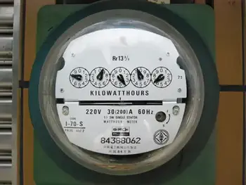
Kilo-watt-hour meters count the number of disk turns by means of geared, rotary drums or pointers. The drum-type meter gives a direct digital readout. The pointer type has several scales calibrated from 0 to 9 in circles, some going clockwise and others go­ing counterclockwise. Mechanical and electronic meters both rely on the concepts of electrical resistance and current to provide precise readings.


How to Read a Pointer-Type Watthour Meter Accurately

Reading a pointer-type utility meter is a little tricky because you must think in whatever direction (clockwise or counterclockwise) the scale goes. An example of a pointer-type utility meter is shown in Fig. 3-11. Read from left to right. For each little meter, take down the number that the pointer has most recently passed. Write down the rest as you go. The meter in the figure reads 3875 kWh. If you want to be really pre­cise, you can say it reads 3875-1/2 kWh. To place watt hour metering in historical context, explore our history of electricity page and learn how early meters evolved into today’s advanced devices.


Fig. 3-11 An example of a utility kilo-watthour meter. The reading is a little more than 3875 kWh.


Related Articles


View more

Sign Up for Electricity Forum’s Newsletter

Stay informed with our FREE Newsletter — get the latest news, breakthrough technologies, and expert insights, delivered straight to your inbox.

Electricity Today T&D Magazine Subscribe for FREE

Stay informed with the latest T&D policies and technologies.
  • Timely insights from industry experts
  • Practical solutions T&D engineers
  • Free access to every issue

Live Online & In-person Group Training

Advantages To Instructor-Led Training – Instructor-Led Course, Customized Training, Multiple Locations, Economical, CEU Credits, Course Discounts.

Request For Quotation

Whether you would prefer Live Online or In-Person instruction, our electrical training courses can be tailored to meet your company's specific requirements and delivered to your employees in one location or at various locations.