Electricity Generator
By William Conklin, Associate Editor
An Electricity generator converts mechanical energy to electrical power via electromagnetic induction, using a prime mover, an alternator, a stator, and a rotor, delivering a regulated AC/DC output, high efficiency, and stable voltage and frequency.
How an Electricity Generator Works
Electricity generators operate on a simple principle: when mechanical motion disturbs a magnetic field, it sets electrons in motion, producing usable electrical output. When a conductor moves through a magnetic field, electrons begin to drift, and that simple idea forms the basis of every generator in use today. Whether the machine is part of a wind turbine, a diesel unit on a construction site, or a large plant feeding the grid, the purpose never changes: convert motion into a usable electrical supply. Unlike fuels extracted from the ground, electricity is generated on demand, and generators remain among the most direct ways to produce it. Design choices for coil turns, flux, and rotational speed are discussed in how electricity is generated with practical examples.
If you want a step-by-step view of induction and circuit behavior, consult how electricity works for context beyond this overview.
Alternating Current Generation
Most utility generators are designed to produce alternating current because AC is easy to transmit over long distances and can be stepped up or down to different voltage levels. The alternating output is created when a rotating magnetic field passes by stationary windings, or by spinning the windings inside a fixed magnetic field. Faraday’s original demonstration of induction still describes the process. A DC generator works on related principles, but AC machines dominate power production because of their simplicity and efficiency. Portable generators follow the same physics, just scaled down for temporary or emergency use. For a clear primer on charge, current, and how generators relate to these basics, see what is electricity to ground these concepts.
Voltage, Frequency, and Generator Design
Several design factors influence how much voltage a generator can produce. Stronger magnetic fields, more turns of wire per coil, and higher rotational speeds all contribute to greater output. Frequency is controlled solely by rotational speed, which is why many generators intended for 60-hertz service operate at 3,600 revolutions per minute. These relationships guide engineers when balancing performance, cost, size, and the characteristics of the prime mover. Even small adjustments in coil design or magnetic flux can shift a generator’s operating behavior. Realistic scenarios for human power and small prime movers are outlined in generate electricity to help size expectations.
Load, Power Demand, and Mechanical Effort
Once a load is connected, the generator immediately feels its presence. Supplying current to a light bulb, a heater, or an industrial motor makes the rotor harder to turn because electrical demand places a mechanical burden on the prime mover. The principle is straightforward: the power leaving the standby generator can never exceed the mechanical power driving it, and real machines always lose some energy as heat and friction. This is why human-powered generation remains more of a demonstration than a practical energy source. A person might manage enough output to run a small radio, but not enough to support a typical household circuit.
Generator Efficiency
Efficiency measures how effectively a generator converts mechanical power into electrical output. Even well-designed machines fall short of perfect conversion due to core losses, winding resistance, bearing friction, and ventilation requirements. High-quality industrial generators, however, can come surprisingly close to ideal performance under steady operating conditions. Engineers work to minimize losses by improving magnetic materials, optimizing cooling paths, and optimizing winding arrangements.
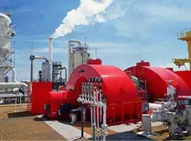
Utility-Scale Generators
At power stations, generators reach extraordinary sizes. Many occupy an entire room and are driven by enormous turbines turned by steam, water, or combustion gases. These installations depend on consistent rotational speed, tight voltage regulation, and careful coordination with the wider grid. The overall system includes boilers, condensers, cooling towers, or hydraulic works, depending on whether the plant uses fossil fuels, nuclear heat, or falling water. Although the supporting infrastructure varies, the generator itself continues to rely on the same basic electromagnetic principles. Capacity factors, fuel choices, and turbine types are covered in electricity production to illustrate real-world plant operation.
Sources of Electricity
Electricity can be generated from many different energy sources, including wind, water, solar, natural gas, biomass, and nuclear fission. The only change between these sources is the method used to generate the mechanical motion that drives the generator. Wind turbines use aerodynamic blades, hydro plants use falling water, and thermal power plants use steam generated by burning fuel or nuclear reactions. Each approach carries different engineering, economic, and environmental implications, but all converge on the same endpoint: spinning a generator to make usable electrical energy. Typical loss mechanisms and efficiency ranges across technologies are compared in electricity generation for further reading.
There are many sources of electricity, and many ways electricity can be produced and consumed. For instance, modern wind turbines are explained in electricity windmill with details on siting, capacity, and grid integration.
