Latest Electrical Engineering Articles
Load Flow Analysis - Optimizing Power
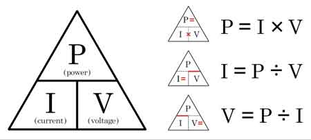
Load flow analysis evaluates the flow of voltage, current, reactive power, and active power in electrical power systems. It is essential for grid planning, stability studies, contingency analysis, and efficient energy distribution under varying load conditions.
Understanding the Role of Load Flow Analysis in Power Systems
Power System Fundamentals
Short Circuit Analysis & Protective Device Coordination
Arc Flash Analysis/Study - IEEE 1584 Update
Load flow analysis (LFA) is a crucial aspect of electrical engineering, specifically in power system planning and operation. It is a mathematical method used to determine the steady-state operating conditions of a power system network. The…
View more
Sign Up for Electricity Forum’s Electrical Engineering Newsletter
Stay informed with our FREE Electrical Engineering Newsletter — get the latest news, breakthrough technologies, and expert insights, delivered straight to your inbox.
8A and 10A Fuses in Parallel - Not Recommended
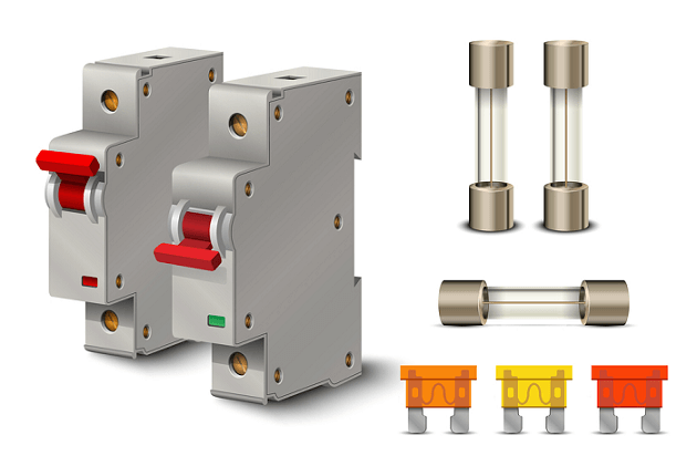
8A and 10A Fuses in Parallel can misbehave in circuit protection; unequal resistance skews load sharing and I2t. Learn wiring risks, overcurrent faults, safety implications, NEC guidance, and proper single-fuse sizing alternatives.
How 8A and 10A Fuses in Parallel Work
Connecting 8A and 10A fuses in parallel is a practice that raises many questions about safety and performance in electrical systems. While fuses are designed to protect circuits from overcurrent, mixing different ratings in parallel can lead to uneven current distribution, unreliable protection, and potential safety hazards. This article explores the implications of using fuses with different ratings, such…
View more
Short Circuit Current Calculation Explained
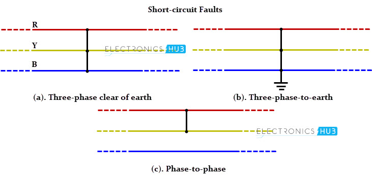
Short circuit current calculation determines the maximum electric current that can flow during a fault. It’s essential for sizing protective devices, ensuring system safety, and preventing equipment damage. Factors include voltage, impedance, transformer rating, and conductor length.
The Importance of Short-Circuit Current Calculation in Electrical Safety
This critical process enables electrical professionals to determine the magnitude of currents that can occur during fault conditions, which in turn helps them design protective measures to prevent system failures. Knowing how to perform a SCCC enables engineers and electricians to select the appropriate protective devices, minimize potential damage, and reduce downtime in…
View more
Three-Phase Bus Line Diagram Explained
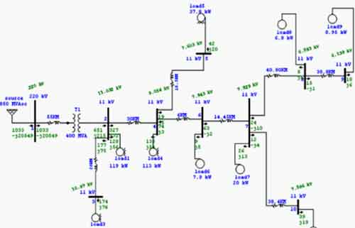
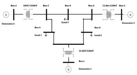
Three Phase Bus Line Diagram illustrates busbars, feeders, and switchgear in a three-phase system, using single-line schematics for substations, distribution networks, protection coordination, load flow, and fault analysis; wiring, equipment ratings, interlocks.
Three-Phase Bus Line Diagram Fundamentals
A three-phase bus line diagram is a critical tool for representing the flow of electrical power in large-scale systems such as industrial plants and power distribution grids. This type of diagram illustrates how electricity moves through a phase power system, providing a visual guide to the connections and components involved. It plays a key role in ensuring that power is distributed efficiently…
View more

Phase Rotation Meter
A phase rotation meter determines the sequence of three-phase electrical systems, ensuring correct motor connections and preventing damage to the system. It verifies phase sequence, detects wiring errors, and improves safety in industrial, commercial, and utility power applications.
Understanding the Role of the Phase Rotation Meter in Power Systems
Power System Fundamentals Training
Short Circuit Study & Protective Device Coordination Training
Arc Flash Analysis/Study Training
By understanding how to use this device, you can guarantee the safety and efficiency of your electrical installations. These systems are widely used in industrial applications because they provide a stable and efficient…
View more

How Can Mastering Electrical Training
Electrical training equips engineers and technicians with hands-on skills in power systems, circuits, NEC code compliance, PLC programming, safety procedures, instrumentation, and troubleshooting, preparing candidates for certification, apprenticeships, and advanced maintenance roles.
The Complete Guide to Electrical Training
Electrical training is the foundation for a successful career in the dynamic field of engineering. Whether you're starting your journey or looking to advance your skills, continuous learning is essential to stay ahead in this ever-evolving industry. A fundamental concept that is often explored in basic training is understanding starting current, or inrush current. Starting current refers to the surge of…
View more
DC Voltage Drop Calculation
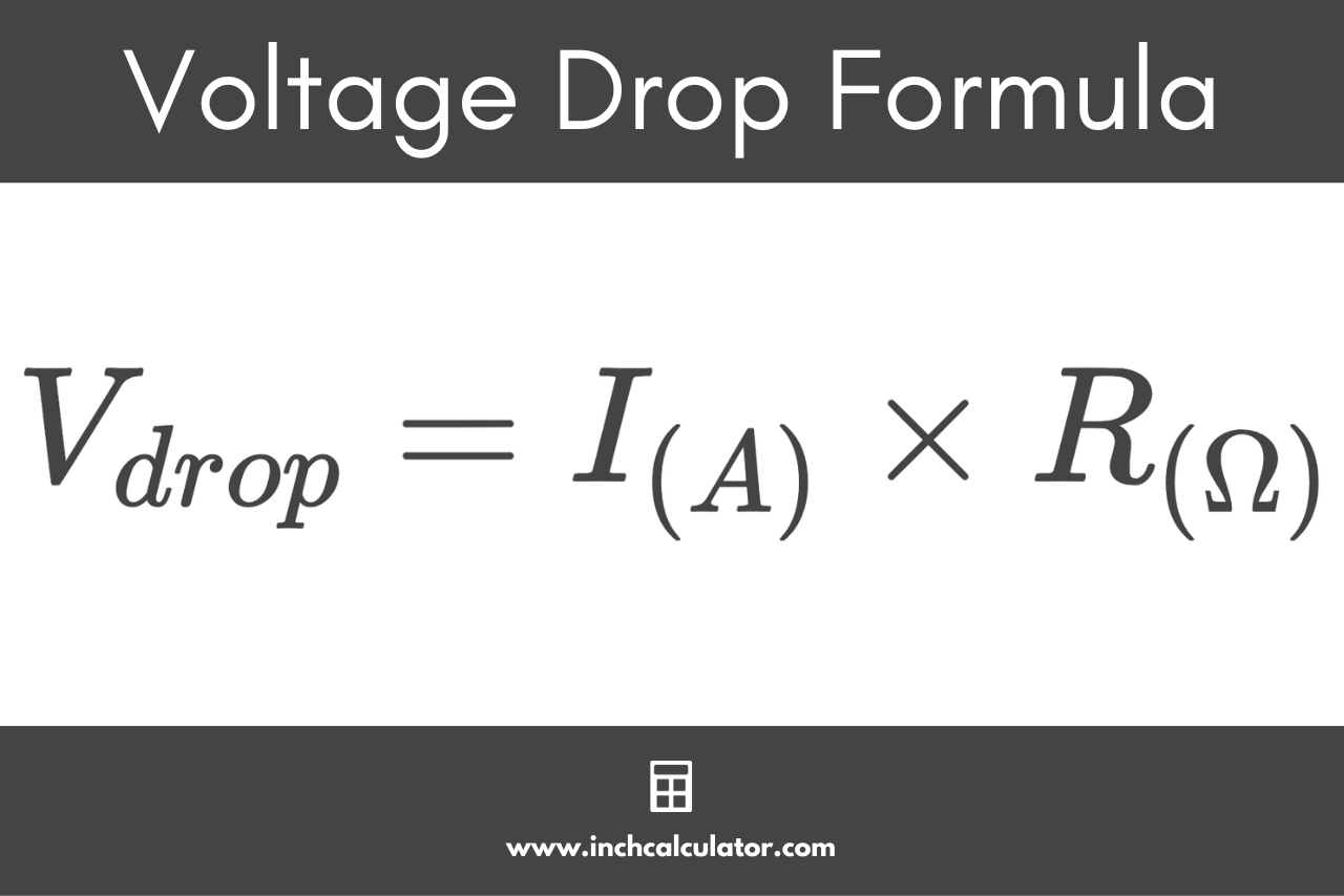
dc voltage drop calculation uses a step-by-step method to determine voltage loss in a direct current circuit using current, conductor resistance, and total circuit length to ensure proper voltage at the load in battery systems, low-voltage installations, and long cable runs.
DC voltage drop calculation applies only to direct current circuits where current flows in one direction. It is used in battery systems, DC control circuits, and low-voltage power installations. This calculation does not apply to AC systems, impedance-based conditions, or three-phase power.
The purpose of this calculation is to verify that the voltage delivered at the load remains within…
View more