Phase Rotation Meter
By William Conklin, Associate Editor
By William Conklin, Associate Editor

Our customized live online or in‑person group training can be delivered to your staff at your location.

A phase rotation meter determines the sequence of three-phase electrical systems, ensuring correct motor connections and preventing damage to the system. It verifies phase sequence, detects wiring errors, and improves safety in industrial, commercial, and utility power applications.
Power System Fundamentals Training
Short Circuit Study & Protective Device Coordination Training
Arc Flash Analysis/Study Training
By understanding how to use this device, you can guarantee the safety and efficiency of your electrical installations. These systems are widely used in industrial applications because they provide a stable and efficient power supply. The term phase rotation refers to the order in which the phases of an electrical system reach their peak values. This sequence is critical for devices like motors, as it determines the direction in which they rotate. Incorrect phase rotation can result in reverse motor operation, potentially damaging equipment and halting production. A rotational phase tester is specifically designed to detect and indicate the phase sequence, ensuring that systems are installed correctly and function safely. It is a vital tool in electrical engineering, ensuring the proper phase sequence and safe operation of motors and transformers.
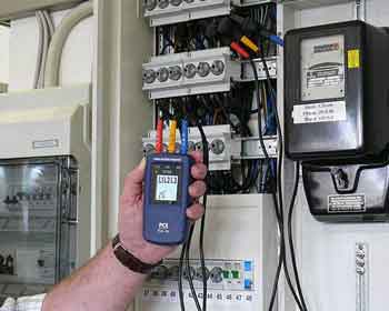
The role of this meter is straightforward yet vital. By connecting its test leads to the three conductors of a system, the device measures the sequence of the electrical phases. Many modern meters display results through intuitive interfaces, making them user-friendly even for those less experienced. The ability to verify a sequence quickly and accurately minimizes downtime during installations and troubleshooting. Understanding phase rotation is closely related to load flow analysis, which evaluates power distribution and system performance.
| Device Type | Primary Function | Advantages | Limitations |
|---|---|---|---|
| Phase Rotation Meter | Determines the three-phase sequence | Quick, accurate phase sequence detection | Limited to phase rotation checks |
| Digital Multimeter | Measures voltage, current, and resistance | Versatile, widely available | Cannot directly detect phase rotation |
| Oscilloscope | Visualizes waveforms and signal timing | Detailed phase and signal analysis | Expensive and requires technical skill |
| Clamp Meter | Measures current flow without breaking the circuit | Easy to use for current measurements | Does not indicate phase sequence |
A critical aspect of using equipment is managing the starting current or inrush current. This surge of electricity occurs when devices like motors or transformers are first activated, and it can trip circuit breakers if not properly managed. Understanding the relationship between phase sequence and starting current is essential for maintaining system stability. Properly using tools like devices helps mitigate issues caused by these initial electrical surges. Industrial electricians often use this device in conjunction with power system analysis and design to ensure optimal motor connections.
Think you know Electrical Engineering? Take our quick, interactive quiz and test your knowledge in minutes.
It is a specialized electrical testing device used to determine the direction of the rotating magnetic field in a three-phase electrical system. It identifies the sequence in which the three phases (L1, L2, L3) are arranged, which is crucial for ensuring proper motor rotation and the safe operation of equipment. Proper rotation is crucial for motors, generators, and other rotating equipment, as incorrect rotation can lead to malfunction or mechanical damage. Proper sequence verification is a key concept in power system engineering, helping prevent costly equipment failures.
From manufacturing plants to HVAC systems, the applications of testers are vast. These devices are particularly crucial when installing or maintaining machinery reliant on three-phase power, such as industrial compressors and large-scale motors. These machines could operate inefficiently or sustain permanent damage without first confirming the rotation. Additionally, they are widely used in power distribution to verify proper connections between transformers and load equipment.
It is not "calculated" in a mathematical sense but is rather "measured" or "determined" using a rotation meter or an oscilloscope. Here’s how you determine phase rotation:
Use a Meter:
Connect the three test probes of the meter to the conductors (L1, L2, L3) of the system.
Turn on the device.
The meter will display the sequence as either "ABC" (positive rotation) or "CBA" (negative rotation).
Using an Oscilloscope (Manual Method):
Connect the oscilloscope probes to the three phases.
Observe the waveform
The order in which the waveforms cross zero from negative to positive indicates the rotation.
Label the order as ABC or CBA, depending on the sequence.
A standard digital multimeter (DMM) cannot directly measure rotation, as it lacks the capability to detect the sequence. However, you can indirectly check rotation using the following method:
Identify the Phases:
Voltage Measurements:
Compare Relative Voltages:
Since a multimeter cannot detect the order of the voltages, it is recommended to use a meter for this task.
To check the sequence, follow these steps:
Turn Off Power: Ensure the system is de-energized before connecting the meter.
Connect the Meter Probes:
Turn On Power:
Check the Display:
Interpret the Results:
These steps ensure the proper functioning of motors and other equipment that rely on specific rotation for normal operation.
Electricians can enhance their skills with specialized power system training, which often includes hands-on use of rotation meters and testing tools.
Stay informed with our FREE Electrical Engineering Newsletter — get the latest news, breakthrough technologies, and expert insights, delivered straight to your inbox.
Advantages To Instructor-Led Training – Instructor-Led Course, Customized Training, Multiple Locations, Economical, CEU Credits, Course Discounts.
Request For QuotationWhether you would prefer Live Online or In-Person instruction, our electrical training courses can be tailored to meet your company's specific requirements and delivered to your employees in one location or at various locations.