Phase to Phase Connection
By William Conklin, Technical Editor
By William Conklin, Technical Editor
Our customized live online or in‑person group training can be delivered to your staff at your location.

A phase to phase connection links two live wires in a multi-phase system, delivering higher voltage than a phase to neutral setup. It's common in industrial power distribution for running heavy electrical loads efficiently.
Power System Analysis and Design Course
Arc Flash Analysis/Study Training Course
Power System Fundamentals Course
Short Circuit Analysis/Study Course
This configuration is common in industrial and commercial settings and plays a critical role in power distribution systems. Such connections offer advantages over single-line systems, particularly in handling higher loads and improving the efficiency of energy distribution. Understanding how these links work, their benefits, and the equipment that uses them is essential for anyone working in power distribution or electrical grids worldwide. To learn how phase-to-phase connections impact system behavior, see our detailed guide on load flow analysis.
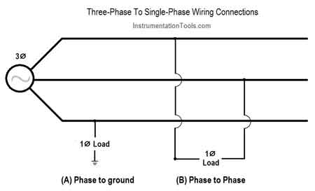
In a phase-to-phase connection, the voltage is measured between two live wires from separate power legs. This differs from a line-to-neutral setup, where voltage is measured between an energized wire and a grounded conductor. For example, in a 120-volt single-line system, the voltage between hot and neutral is 120 volts. However, in a three-wire configuration, the line-to-line voltage is typically higher. In a delta circuit, for instance, the line-to-line voltage could be 208 or 480 volts, depending on the system.
This type of connection allows for higher power transmission, making it ideal for applications like electric motors and heavy machinery.
For complete insight into design practices, visit our page on power system analysis and design.
To calculate the voltage in a phase-to-phase connection, you can use the following formula in a three-wire system:
Vline-to-line = √3 × Vline-to-neutral
This formula shows that the voltage between live wires is higher than from line to ground by a factor of √3. For example, in a typical three-conductor setup where the voltage from live to neutral is 120 volts, the line-to-line voltage would be approximately 208 volts. This calculation is crucial for determining the correct electrical potential needed for various components in a power distribution system.
Stay informed with our FREE Electrical Engineering Newsletter — get the latest news, breakthrough technologies, and expert insights, delivered straight to your inbox.
One of the main advantages of a phase-to-phase connection is its ability to deliver more power compared to a single-line setup. This makes it ideal for industrial applications where higher loads are required. In a single-wire system, energy delivery is limited, while multi-line systems can handle greater voltages and current levels, making the system more efficient and reliable.
Another advantage is that they reduce the load on individual wires. This is particularly beneficial in high-voltage transmission, where balancing loads across multiple lines minimizes stress on conductors and helps prevent overheating or failure.
You can also browse our electrical engineering channel or sign up for expert-led power system training to deepen your understanding.
While phase-to-phase connections are commonly used in industrial and commercial settings, they are not typically found in residential systems. Most homes use single-line electricity, which provides sufficient current for standard appliances and lighting. However, certain residential properties with heavy equipment, such as large HVAC units or water heaters, may include them for specific circuits. These systems are designed to handle elevated voltage levels but are generally part of specialized installations rather than the standard 120-volt residential grid.
Phase to phase connections are frequently used in equipment that requires more power than single-conductor systems can provide. Examples of such equipment include:
Electric motors in industrial machinery
High-voltage transmission lines
Heavy-duty equipment in commercial or manufacturing settings
Systems with delta wiring that distribute energy across multiple devices
These links are critical to ensuring that industrial gear operates efficiently and safely. They allow for better management of high-voltage applications, making yjr, a key element in power distribution systems across industries.
A phase to phase connection plays a vital role in modern energy infrastructure, particularly in industrial and commercial environments where higher voltages are required. Understanding how to calculate voltage between conductors and the differences between this setup and neutral-referenced circuits is essential for designing effective power systems. By utilizing them, engineers can ensure their distribution systems are robust, reliable, and capable of handling high-demand electrical loads, whether for motors or transmission lines.
Our power system engineering section explores how three-wire designs support industrial voltage requirements.
Download our FREE Electrical Training Catalog and explore a full range of expert-led electrical training courses.

Advantages To Instructor-Led Training – Instructor-Led Course, Customized Training, Multiple Locations, Economical, CEU Credits, Course Discounts.
Request For QuotationWhether you would prefer Live Online or In-Person instruction, our electrical training courses can be tailored to meet your company's specific requirements and delivered to your employees in one location or at various locations.