Short Circuit Definition

By R.W. Hurst, Editor

short circuit definition

Understanding the short circuit definition and associated risks is crucial for ensuring electrical safety in homes and workplaces. By knowing the common causes of short circuits and employing preventive measures such as regular inspections, proper installation, and protective devices like circuit breakers and GFCIs, we can minimize the dangers associated with short circuits and create a safer environment for everyone.

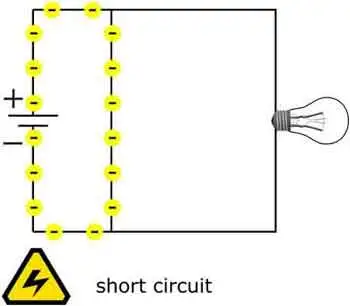
A short circuit phenomenon occurs in electrical circuits and poses potential safety hazards. To better understand the short circuit definition, one must first become familiar with the fundamentals of electrical circuits. An electrical circuit is a closed loop through which electrical current flows, and it consists of various components such as power sources, conductors, and electrical devices. A short circuit happens when an unintended, low-resistance path is formed within the circuit, causing a significant increase in current flow.


What are the different types of short circuit?

There are three main types of short circuits, each with unique characteristics and implications. These types are categorized based on the specific components of the short circuit within an electrical system. Here are the three types of short circuits:


Phase-to-Phase

This type of short circuit, also known as a line-to-line short circuit, occurs when two or more phases of an electrical system come into contact with each other. For example, this can happen when insulation between the phases is damaged or worn out, or due to a fault in the equipment or wiring. A phase-to-phase short circuit rapidly increases current flow between the affected phases, which can cause significant damage to the electrical system and generate considerable heat.


Phase-to-Neutral

A phase-to-neutral short circuit, sometimes called a line-to-neutral short circuit, occurs when a live conductor (phase) comes into contact with the neutral conductor. This can occur due to damaged insulation, loose connections, or faulty equipment. In a phase-to-neutral short circuit, the current flows between the affected phase and the neutral conductor, resulting in an increased current flow and potential damage to the electrical system.


Phase-to-Ground

This type of short circuit, also known as a ground fault, occurs when a live conductor (phase) comes into contact with a grounded object or the earth. For example, this can happen when insulation is compromised, equipment is faulty, or wiring is damaged. A phase-to-ground short circuit results in a sudden surge of current as electricity takes the path of least resistance through the ground, posing a risk of damage to electrical components, fire, and electrical shock.


Each of these types can cause significant harm to electrical systems and pose potential safety hazards. Therefore, maintaining proper insulation and connections within electrical systems and implementing protective devices such as circuit breakers and ground fault circuit interrupters (GFCIs) is crucial to minimize the risks. In addition, regular inspections and maintenance of electrical equipment are also essential in ensuring the safe operation of electrical systems.

Now that we've laid the groundwork, let's delve deeper into the definition. A short circuit is defined as an abnormal connection between two nodes in an electrical circuit, allowing an excessive amount of current to flow through a low-resistance path. This can lead to various problems, including damage to electrical components, increased risk of fire, and even electrical shock.

So, how do short circuits occur? Several common causes include damaged or frayed electrical wires, improper connections, or faulty insulation. In addition, when conductive materials come into contact, they can create an unintended path for electrical current. This leads to a significant increase in current flow, resulting in a short circuit.

The dangers associated with short circuits cannot be overstated. When a short circuit occurs, it can generate intense heat, which poses a significant fire risk. Additionally, the increased current can cause conductor failure and damage to electrical components, leading to malfunctions and even total system failure. Furthermore, if an individual comes into contact with a short-circuited component, they could suffer from electrical shock, which can sometimes be fatal.

Preventing short circuits is a vital aspect of maintaining electrical safety. One of the most effective prevention methods is ensuring proper installation and maintenance of electrical systems. In addition, regular inspections should be conducted to identify and repair damaged wiring or faulty connections. Installing overload protection devices, such as circuit breakers or fuses, can also help protect against short circuits. These devices are designed to detect and interrupt the excessive current flow, thus mitigating the risk of damage or injury.

Circuit breakers play a crucial role in safeguarding electrical systems from the effects of short circuits. These devices are engineered to detect an unusually high current flow, which could indicate a short circuit or another fault. Once detected, the circuit breaker will automatically interrupt the current flow, isolating the affected section of the circuit and preventing further damage or injury.

To further understand short circuits, it's important to distinguish them from ground faults. While both phenomena involve an abnormal connection within an electrical circuit, a ground fault is a specific type of short circuit that occurs when a live conductor comes into contact with a grounded object or the earth. This can lead to a sudden current surge and pose similar risks, such as fire and electrical shock. However, ground faults can be detected and mitigated using specialized devices called ground fault circuit interrupters (GFCIs).

Remember, always be vigilant when dealing with electrical systems. If you are uncertain about a potential issue or unsure how to handle a situation, consult a licensed electrician for assistance. Electrical safety is everyone's responsibility, and understanding definition is a fundamental step in preventing accidents and promoting a safe environment.

Related News

Understanding Current

Current is the flow of electric charge in circuits, defined by amperage, driven by voltage, limited by resistance, described by Ohm’s law, and fundamental to AC/DC power systems, loads, conductors, and electronic components.


What Is Current?

Current is charge flow in a circuit, measured in amperes and governed by voltage and resistance.

✅ Measured in amperes; sensed with ammeters and shunts

✅ Defined by Ohm’s law: I = V/R in linear resistive circuits

✅ AC alternates; DC is steady; sets power transfer P = V*I


Current is best described as a flow of charge or that the charge is moving. Electrons in motion make up an electric current. This electric current is usually referred to as “current” or “current flow,” no matter how many electrons are moving. Current is a measurement of a rate at which a charge flows through some region of space or a conductor. The moving charges are the free electrons found in conductors, such as copper, silver, aluminum, and gold. The term “free electron” describes a condition in some atoms where the outer electrons are loosely bound to their parent atom. These loosely bound electrons can be easily motivated to move in a given direction when an external source, such as a battery, is applied to the circuit. These electrons are attracted to the positive terminal of the battery, while the negative terminal is the source of the electrons. The greater amount of charge moving through the conductor in a given amount of time translates into a current. For a concise overview of how moving charges create practical circuits, see this guide to current electricity for additional context.


The System International unit for current is the Ampere (A), where


That is, 1 ampere (A) of current is equivalent to 1 coulomb (C) of charge passing through a conductor in 1 second(s). One coulomb of charge equals 6.28 billion billion electrons. The symbol used to indicate current in formulas or on schematics is the capital letter “I.” To explore the formal definition, standards, and measurement practices, consult this explanation of the ampere for deeper detail.

When current flow is one direction, it is called direct current (DC). Later in the text, we will discuss the form of current that periodically oscillates back and forth within the circuit. The present discussion will only be concerned with the use of direct current. If you are working with batteries or electronic devices, you will encounter direct current (DC) in most basic circuits.

The velocity of the charge is actually an average velocity and is called drift velocity. To understand the idea of drift velocity, think of a conductor in which the charge carriers are free electrons. These electrons are always in a state of random motion similar to that of gas molecules. When a voltage is applied across the conductor, an electromotive force creates an electric field within the conductor and a current is established. The electrons do not move in a straight direction but undergo repeated collisions with other nearby atoms. These collisions usually knock other free electrons from their atoms, and these electrons move on toward the positive end of the conductor with an average velocity called the drift velocity, which is relatively a slow speed. To understand the nearly instantaneous speed of the effect of the current, it is helpful to visualize a long tube filled with steel balls as shown in Figure 10-37. It can be seen that a ball introduced in one end of the tube, which represents the conductor, will immediately cause a ball to be emitted at the opposite end of the tube. Thus, electric current can be viewed as instantaneous, even though it is the result of a relatively slow drift of electrons. For foundational concepts that connect drift velocity with circuit behavior, review this basic electricity primer to reinforce the fundamentals.

Current is also a physical quantity that can be measured and expressed numerically in amperes. Electric current can be compared to the flow of water in a pipe. It is measureda at the rate in which a charge flows past a certain point on a circuit. Current in a circuit can be measured if the quantity of charge "Q" passing through a cross section of a wire in a time "t" (time) can be measured. The current is simply the ratio of the quantity of charge and time. Understanding current and charge flow also clarifies how circuits deliver electrical energy to perform useful work.


Electrical current is essentially an electric charge in motion. It can take either the form of a sudden discharge of static electricity, such as a lightning bolt or a spark between your finger and a ground light switch plate. More commonly, though, when we speak of current, we mean the more controlled form of electricity from generators, batteries, solar cells or fuel cells.  A helpful overview of static, current, and related phenomena is available in this summary of electricity types for quick reference.

We can think of the flow of electrons in a wire as the flow of water in a pipe, except in this case, the pipe of water is always full. If the valve on the pipe is opened at one end to let water into the pipe, one doesn't have to wait for that water to make its way all the way to the other end of the pipe. We get water out the other end almost instantaneously because the incoming water pushes the water that's already in the pipe toward the end. This is what happens in the case of electrical current in a wire. The conduction electrons are already present in the wire; we just need to start pushing electrons in one end, and they start flowing at the other end instantly. In household power systems, that push on conduction electrons alternates in direction as alternating current (AC) drives the flow with a time-varying voltage.


Current Formula

Current is rate of flow of negatively-charged particles, called electrons, through a predetermined cross-sectional area in a conductor.

 Essentially, flow of electrons in an electric circuit leads to the establishment of current.

q = relatively charged electrons (C)

t = Time

Amp = C/sec

Often measured in milliamps, mA


Related Articles

View more

Choose The Right Conductor of Electricity

Conductor of electricity describes materials with high electrical conductivity, enabling current flow via free electrons or ions under voltage, such as copper, silver, and aluminum, used in wires, busbars, grounding, and power distribution systems.


What Is a Conductor of Electricity?

A conductor of electricity is a material that easily transmits electric current via free electrons or ions.

✅ Exhibits high conductivity and low resistivity under voltage

✅ Examples: copper, silver, aluminum, graphite, saline water

✅ Enables efficient current flow in cables, busbars, and circuits


A conductor of electricity is a material that allows electric charges to flow through it with little or no resistance. Copper, aluminum, silver, gold, and nickel are some of the most common conductive materials used in electrical engineering. Conductivity is affected by several factors, such as the material's composition, temperature, and impurities. Conductors are distinguished from insulators, which are materials that do not allow electric charge to flow through them. Electrical resistance measures a material's opposition to the flow of electric current. Understanding the properties of conductive materials is essential in designing and operating electrical circuits that power our world. For foundational context, see this overview of electricity to clarify related terms.

The basic principle of a conductor is that it contains free electrons that are not bound to any particular atom. Conductors allow negatively charged electrons to flow easily in an electric field from one atom to another. When a conductor is connected to a source of electric charges, such as a battery, the electrons in the conductor begin to flow in the direction of the electric field. For newcomers, this introduction to conductors expands on how free electrons move under an applied field.

One of the most widely used conductor of electricity is copper. Copper is an excellent conductor of electrical current due to its high conductivity and low electrical resistance. As a result, copper wires are commonly used to transmit electric power over long distances. Copper is also highly durable, making it ideal for use in applications that require long-term reliability.

Aluminum is another common conductor of electrical current. It is cheaper and lighter than copper, which makes it an attractive option for electrical transmission lines. However, aluminum has a lower conductivity than copper, meaning more aluminum is needed to carry the same electric current as copper. This can lead to increased costs for larger electrical applications.

Silver is the best conductor of electrical current known to man. It has the highest electrical conductivity of any metal and is more conductive than copper. However, silver is much more expensive than copper and is only used in applications where its superior conductivity is required.

Gold is also an excellent conductor of electrical current, but it is even more expensive than silver. As a result, gold is mainly used in high-tech applications, such as electronics and aerospace, where its high conductivity and resistance to corrosion are critical.

Nickel is another metal that is a good conductor of electrical current. As a result, it is commonly used in electrical heating applications, such as in electric ovens and toasters.

A material's conductivity measures how easily it allows electric charge to flow through it. Conductivity is affected by several factors, such as the material's composition, temperature, and impurities. Pure water is an example of a poor conductor of electrical current since it contains very few free electrons.

Conductors are distinguished from insulators, which are materials that do not allow electric charge to flow through them. Rubber and plastic are good insulators that cover wires and cables to prevent electrical shock.

Electrical resistance measures a material's opposition to the flow of electric current. The resistance of a conductor depends on the material's composition, temperature, and length. In addition, Ohm's law states that the current through a conductor between two points is directly proportional to the voltage across the two points. For a deeper dive, this guide to electrical resistance explains the underlying physics and units. You can also review the resistance formula to see how voltage, current, and resistance interrelate in practice.


What are the 3 types of conductors?

Metallic conductors: Metallic conductors are materials made of metal that can conduct power. They contain free electrons not bound to any particular atom and can easily move through the metal lattice. Copper, aluminum, silver, gold, and nickel are some examples of metallic conductors.

Electrolytic conductors: Electrolytic conductors are solutions that can conduct due to the presence of dissolved ions. These solutions are typically made of an electrolyte and a solvent. Examples of electrolytic conductors include solutions of salt, acid, and base.

Semiconductor conductors: Semiconductor conductors are materials that have electrical conductivity between the conductors and insulators. They are used in electronic devices such as transistors, diodes, and solar cells. Some common semiconductor materials include silicon, germanium, and gallium arsenide.


What is the main conductor?
Copper is the most commonly used conductor due to its high electrical conductivity and low electrical resistance. It is also highly durable, making it ideal for use in applications that require long-term reliability. For example, copper wires are commonly used in power distribution systems to transmit electric power over long distances.


What properties does a conductor have?

In addition to high electrical conductivity and low electrical resistance, conductors also have high thermal conductivity, meaning they can transfer heat efficiently. In addition, they have low melting points, allowing them to be easily molded and shaped. Conductors are also ductile, easily drawn into thin wires without breaking.


What makes a good conductor of electricity?

A good conductor of electricity has a high number of free electrons available for conducting an electric charge. It also has low electrical resistance, meaning that it does not impede the flow of electric charge. In general, metals make good conductors of power because they have a high number of free electrons.


How does a conductor conduct electricity?

When a conductor is connected to a source of electric charge, such as a battery, the electric field causes free electrons in the conductor to move in the direction of the field. This movement of free electrons creates an electric current, the flow of electric charge.


What are some examples of good conductors?

Some examples of good conductors include copper, aluminum, silver, gold, and nickel. These metals have many free electrons and low electrical resistance, making them ideal for conducting an electric charge.


What is the difference between a conductor and an insulator?

The main difference between a conductor and an insulator is that a conductor allows an electric charge to flow with little or no resistance. In contrast, an insulator does not allow electric charge to flow. Insulators are typically used to cover or insulate conductors to prevent electric shock or keep the electric charge within a circuit. For a formal definition that complements this comparison, consult a concise conductor definition for precise terminology.


What is the role of a conductor in an electrical circuit?

The role of a conductor in an electrical circuit is to provide a path for the flow of electric charge. In addition, conductors connect the different components of an electrical circuit, such as resistors, capacitors, and inductors. They also transmit electric power from one place to another through power lines. For component selection context, see common types of resistors that conductors connect within practical circuits.


What is the importance of conductivity in electrical systems?

Conductivity is an essential property of materials used in electrical systems because it determines how easily an electric charge can flow through a material. Materials with high conductivity are used in applications where efficient transmission of electric power is required, such as in power distribution systems. Conversely, materials with low conductivity are used as insulators to prevent the flow of electric charge.


How does the thickness of a conductor affect its ability to conduct?

The thickness of a conductor affects its ability to conduct electrical current because thicker conductors have a lower electrical resistance. This means thicker conductors can carry more electric current with less power loss due to resistance. For example, a thin copper wire may not be able to have as much current as a thicker copper wire of the same length due to the increased resistance of the thinner wire. Therefore, the thickness of a conductor is an essential consideration in designing electrical circuits, especially for high-current applications where minimizing power loss due to resistance is critical. Additionally, thicker conductors are more durable and less likely to break under stress, making them more suitable for applications where mechanical stress is present, such as bridges and buildings.
  If these tradeoffs are new to you, this primer on electrical resistance connects cross-sectional area to current flow with clear examples.


Related Articles

View more

Resistances in Parallel

Resistances in parallel share voltage, add conductances, and reduce equivalent resistance; apply Ohm's law, current division, and circuit analysis to compute total R, branch currents, and power distribution in multi-branch networks.


What Are Resistances in Parallel?

Parallel resistors share voltage; total resistance decreases by summing conductances (1/R).

✅ Equivalent 1/Rt = sum(1/Ri); lower than smallest branch

✅ Same voltage across branches; currents split by conductance

✅ Use Ohm's law and current division to size components, power


Resistances in parallel is a common term used in industrial, commercial, and institutional power systems. Therefore, a good understanding of working with resistors in parallel and calculating their various parameters is crucial for maintaining safe and efficient operations. For foundational context, see this overview of electrical resistance for key definitions applied throughout.

It means that when resistors are connected in parallel, they share the same voltage across them. Hence, this means that the resistances are in parallel. This is because the total resistance of the resistors in parallel is less than that of any individual resistor, making it a useful configuration for reducing resistance and increasing current in a circuit. A clear grasp of electrical resistance helps explain why parallel branches draw more current.

Adding more resistors in parallel reduces the circuit's total resistance, increasing the current. However, adding too many resistors in parallel can overload the circuit and cause it to fail. Engineers often verify safe loading using the resistance formula to predict current increases.


Understanding Resistances in Parallel

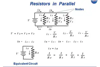
They refer to the configuration in which two or more resistors are connected side by side across the same voltage points in an electrical circuit. In this arrangement, the voltage across each resistor is the same, while the current is divided among the resistors according to their resistance values. This configuration is commonly used in circuit analysis to simplify complex circuits and determine the equivalent parallel resistance.

When simplifying networks, computing the equivalent resistance streamlines analysis and component selection.


Calculating the Equivalent Resistance

To calculate the equivalent resistance of resistances in parallel, the reciprocal of the equivalent resistance (1/Req) is equal to the sum of the reciprocals of the individual resistances (1/R1 + 1/R2 + ... + 1/Rn). This formula is crucial in resistance calculation and helps engineers design efficient power systems that meet the desired voltage drop and current distribution requirements. A comparable reciprocal relationship appears when evaluating capacitance in series under similar analysis methods.

To calculate the total resistance of resistors in parallel, the reciprocal of each resistor is added together, and then the result is inverted to give the total resistance. This can be represented mathematically as:

1/Rt = 1/R1 + 1/R2 + 1/R3 + ...

where Rt is the total resistance and R1, R2, R3, etc. are the individual resistors.


Five resistors R(1) through R(5), connected in parallel, produce a net resistance R.


In a circuit with resistors in parallel, the current is divided among the resistors according to their individual resistance values. This is known as the current division, and it can be calculated using Ohm's law and the circuit's total resistance. The formula for calculating the current through each resistor in parallel is:

I1 = (V/R1) * (R2/(R2 + R3)) I2 = (V/R2) * (R1/(R1 + R3)) I3 = (V/R3) * (R1/(R1 + R2))

where I1, I2, and I3 are the currents through each resistor, V is the voltage across the circuit, and R1, R2, and R3 are the individual resistors.

Simplifying a circuit with resistors in parallel involves finding the equivalent resistance of the circuit. This is the resistance value that would produce the same current as the original parallel circuit, and it can be calculated using the reciprocal formula:

1/Req = 1/R1 + 1/R2 + 1/R3 + ...

where Req is the equivalent resistance.


Impact on Total Resistance

In a parallel configuration, adding more resistors decreases the total resistance. The reason is that the current has multiple paths to flow through, reducing the overall opposition to current flow. This characteristic is particularly useful in designing power supply systems, where lower resistance is desired to minimize energy losses and improve system efficiency. By contrast, capacitance in parallel increases as components are added, offering a helpful design analogy.


Practical Applications

They are employed in various real-life circuits and power systems. For instance, they are commonly found in circuit simulations, power distribution systems, and load balancing applications. In industrial settings, a parallel resistor calculator is often used to measure multiple current paths for fault protection and redundancy. In commercial and institutional power systems, parallel configurations are employed to manage load distribution and ensure system reliability.


Differences between Parallel and Series Connections

In a series circuit, resistors are connected end-to-end, and the current flows consecutively from the source of each resistor. The total resistance in a series circuit equals the sum of individual resistances, and the voltage drop across each single resistor is different. In contrast, they share the same voltage, and the total resistance decreases as more resistors are added. Identifying these connections in a circuit diagram is crucial for proper circuit analysis and design. For direct comparison of methods, review resistance in series to see how sums differ from reciprocals.


Combining Resistances in Parallel and Series

They can be combined with resistances in series within the same circuit. In such cases, equivalent resistances for both parallel and series sections are calculated separately. Then, the total resistance is determined by adding the equivalent resistances of the series and parallel sections. This approach helps engineers analyze complex circuits and design efficient power systems.

They are crucial to industrial, commercial, and institutional power systems. Understanding how to calculate the total resistance, current distribution, and power dissipation of resistors in parallel is essential for maintaining safe and efficient operations. In addition, engineers can optimize their designs for optimal performance by using circuit simulation software and other tools.


Related Articles

View more

Resistance in Series Explained

Resistance in series refers to the arrangement of individual resistors in a circuit, where the current flows through each resistor end to end. In this configuration, the total resistance (R) of the circuit is equal to the sum of the individual resistances, also known as the equivalent R.


What is Resistance in Series?

Resistance in series refers to a circuit configuration where resistors are arranged in a single path:

✅ Total resistance is the sum of all resistors in the circuit

✅ The same current flows through each resistor

✅ Voltage divides across each resistor based on its value

To calculate the total R in a series circuit, the individual resistances of each resistor are added together. The formula to calculate the equivalent resistance in a series connection is Rtotal = R1 + R2 + R3 + ..., where R1, R2, R3, and so on, represent the individual resistances of each resistor in the circuit.

Ohm's law also applies to series circuits, where the current through each resistor is the same, but the voltage across each resistor is proportional to its R. The total voltage across the series combination of resistors equals the sum of the voltage drops across each resistor.

It is essential to note that the total resistance in a series circuit is always greater than the resistance of any individual resistor in the circuit, due to the cumulative effect of each resistor's resistance.

On the other hand, resistors connected in parallel result in a parallel circuit. The equivalent R of a parallel circuit is calculated differently from a series connection. Instead of adding the individual resistances, the reciprocal of each R is added, and the resulting value is inverted to obtain the equivalent resistance.


R in Series - Parallel

When you place R-I-S, their ohmic values add up arithmetically to reach the total (or net) R.

We can connect a series of resistors (equal to the sum of the individual resistances of a parallel circuit), all having identical ohmic values, in parallel sets of series networks or series sets of parallel networks. When we do either of these things, we create a series-parallel network that can significantly increase the total power-handling capacity of the network compared to the power-handling capacity of a single parallel resistor.


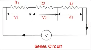
Fig. 4-14. Three resistors in series. 

Sometimes, the total single equivalent R of the combination circuit in a series-parallel network equals the value of any one of the resistors. This always happens if the parallel branches or parallel combinations of the connection components are all identical and are arranged in a network called an n-by-n (or n x n) matrix. That means when n is a whole number, we have n series sets of n resistors connected in parallel, or else we have n parallel sets of n resistors connected in series in the circuit. These two arrangements yield the same practical result for electrical circuits.

A combination of series parallel combinations array of n by n resistors, all having identical ohmic values and identical power ratings, will have n2 times the power-handling capability of any resistor by itself. For example, a 3 x 3 series-parallel matrix of 2 W resistors can handle up to 32 x 2 = 9 x 2 = 18 W. If we have a 10 x 10 array of 1/2 W resistors, then it can dissipate up to 102 x 1/2 = 50 W. We multiply the power-handling capacity of each individual resistor by the total number of resistors in the matrix.

The above-described scheme works if, but only if, all of the resistors have identical ohmic values according to ohms law and identical power-dissipation ratings in terms of total voltage drops when the sum of the voltage drops across each resistor. If the resistors have values that differ even a little bit from one another, one of the components will likely draw more current than it can withstand, so that it will burn out, no matter the voltage source. Then the current distribution in the network will change further, increasing the likelihood that a second resistor will fail, and maybe more.

If you need a resistor that can handle 50 W, and a certain series-parallel connection of the network will handle 75 W, that's fine. But you should not "push your luck" and expect to get away with using a network that will handle only 48 W in the same application. You should allow some extra tolerance, say 10 per cent over the minimum rating. If you expect the network to dissipate 50W, you should build it to handle 55W or a bit more. You don't have to use "overkill," however. You'll waste resources if you cobble together a network that can handle 500W when you only expect it to cope with 50W—unless that's the only convenient combination you can make with available resistors.


Related Articles


View more

Electrical Units Explained

Electrical units measure various aspects of electricity, such as voltage (volts), current (amperes), resistance (ohms), and power (watts). These standard units are crucial in electrical engineering, circuit design, energy monitoring, and ensuring the safe operation of electrical systems.


What are Electrical Units?

Electrical units are standardized measures used to quantify electrical properties in circuits and systems.

✅ Measure voltage, current, resistance, power, and energy

✅ Used in electrical engineering, testing, and design

✅ Support safe and efficient electrical system operations

Electrical units are standardized measurements that describe various aspects of electricity, such as current, voltage, resistance, and power. These units, like amperes for current and volts for voltage, help quantify the behavior and interaction of systems. By understanding electrical units, professionals can assess performance, design circuits, and ensure safety across different applications. These electrical units play a crucial role in the functioning of everything from household appliances to industrial machinery, making them fundamental in engineering and everyday technology.

In common electricity systems, various electrical units of measure, such as magnetic field, are used to describe how electricity flows in the circuit. For example, the unit of resistance is the ohm, while the unit of time is the second. These measurements, often based on SI units, help define the phase angle, which describes the phase difference between current and voltage in AC circuits. Understanding these electrical units is critical for accurately analyzing performance in both residential and industrial applications, ensuring proper function and safety.


Ampere

The ampere is the unit of electric current in the SI, used by both scientists and technologists. Since 1948, the ampere has been defined as the constant current that, if maintained in two straight, parallel conductors of infinite length and negligible circular cross-section, and placed one meter apart in a vacuum, would produce between these conductors a force equal to 2 × 10^7 newtons per meter of length. Named for the 19th-century French physicist André-Marie Ampere, it represents a flow of one coulomb of electricity per second. A flow of one ampere is produced in a resistance of one ohm by a potential difference of one volt. The ampere is the standard unit of electric current, playing a central role in the flow of electricity through electrical circuits.


Coulomb

The coulomb is the unit of electric charge in the metre-kilogram—second-ampere system, the basis of the SI system of physical electrical units. The coulomb is defined as the quantity of electricity transported in one second by a current of one ampere. Named for the I8th—I9th-century French physicist.


Electron Volt

A unit of energy commonly used in atomic and nuclear physics, the electron volt is equal to the energy gained by an electron (a charged particle carrying one unit of electronic charge when the potential at the electron increases by one volt. The electron volt equals 1.602 x IO2 erg. The abbreviation MeV indicates 10 to the 6th (1,000,000) electron volts, and GeV, 10 to the 9th (1,000,000,000). For those managing voltage drop in long circuits, we provide a helpful voltage drop calculator and related formulas to ensure system efficiency.


Faraday

The Faraday (also known as the Faraday constant) is used in the study of electrochemical reactions and represents the amount of electric charge that liberates one gram equivalent of any ion from an electrolytic solution. It was named in honour of the 19th-century English scientist Michael Faraday and equals 6.02214179 × 10^23 coulombs, or 1.60217662 × 10^-19 electrons.


Henry

The henry is a unit of either self-inductance or mutual inductance, abbreviated h (or hy), and named for the American physicist Joseph Henry. One henry is the value of self-inductance in a closed circuit or coil in which one volt is produced by a variation of the inducing current of one ampere per second. One henry is also the value of the mutual inductance of two coils arranged such that an electromotive force of one volt is induced in one if the current in the other is changing at a rate of one ampere per second.


Ohm

The unit of resistance in the metre-kilogram-second system is the ohm, named in honour of the 19th-century German physicist Georg Simon Ohm. It is equal to the resistance of a circuit in which a potential difference of one volt produces a current of one ampere (1 ohm = 1 V/A); or, the resistance in which one watt of power is dissipated when one ampere flows through it. Ohm's law states that resistance equals the ratio of the potential difference to current, and the ohm, volt, and ampere are the respective fundamental electrical units used universally for expressing quantities. Impedance, the apparent resistance to an alternating current, and reactance, the part of impedance resulting from capacitance or inductance, are circuit characteristics that are measured in ohms. The acoustic ohm and the mechanical ohm are analogous units sometimes used in the study of acoustic and mechanical systems, respectively. Resistance, measured in ohms, determines how much a circuit resists current, as explained in our page on Ohm’s Law.


Siemens

The siemens (S) is the unit of conductance. In the case of direct current (DC), the conductance in siemens is the reciprocal of the resistance in ohms (S = amperes per volt); in the case of alternating current (AC), it is the reciprocal of the impedance in ohms. A former term for the reciprocal of the ohm is the mho (ohm spelled backward). It is disputed whether Siemens was named after the German-born engineer-inventor Sir William Siemens(1823-83) or his brother, the engineer Werner von Siemens (1816-92).


Volt

The unit of electrical potential, potential difference, and electromotive force in the metre—kilogram—second system (SI) is the volt; it is equal to the difference in potential between two points in a conductor carrying one ampere of current when the power dissipated between the points is one watt. An equivalent is the potential difference across a resistance of one ohm when one ampere of current flows through it. The volt is named in honour of the I8th—I9th-century Italian physicist Alessandro Volta. Ohm's law defines these electrical units, where resistance equals the ratio of potential to current, and the respective units of ohm, volt, and ampere are used universally for expressing electrical quantities. Energy consumption is measured in kWh, or kilowatt-hours. Explore how devices like ammeters and voltmeters are used to measure current and voltage across components. To better understand how voltage is measured and expressed in volts, see our guide on what is voltage.


Watt

The watt is the unit of power in the SI equal to one joule of work performed per second, or to 1/746 horsepower. An equivalent is the power dissipated in a conductor carrying one ampere of current between points at a one-volt potential difference. It is named in honour of James Watt, British engineer and inventor. One thousand watts equals one kilowatt. Most electrical devices are rated in watts. Learn how a watt defines power in electrical systems and its relationship to volts and amperes through Watts' Law.


Weber

The weber is the unit of magnetic flux in the SI, defined as the amount of flux that, linking a circuit of one turn (one loop of wire), produces in it an electromotive force of one volt as the flux is reduced to zero at a uniform rate in one second. It was named in honour of the 19th-century German physicist Wilhelm Eduard Weber and equals 10 to the 8th maxwells, the unit used in the centimetre—gram—second system.

Related Articles


View more

Unit of Electrical Resistance - Understanding the Ohm

The unit of electrical resistance is the ohm, symbolized by the Greek letter Ω. It measures how much a material resists the flow of electric current. One ohm equals the resistance when one volt produces a current of one ampere.


What is a unit of electrical resistance?

The unit of electrical resistance, the Ohm, is a cornerstone of the electrical world. Its importance in governing the behaviour of electric currents, designing efficient circuits, and ensuring the safe operation of devices cannot be overstated. By understanding the intricacies of resistance and Ohm's law, it is possible to harness the power of electricity to create innovative and practical solutions that benefit our daily lives.


Here’s what you need to know:

✅ Ohm (Ω) is the standard unit of electrical resistance in the International System of Units (SI).
✅ One ohm equals the resistance that allows one ampere of current to flow with a voltage of one volt.
✅ Resistance determines how easily electricity can flow through a conductor or component.

The world of electricity is complex and fascinating, with numerous components working in unison to power our lives. One such essential element is the unit of electrical resistance, the Ohm (Ω), named after Georg Simon Ohm, a German physicist. The Ohm plays a vital role in the functioning of electrical circuits and everyday devices. This article delves into the intricacies of this unit and its significance in the realm of electricity.

First and foremost, it is crucial to understand the basic concept of resistance. In simple terms, resistance is the opposition to the flow of electric current through a conductor. It is an essential factor that influences the behaviour and efficiency of electrical circuits. The Ohm (Ω) is the SI unit of electric resistance, represented by the Greek letter omega (Ω). One Ohm is defined as the resistance of a conductor that allows one ampere of current to flow when one volt of potential difference is applied across it.

Ohm's law defines the relationship between resistance, voltage, and electric current, a fundamental principle in electrical engineering. The law states that the current passing through a conductor is directly proportional to the voltage applied and inversely proportional to its resistance. Mathematically, it is expressed as V = IR, where V represents the voltage, I represents the electric current, and R represents the resistance. This equation helps in determining the resistance in various circuits and devices.

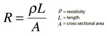
Several factors influence the resistance of a material, including its resistivity, length, cross-sectional area, and temperature. For example, materials with high resistivity, such as insulators, exhibit greater resistance than conductors, which have low resistivity. Additionally, longer conductors and those with smaller cross-sectional areas have higher resistance compared to shorter conductors and those with larger cross-sectional areas. The temperature of a material also affects its resistance, as resistance typically increases with a rise in temperature.


How do I measure electrical resistance?

You can use a multimeter, a versatile electronic measuring instrument, to measure the resistance of a component or a circuit. A multimeter can measure various electrical parameters, including voltage, current, and resistance. Follow these steps to measure the resistance of a component or circuit:

  1. Turn off the power

  2. Choose the right setting

  3. Prepare the component or circuit

  4. Connect the probes

  5. Read the resistance

Interpret the results by comparing the measured resistance with the expected or specified value for the component or circuit. If there is a significant deviation, the component might be damaged, or the circuit may have a fault.

Factors such as temperature and contact resistance between the probes and the component can affect the readings when measuring resistance. Therefore, it's essential to consider these factors when interpreting the measurement results.


Resistance

Resistance plays a critical role in electrical circuits, as it regulates the flow of current and maintains the proper functioning of devices. Limiting the current flow ensures that electrical components do not overheat or become overloaded. Resistors are passive electronic components specifically designed to provide a precise amount of resistance in a circuit.

Impedance, another essential concept in electricity, is closely related to resistance. While resistance refers to the opposition of a direct current (DC), impedance encompasses both resistance and capacitance, the latter being the opposition to alternating current (AC) due to capacitive or inductive effects. Essentially, impedance is the total opposition to the flow of alternating current, combining both resistance and reactance.

The applications are vast and varied, encompassing everyday life and advanced technology. For example, resistance is integral to household appliances like electric heaters, toasters, and incandescent light bulbs, which help generate heat or light. It also plays a significant role in the design of electronic circuits and complex systems, such as computer processors.


Related Pages


View more

Sign Up for Electricity Forum’s Newsletter

Stay informed with our FREE Newsletter — get the latest news, breakthrough technologies, and expert insights, delivered straight to your inbox.

Electricity Today T&D Magazine Subscribe for FREE

Stay informed with the latest T&D policies and technologies.
  • Timely insights from industry experts
  • Practical solutions T&D engineers
  • Free access to every issue

Live Online & In-person Group Training

Advantages To Instructor-Led Training – Instructor-Led Course, Customized Training, Multiple Locations, Economical, CEU Credits, Course Discounts.

Request For Quotation

Whether you would prefer Live Online or In-Person instruction, our electrical training courses can be tailored to meet your company's specific requirements and delivered to your employees in one location or at various locations.