Wattmeters – Power Measurement
By Colin P. Hurst, Associate Publisher
Wattmeters measure electrical power in watts, monitoring energy use in industrial power systems. They provide accurate active power readings for efficiency and load management, utilizing voltage and current measurements to achieve precise results.
Applications of Wattmeters in Modern Power Systems
A wattmeter measures instantaneous (or short-term) electrical power in watts, while a watthour meter accumulates that power over time and reports energy used (e.g. in kWh). Energy meters and smart meters extend this concept by recording consumption continuously for billing, load analysis, and energy audits.
Working Principle of Wattmeters
Electrical power is calculated using the formula:
P = E × I
Where:
-
P = Power in watts
-
E = Voltage in volts
-
I = Current in amperes
In DC circuits, watts are sometimes expressed as volt-amperes (VA). In AC circuits, wattmeters measure true (or active) power, taking into account the power factor to compensate for phase differences between voltage and current. Unlike reactive power (measured in kvar) or apparent power (measured in kVA), active power is the usable portion that does real work. This relationship is often represented in the power triangle, where vector analysis explains how apparent, reactive, and active power interact.
Construction and Internal Components
A typical wattmeter consists of two main coil assemblies:
-
Current Coil (CC)
-
Heavy-gauge copper wire with low resistance.
-
Connected in series with the load to carry the circuit current.
-
-
Voltage Coil (VC)
-
Fine-gauge wire with high resistance.
-
Connected in parallel with the load to measure voltage.
-
The electrodynamometer, commonly referred to as a dynamometer wattmeter, is a classic analog device that operates on the principle of a motor. The interaction between the magnetic fields of the current and voltage coils produces a torque proportional to the power, causing the pointer to move over a calibrated scale. Understanding wattmeter principles is a foundation of basic electricity training, helping learners connect theory to practical power measurement.
Figure 1 – Construction of a dynamometer wattmeter showing current and voltage coil arrangement.
Types of Wattmeters
-
Analog/Dynamometer – Durable, reliable, suited for laboratory and field measurements.
-
Digital – Higher accuracy, data logging, and integration with monitoring systems.
-
Clamp-on – Measure power without breaking the circuit, ideal for quick diagnostics.
-
Specialized – Designed for RF power, audio power, or other niche applications.
In three-phase systems, wattmeters are often applied in accordance with Blondel’s theorem, which specifies the number of measurement elements required in multi-phase circuits. They are frequently used in conjunction with 3 phase electricity concepts to ensure balanced load distribution and optimal system efficiency.
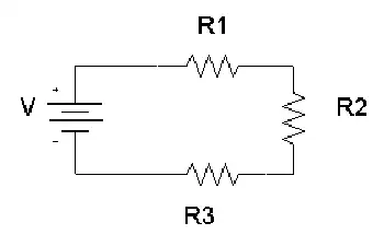
Fig. 2. Power can be measured with a voltmeter and an ammeter.
Measuring Power in DC and AC Circuits
In DC circuits, power measurement can be as simple as multiplying voltage and current readings from separate meters.
Example:
If a circuit operates at 117 V DC and draws 1 A, the power is:
P = 117 × 1 = 117 W
In AC systems, especially with reactive or distorted loads, a wattmeter is essential because voltage and current may not be in phase. The device automatically accounts for the phase angle, providing accurate true power readings. Advanced digital wattmeters also compensate for harmonic distortion and poor waveform quality, providing more reliable measurements than older analog designs.
By measuring energy transfer in circuits, they also relate to other power measurement instruments such as ammeters, voltmeters, and multimeters, which measure supporting parameters needed for complete electrical analysis. Accurate wattmeter readings are crucial for diagnosing performance issues in 3-phase power networks, where the relationships between voltage and current are critical. By measuring energy transfer in circuits, they help explain fundamental laws of electromagnetism, such as Ampère’s Law, which underpins the interaction between current and magnetic fields.
Fig. 2. Power can be measured with a voltmeter and an ammeter.
Practical Examples and Load Considerations
A household iron may consume 1000 W, drawing 8.55 A at 117 V.
A large heater may draw 2000 W, or 17.1 A, potentially overloading a 15 A breaker.
In industrial settings, watt meters help prevent equipment overloading, reduce downtime, and improve energy efficiency.
Modern Wattmeter Applications
Today’s wattmeters are often part of smart energy monitoring systems that:
-
Track energy consumption over time.
-
Integrate with SCADA and IoT platforms.
-
Enable predictive maintenance through power trend analysis.
-
Support compliance with energy efficiency regulations.
Accuracy, Standards, and Advanced Considerations
Measurement accuracy is a crucial factor in determining wattmeter performance. Devices are often classified by a class of accuracy, with error limits defined by international standards such as IEC, ANSI, or IEEE. Regular calibration and testing procedures ensure watt meters continue to deliver reliable results in both laboratory and field conditions.
Modern digital watt meters feature true RMS measurement, which accurately captures distorted waveforms caused by nonlinear loads. This is especially important in power systems where harmonic distortion is present. In commercial and industrial environments, accurate wattmeter data support energy audits, load analysis, and regulatory compliance, making them indispensable tools for engineers and facility managers. Wattmeter usage is closely linked to the fundamentals of electrical energy, enabling precise monitoring for efficiency and cost control.
Key Advantages of Wattmeters
-
Accurate real-time power measurement.
-
Enhanced energy management and cost savings.
-
Improved system reliability through overload prevention.
-
Compatibility with both AC and DC systems.
Wattmeters remain a vital tool for measuring and managing electrical power. Whether in a simple residential circuit, a commercial energy audit, or a high-tech industrial monitoring system, they ensure that electrical systems run efficiently, safely, and cost-effectively. As technology advances, digital and networked wattmeters continue to expand their role, integrating into smart grids and energy-optimized infrastructures.