Electricity Supply And Demand Balance


Electricity Supply

Electricity supply covers generation, transmission, distribution, grid infrastructure, voltage regulation, frequency control, power quality, protection, SCADA, and load management to ensure reliable energy delivery to industrial, commercial, and residential loads.


What Is Electricity Supply?

Electricity supply is generation, transmission and distribution of power with set voltage, frequency and reliability.

✅ Involves generation, HV transmission, MV/LV distribution networks

✅ Ensures voltage regulation, frequency control, and power quality

✅ Uses SCADA, protection relays, and load forecasting for reliability


What Is Electricity Supply?

Electricity Supply is a complex balanced system of electric power generation and real time customer demand. Production (supply) and consumption (demand) dictate electricity pricing in the United States and Canada.  For a regional view, the analysis at Electricity Demand in Canada highlights how seasonal peaks and resource availability shape prices.

Where does the term "electricity supply" originate? How does that supply move from one point to another? These are most important questions to ask when you want to understand the electric power industry.

If you're new to the vocabulary, the concise glossary at Electricity Terms can clarify definitions used throughout the industry.

The first thing to know is that electric power is generated in the United States and Canada in power plants which house electrical generators. Then, power is transported (transmission and distriubtution) through the power grid to the customer. This complex network of transmission lines delivers power to industrial, commercial, institutional and residential customers. For a step-by-step overview of system operations, Electricity: How It Works explains generation, transmission, and distribution in practical detail.

In the electricity industry, transmission and distribution wires do the work of transporting power to satisfy electricity demand during real time peak demand. This is the job of the electricity market. The natural gas and fossil fuels industry works in the same way. These lines run from generating station to substations (sometimes over great distances, like in the case of British Columbia and Manitoba where generation is in the far north and the consumption is in the south. This is where the voltage is reduced for local consumption. Substations are usually located close to where the electricity is consumed. 

For background on core power concepts, the primer at Electricity Power connects voltage, current, and load to real-world grid behavior.

The various prices of electricity depends on the electricity supply mix and the energy efficiency of the customer. Electricity energy supply is usually measured in terawatt hours.

The system design is of three-phase alternating current electrical generation and distribution, which was invented by Nikola Tesla in the 19th century. He considered that 60 Hz was the best frequency for alternating current (AC) power generating Electricity Supply. He preferred 240 V, which was claimed to be better for long supply lines. Thomas Edison developed direct current (DC) systems at 110 V and this was claimed to be safer. For more information about the early battles between proponents of AC and DC supply systems see War of Currents. For foundational fundamentals beyond this history, the overview at What Is Electricity clarifies the principles common to both AC and DC systems.

The German company AEG built the first European generating facility to run at 50 Hz, allegedly because the number 60 did not fit into the numerical unit sequence of 1, 2, 5…. At that time, AEG had a virtual monopoly and their standard spread to the rest of the continent. In Britain, differing frequencies (including 25 Hz 40 Hz and DC) proliferated, and the 50 Hz standard was established only after World War II.

To see how frequency standards interact with generation and end-use performance, the explainer at How Electricity Works ties design choices to everyday operation.

Originally much of Europe was 110 V too, just like the Japanese and the US system today. It was deemed necessary to increase the necessary voltage to draw more electrical power with reduced energy loss and voltage drop from the same copper wire diameter.

The choice of utilization voltage is governed more by tradition than by optimization of the distribution system. In theory, a 240 V distribution system will use less conductor material to deliver a given quantity of power. Incandescent lamps for 120 V systems are more efficient and rugged than 240 V lamps, while large heating appliances can use smaller conductors at 240 V for the same output rating. Practically speaking, few household appliances use anything like the full capacity of the outlet to which they are connected. Minimum wire sizes for hand-held or portable equipment is usually restricted by the mechanical strength of the conductors. One may observe that both 240 V system countries and 120 V system countries have extensive penetration of electrical appliances in homes. National electrical codes prescribe wiring methods intended to minimize the risk of electric shock or fire. For household applications, home electricity basics show how these voltage considerations affect outlets, circuits, and safety practices.

Areas using (approximately) 120V allow different combinations of voltage, suitable for use by a variety of classes of electrical equipment.


Related Articles

Related News

Electricity Generator

Electricity generator converts mechanical energy to electrical power via electromagnetic induction using a prime mover, alternator, stator, and rotor, delivering regulated AC/DC output, high efficiency, and stable voltage and frequency.


What Is an Electricity Generator?

An electricity generator converts mechanical energy to electric power using electromagnetic induction, AC or DC.

✅ Converts rotational torque into regulated AC or DC output

✅ Uses stator, rotor, and excitation for voltage regulation

✅ Applied in power plants, gensets, microgrids, and renewables


An Electricity Generator can create electricity by converting mechanical energy into electrical current that can be used in electrical systems. Wind turbines house such generators to convert the kinetic energy of wind into power that can feed power grids. involve the production of electrons that are a part of every atom,. Electricity is what results when electrons are flowing through a conductor. Ultimately, all that is needed to generate electricity is a metal wire for a conductor and a catalyst to start the electrically charged electrons flowing. You see, unlike natural gas and other fossil fuels that are mined from the Earth, electricity is a manufactured product. Most generators operated by electric utilties are alternating current (ac) generators but there are still some direct current (dc) generators in existence. For a clear primer on charge, current, and how generators relate to these basics, see what is electricity to ground these concepts.

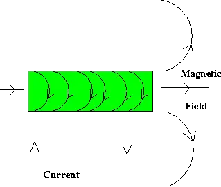
Alternating current is easily generated by means of a rotating magnet windings in a coil of wire, or by a rotating coil of wire inside a powerful magnet. In either case, the ac appears between the ends of the length of wire. This takes place in an electricity generator, which was invented by Michael Faraday. A portable generator can be used as backup power during a power outage. If you want a step-by-step view of induction and circuit behavior, consult how electricity works for context beyond this overview.

The ac voltage that a generator (motor) can develop depends on the strength of the magnets field, the number of turns in the wire coil, and the speed at which the magnet or coil rotates. The ac frequency depends only on the speed of rotation. Normally, for utility ac, this speed is 3,600 revolutions per minute (rpm), or 60 complete revolutions per second (rps), so that the frequency is 60 Hz. Design choices that set coil turns, flux, and rotational speed are discussed in how electricity is generated with practical examples.

When a load, such as a light bulb or heater, is connected to an ac generator, it becomes more difficult to turn the generator. The more power needed from a generator, the greater the amount of power required to drive it. This is why it is not possible to connect a generator to, for instance, your stationary bicycle, and pedal an entire city into electrification. There's no way to get something for nothing. The electrical power that comes out of a generator can never be more than the mechanical power driving it. In fact, there is always some energy lost, mainly as heat in the generator. Your legs might generate 50 W of power to run a small radio, but nowhere near enough to provide electricity for a household. Realistic scenarios for human power and small prime movers are outlined in generate electricity to help size expectations.

The efficiency of a generator is the ratio of the magnet generate power output to the driving power, both measured in the same units (such as watts or kilowatts), multiplied by 100 to get a percentage. No generator is 100 percent efficient. But a good one can come fairly close to this ideal. Typical loss mechanisms and efficiency ranges across technologies are compared in electricity generation for further reading.

At power plants, the power generators can be huge. Each one can be as big as a house. In a power plant, each electricity generator is driven by a massive turbine. Often, steam drives the turbine, and the steam is obtained via heat derived from natural energy source, like falling water. Capacity factors, fuel choices, and turbine types are covered in electricity production to illustrate real-world plant operation.

There are many different sources of electricity and many different ways electricity can be produced and consumed. For instance, modern wind turbines are explained in electricity windmill with details on siting, capacity, and grid integration.


Related Articles

View more

Hydroelectricity Explained

Hydroelectricity converts hydropower into grid-ready electricity using dams, penstocks, turbines, and generators, enabling renewable baseload, pumped storage, high efficiency, and low emissions for resilient power systems with load balancing, frequency regulation, and strong capacity factors.


What Is Hydroelectricity?

Hydroelectricity is electricity generated by water turning turbines at dams, delivering low-carbon power to the grid.

✅ Converts hydraulic head and flow into alternating current.

✅ Uses synchronous generators, excitation, and step-up transformers.

✅ Supports grid inertia, regulation, and pumped-storage balancing.


Hydroelectricity is another term for power generated by harnessing the power of damming rivers and moving water into generating plants. Not necessarily falling water, just moving water. There are many famous such Hydroelectricity stations in the world, not the least of them at Niagara Falls, Grand Coulee and Boulder Dam and the three gorges dam in China . In the past, small plants produced electric hydroelectricity. Now, they are massive in size and generation capcity as well as having large reservoirs. If there is a need for power electrical generation stations situated close to the point of consumption is ideal. These are just a few of the many examples of energy produced by falling water. On the other hand, a small mill set in the rapids of a fast-moving stream is also an example of it in action, on a lesser scale. The truth is that any steady current of flowing water from a river or other waterway can be converted to power. Of all the sources electricity from hydroelectricity, dammed reservoirs is one of the cleanest possibe ways to generate electricity to a million people, compared with nuclear power. For broader background on water safety and power concepts, the guide on water and electricity explains interactions, risks, and basic generation principles.


How is HydroElectricity Generated?

Hydroelectricity is generated or "manufactured" in large hydroelectric plants, (electrical generating stations) using the same basic principle as a small grist mill yet on a much larger and vastly improved scale for better efficiency, using pumped storage. These power plants contain electrical generators which are attached to massive turbine devices which spin at great speeds as a result of water rushing through them. These pump water power station turbines are much more efficient at extracting the kinetic energy from the moving water and converting that energy it into electrical production through these generators. To see how hydro fits within the wider energy landscape, review how electricity is generated across different prime movers and grid systems.

The amount of electricity from Hydroelectricity extracted from water as an energy source depends not only on the capacities of volume sent through a hydroelectric power plant but on the difference in height between the source and the water's outflow. This height difference is called the head. The amount of potential energy in water is directly proportional to the head and how much water is released. To obtain very high head, water for a hydraulic turbine may be run through a large pipe called a penstock. These relationships between flow, head, and output are core electricity generation principles that guide plant design and optimization.

For instance, energy is derived to make electricity water has to move from a higher elevation to a lower elevation through a large tube" otherwise known in technical terms as a "penstock". When the water reaches the end of the penstock, it turns a water wheel or "turbine" at enormous speeds. The turbine rotates, via a connected shaft to an electrical generator, and this generator creates electricity. It is the turbine and generator working in combination that converts "mechanical energy" into "electric energy". The water that makes this possible, is a renewable energy resource, just like the wind that turns the turbine attached to a generator. This mechanical-to-electrical conversion is a classic way to generate electricity efficiently when hydraulic conditions are favorable.

Hydroelectricity may be extracted from water but it depends not only on the volume of water but also on the difference in height between the top of the penstock and where the water spins the turbine. This difference in height is often referred to as the "head". From this "head", it can be determined the exact amount of potential energy that can be converted. Therefore, it is advantageous to build power dams as high as possible to convert the maximum energy from mechanical energy. Project planners evaluate head, flow duration, and dispatch needs in the context of overall electricity production targets and grid reliability.

While many hydroelectricity generating stations supply world power grids, some projects are created for private business purposes. For example, aluminium manufacturing companies require large amounts of power. And there are many other examples of industries that use hydroelectricity in their manufacturing operations. Industrial facilities often diversify procurement among various sources of electricity to balance costs, resilience, and sustainability goals.

While hydroelectricity in the United States seems relatively clean and safe in comparison to burning fossil fuels (coal or oil or natural gas), nearly all large hydroelectricity installations in North America have significant had impacts on nearby environmental habitats once they are brought online. This is because they significantly impede the flow of water in rivers and lakes at the point where the generating dam is installed In turn, this causes significant increases in water levels in corresponding upstream water systems while at the same time creating much lower water levels downstream. Mitigation strategies may include fish passages, adaptive flow management, and complementary alternative electricity options to reduce ecological disruption.


Related Articles

View more

Unit of Electrical Resistance - Understanding the Ohm

The unit of electrical resistance is the ohm, symbolized by the Greek letter Ω. It measures how much a material resists the flow of electric current. One ohm equals the resistance when one volt produces a current of one ampere.


What is a unit of electrical resistance?

The unit of electrical resistance, the Ohm, is a cornerstone of the electrical world. Its importance in governing the behaviour of electric currents, designing efficient circuits, and ensuring the safe operation of devices cannot be overstated. By understanding the intricacies of resistance and Ohm's law, it is possible to harness the power of electricity to create innovative and practical solutions that benefit our daily lives.


Here’s what you need to know:

✅ Ohm (Ω) is the standard unit of electrical resistance in the International System of Units (SI).
✅ One ohm equals the resistance that allows one ampere of current to flow with a voltage of one volt.
✅ Resistance determines how easily electricity can flow through a conductor or component.

The world of electricity is complex and fascinating, with numerous components working in unison to power our lives. One such essential element is the unit of electrical resistance, the Ohm (Ω), named after Georg Simon Ohm, a German physicist. The Ohm plays a vital role in the functioning of electrical circuits and everyday devices. This article delves into the intricacies of this unit and its significance in the realm of electricity.

First and foremost, it is crucial to understand the basic concept of resistance. In simple terms, resistance is the opposition to the flow of electric current through a conductor. It is an essential factor that influences the behaviour and efficiency of electrical circuits. The Ohm (Ω) is the SI unit of electric resistance, represented by the Greek letter omega (Ω). One Ohm is defined as the resistance of a conductor that allows one ampere of current to flow when one volt of potential difference is applied across it.

Ohm's law defines the relationship between resistance, voltage, and electric current, a fundamental principle in electrical engineering. The law states that the current passing through a conductor is directly proportional to the voltage applied and inversely proportional to its resistance. Mathematically, it is expressed as V = IR, where V represents the voltage, I represents the electric current, and R represents the resistance. This equation helps in determining the resistance in various circuits and devices.

Several factors influence the resistance of a material, including its resistivity, length, cross-sectional area, and temperature. For example, materials with high resistivity, such as insulators, exhibit greater resistance than conductors, which have low resistivity. Additionally, longer conductors and those with smaller cross-sectional areas have higher resistance compared to shorter conductors and those with larger cross-sectional areas. The temperature of a material also affects its resistance, as resistance typically increases with a rise in temperature.


How do I measure electrical resistance?

You can use a multimeter, a versatile electronic measuring instrument, to measure the resistance of a component or a circuit. A multimeter can measure various electrical parameters, including voltage, current, and resistance. Follow these steps to measure the resistance of a component or circuit:

  1. Turn off the power

  2. Choose the right setting

  3. Prepare the component or circuit

  4. Connect the probes

  5. Read the resistance

Interpret the results by comparing the measured resistance with the expected or specified value for the component or circuit. If there is a significant deviation, the component might be damaged, or the circuit may have a fault.

Factors such as temperature and contact resistance between the probes and the component can affect the readings when measuring resistance. Therefore, it's essential to consider these factors when interpreting the measurement results.


Resistance

Resistance plays a critical role in electrical circuits, as it regulates the flow of current and maintains the proper functioning of devices. Limiting the current flow ensures that electrical components do not overheat or become overloaded. Resistors are passive electronic components specifically designed to provide a precise amount of resistance in a circuit.

Impedance, another essential concept in electricity, is closely related to resistance. While resistance refers to the opposition of a direct current (DC), impedance encompasses both resistance and capacitance, the latter being the opposition to alternating current (AC) due to capacitive or inductive effects. Essentially, impedance is the total opposition to the flow of alternating current, combining both resistance and reactance.

The applications are vast and varied, encompassing everyday life and advanced technology. For example, resistance is integral to household appliances like electric heaters, toasters, and incandescent light bulbs, which help generate heat or light. It also plays a significant role in the design of electronic circuits and complex systems, such as computer processors.


Related Pages


View more

Impedance Definition

Impedance Definition Explained

Understanding the concept of impedance (Z) is crucial for anyone working with or studying electrical circuits, particularly those involving alternating current (AC). To grasp the intricacies of impedance, it is essential to explore its definition and the various factors that come into play.

The term "impedance" is defined as the opposition that an electrical circuit presents to the flow of an alternating current (AC) or voltage. It is a complex quantity that includes both resistance and reactance components, making it vital in AC circuit analysis. Electrical impedance is essential in determining how electrical energy flows through a circuit, and it is influenced by various factors such as resistance, reactance, and frequency.

Resistance and reactance are two key elements that make up impedance. While resistance is the opposition to the flow of direct current (DC), reactance opposes the flow of AC. Reactance itself is composed of two parts: capacitive and inductive impedance. Capacitive impedance is due to the presence of capacitors in the circuit, while inductive impedance results from the presence of inductors.

Impedance is crucial in AC circuit analysis because it enables engineers and technicians to calculate how AC voltage and current behave within a circuit. This knowledge is necessary when designing and troubleshooting electrical systems. Furthermore, understanding impedance helps identify the optimal conditions for efficient energy transfer, as demonstrated by impedance matching.


Impedance matching refers to adjusting the Z of a source and load to match, maximizing the power transfer between the two. This is essential in various applications such as radio frequency (RF) communications, audio systems, and power transmission.

Calculating the total impedance (Z_total) in a circuit involves considering both the resistive and reactive components. For a series circuit, the total impedance is calculated using Ohm's law as follows:


Z_total = √ (R_total^2 + (X_L - X_C)^2)


Here, Z_total represents total impedance, R_total is the total resistance, X_L is the inductive reactance, and X_C is the capacitive reactance. In parallel circuits, the total impedance is computed by determining the reciprocal of the sum of the reciprocals of individual impedances.

Capacitive and inductive impedance play significant roles in AC circuits. As the frequency of the AC signal changes, the impedance of capacitors and inductors in the circuit also changes. As a result, capacitive impedance decreases with increasing frequency while inductive impedance increases. This characteristic can be utilized to design filters that selectively allow specific frequency ranges to pass through, shaping the output signal as desired.

Impedance spectroscopy is a technique that examines the Z of a material or device over a range of frequencies. This process provides valuable information on the electrical properties and behaviour of the material, enabling researchers and engineers to gain insight into various phenomena such as conductivity, dielectric properties, and electrochemical reactions. This knowledge can be applied to optimize the design and performance of various materials and devices.

Impedance definition and its various aspects, including electrical impedance, complex impedance, impedance matching, and impedance spectroscopy, are essential to understanding AC circuit analysis and the behaviour of electrical circuits in different applications. By examining the interplay of resistance and reactance and the influence of electric and magnetic fields, engineers can design and optimize circuits to ensure maximum efficiency and functionality.

View more

Electricity Supplier - Make The Right Choice

Electricity supplier delivers power via transmission and distribution networks, managing tariffs, load forecasting, SCADA, and power quality, integrating renewables, smart meters, and demand response to ensure grid reliability, compliance, and efficient kWh billing.


What Is an Electricity Supplier?

An electricity supplier procures and delivers power, manages tariffs, and ensures grid reliability and power quality.

✅ Energy procurement and wholesale market participation

✅ Distribution coordination, SCADA monitoring, and outage management

✅ Tariff design, metering, billing, and power quality compliance


Who is my electricity supplier?

In Canada and the United States, it’s easy to learn which energy provider serves your property or residence. It depends on whether you are trying to find your electricity and natural gas supplier. Sometimes, homes and businesses have the power to choose their energy service utility company and the products and service they provide. Customers are free to choose. It's a competitive energy marketplace. For a plain-language primer on infrastructure, see the electricity supply overview to understand typical delivery steps.

If you use both services, your property might have the same local distribution company for both fuels, – commonly known as a "duel fuel supplier". But if your utility records are stored separately, you might need to more research to learn who supplies your natural gas services and your electricity services separately. If you are curious where the power originates, this guide to how electricity is generated explains common fuel sources and grid integration.


Here is a list of accredited Electricity Suppliers in Canada

https://www.ic.gc.ca/eic/site/mc-mc.nsf/eng/lm00525.html

Market dynamics can vary by province, and recent electricity demand trends in Canada help explain seasonal shifts in offers.


Here is a list of accredited Electricity Suppliers in the United States.

https://www.electricchoice.com/blog/25-top-providers-part-1/

When comparing providers, consult current electricity price benchmarks to contextualize quoted rates.


Who can supply electricity?

All electricity supplier companies must have a licence from the Office of Gas and Electricity Markets (Ofgem). One of the licence conditions is that a  company must produce codes of practice on:

Although the codes of practice are not legally enforceable, they will be useful when negotiating with a company and any breach should be reported to governmental regulatory authorities. Understanding the basics in this introduction to what electricity is can make those obligations clearer.


Choosing an electricity supplier

You can change your company if you wish. If you are considering changing your company you should be aware that the pricing structures, services offered and policies will differ between the different companies.You should carefully check the information and contracts of the competing electricity suppliers, and compare these to your current terms, to make sure that you choose the best deal for your needs. A lot depends on your gas bills or electricity bill, and your location by postal code. You can also estimate bill impacts by applying tips from this guide on how to save electricity while comparing plans.


Dual fuel offers

Dual fuel is the supply of gas and electricity by the same company. Some gas and electricity suppliers are licensed separately by Ofgem to supply customers with both fuels. Some companies will supply both fuels under one contract, while others will give one contract for gas and another for electricity. For households with high usage, reviewing your typical electricity power consumption patterns can reveal whether dual fuel makes financial sense.

Electricity Suppliers who make dual offers will often give a discount off the total bill as they can make administrative savings by issuing combined bills and collecting combined payments. However, this does not necessarily mean that the cost of gas and electricity

  • procedures for complaints
  • payment of bills, arrangements for dealing with arrears and prepayment meters
  • site access procedures
  • energy efficiency advice
  • services for older, disabled and chronically sick people. As part of this code of practice, the company must keep a register of these people and provide services to help those who are blind and partially sighted or deaf or hearing impaired. Especially during a power outage, it is important that these customers are restored asap.The customer may have to pay for some of these services.
    • how you will be charged for your electricity supply. Some companies may make a fixed standing charge and then a unit charge for the amount of electricity used; an company may not make a standing charge, but charge a higher unit price
    • whether different charges apply to different periods during the day
    • if cheaper prices are offered for particular payment methods, for example, if you pay by direct debit
    • what service standards each company is offering, for example, for repairs, extra help for older or disabled customers.All electricity suppliers must keep a list of their customers who ask to be identified as pensioners, chronically sick or disabled.The electricity supplier must tell all its customers that it keeps such a list and give information on how customers can be added to the list
    • the company's policies, for example, on debt and disconnection.


Related Articles

View more

Active Power

Active power is the actual energy consumed by electrical equipment to perform useful work, such as lighting or running motors. It is measured in kilowatts (kW) and is essential for efficient power system design, load management, and energy billing accuracy.


What is "active power"?

Active power is the real power consumed in an AC circuit to perform useful work.

✅ Measured in kilowatts (kW)

✅ Powers resistive loads like heaters, lights, and motors

✅ Crucial for calculating energy usage and efficiency


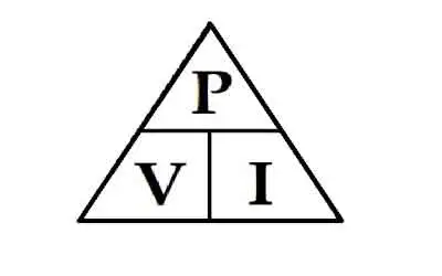
In AC circuits, active power (P) refers to the component of electrical power that results in energy transfer to a load. It is the energy that performs work—such as producing motion, light, or heat—and is distinct from reactive power, which oscillates between source and load without being consumed.

Active Power Formula

The general formula for active power is:

P = VIcosθ

Where:

  • P = Active Power (watts)

  • V = RMS Voltage

  • I = RMS Current

  • θ = Phase angle between voltage and current

In real-world power systems, only the portion of the current in phase with the voltage contributes to active power. The portion out of phase results in reactive power and does not produce usable energy.


Equation 1


The above active power equation is valid for both sinusoidal and nonsinusoidal conditions. For sinusoidal condition, '1rn, resolves to the familiar form,


Equation 2


Sinusoidal and Non-Sinusoidal Conditions

The calculation of active power can differ slightly depending on waveform distortion:

  • For sinusoidal conditions, Equation 1 simplifies to the standard P = VIcosθ form.

  • For non-sinusoidal waveforms, the total active power includes the sum of contributions from all harmonic components. However, since voltage distortion is typically below 5% in most power systems, the simplified equation is usually accurate enough for practical purposes.


Real-World Example

A standard incandescent light bulb converts electrical power into visible light and heat. This is a classic case of active power at work—where the current and voltage are in phase, and virtually all supplied power is consumed usefully.


Active vs Reactive vs Apparent Power

It’s important to distinguish active power from related concepts:

  • Reactive Power (Q): Energy exchanged but not consumed, measured in kVAR.

  • Apparent Power (S): The vector sum of active and reactive power, measured in kVA.

  • Power Factor: The ratio of active power to apparent power (PF = P/S).

While active power does the real work, apparent power impacts system loading and reactive power affects voltage stability. See our power factor training for more.


Measurement and Application

Active power is typically measured using true RMS meters that calculate the average of the instantaneous product of voltage and current. Advanced power analyzers now offer direct measurement of real power in both clean and distorted systems.

Engineers use active power data for:

  • Energy consumption analysis

  • Load management and optimization

  • System efficiency evaluation

  • Compliance with energy standards


Related Reading


Frequently Asked Questions


What is active power used for?

Active power is used to perform real work in electrical systems, such as lighting, heating, and running motors.


Is active power the same as real power?

Yes. Active power, real power, and true power are interchangeable terms that refer to the same concept.


How is active power calculated?

It is calculated using the formula P = VIcosθ, where V and I are RMS voltage and current, and θ is the phase angle between them.

In summary, understanding active power is essential for designing efficient electrical systems and ensuring energy accountability. By distinguishing it from reactive and apparent power, professionals can improve system performance and reduce energy losses.


Related Articles


View more

Sign Up for Electricity Forum’s Newsletter

Stay informed with our FREE Newsletter — get the latest news, breakthrough technologies, and expert insights, delivered straight to your inbox.

Electricity Today T&D Magazine Subscribe for FREE

Stay informed with the latest T&D policies and technologies.
  • Timely insights from industry experts
  • Practical solutions T&D engineers
  • Free access to every issue

Download the 2025 Electrical Training Catalog

Explore 50+ live, expert-led electrical training courses –

  • Interactive
  • Flexible
  • CEU-cerified