What is Medium Voltage iExplained

By R.W. Hurst, Editor


what is medium voltage

Medium voltage refers to electrical systems operating between 1 kV and 35 kV, used in industrial facilities, substations, and utility power distribution networks to safely transfer energy between low-voltage and high-voltage levels.


What is Medium Voltage?

Medium voltage refers to the electrical range between 1 kV and 35 kV, bridging the gap between low- and high-voltage systems for efficient energy transfer and safe power distribution across industrial, commercial, and utility applications.

✅ Used in substations, industrial plants, and utility grids

✅ Defined by IEEE and IEC classification standards

✅ Supports reliable energy transmission and electrical safety

A medium voltage (MV) system is crucial for distributing electricity in industrial, commercial, and institutional settings. It acts as the intermediary between high-voltage transmission lines and low-voltage consumer systems, ensuring efficient power delivery within a facility. This article provides a comprehensive overview of a medium voltage system, including its definition, applications, equipment, safety practices, and relevant standards. Understanding these concepts is vital for electrical professionals to ensure the safe and efficient operation of this critical power infrastructure. Medium voltage systems are essential links in 3 phase electricity networks, where balanced power delivery ensures efficient energy distribution across industrial and utility infrastructures.

Understanding medium voltage systems is essential for electrical professionals working in industrial, commercial, and institutional settings. This article provides a comprehensive overview of what constitutes medium voltage, its role in the power grid, common applications, and safety considerations. By grasping these key concepts, professionals can ensure the safe and efficient design, operation, and maintenance of these critical power systems. Understanding 3 phase power helps explain how medium voltage circuits maintain stable electrical loads in substations and manufacturing facilities.


Voltage Levels and Classifications

In the realm of electrical engineering, voltage levels are broadly categorized to distinguish their applications and safety requirements.  These categories range from LV, typically used for residential applications, to extra high voltage (HV) and ultra-high voltages employed in HV transmission across long distances. MV occupies a middle ground, generally falling between 1,000 volts (600 volts in some instances) and 35,000 volts (35 kV). This distinguishes it from HV used in transmission and lower voltages used in end-user applications. Many 3 phase transformers and pad-mounted transformer installations operate at medium voltage levels, stepping electrical energy down for safe use in local distribution systems.

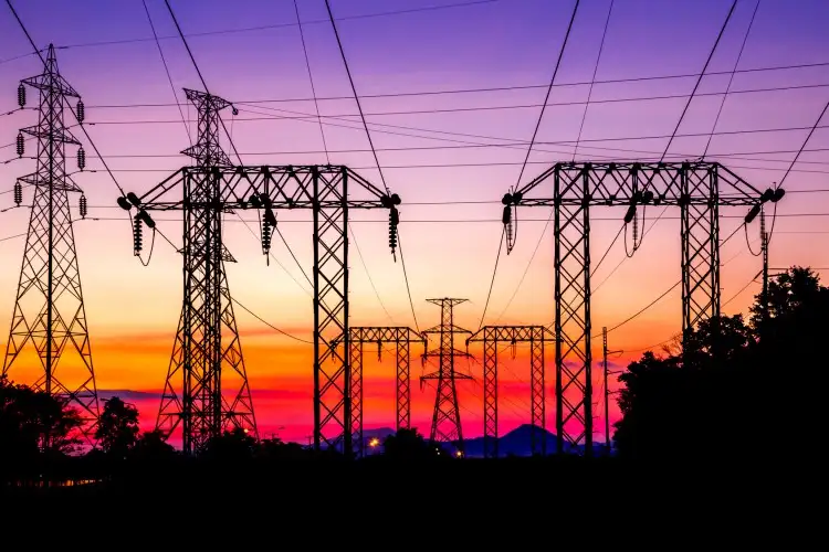
To better visualize this, imagine electricity flowing like a river through the electrical grid. V is like the force propelling the water, and different levels represent different sections of the river. HV is like a powerful, fast-flowing river capable of transporting electricity over long distances. MV, on the other hand, is like a branching stream that distributes the water (electricity) to various destinations. It's the crucial link between the high-powered transmission lines and the LV systems that deliver power to individual consumers. For a foundational understanding, review basic electricity concepts that explain how V, current, and resistance interact within medium voltage electrical systems.


What is Medium Voltage Applications?

Medium voltage systems have a wide range of applications in industrial, commercial, and institutional settings. In industrial facilities, they power large motors, heavy machinery, and industrial processes. Commercial buildings utilize what is MV for HVAC systems, lighting, and other electrical loads. Institutions such as hospitals and universities rely on MV to support their critical operations.

The use of MV is increasing. Historically, it was mainly used for subtransmission and primary distribution, supplying distribution transformers that step down the voltage to LV for end-use equipment. It was also traditionally used in industries for MV motors. However, with advancements in power electronics and semiconductor technology, new applications are emerging, such as:

  • MV DC Distribution Grids: These grids offer higher efficiency in long-distance transmission and are being implemented in collector grids for wind and photovoltaic parks.

  • Renewable Energy Integration: MV systems play a vital role in integrating renewable energy sources into the power grid, enabling the transition to a more sustainable energy future.

The principles of active power apply directly to medium voltage operations, where real power flow efficiency determines the overall performance of industrial and commercial grids.


Frequently Asked Questions


How does MV differ from low and HV?

Medium voltage occupies a middle ground between LV, typically used for residential applications, and HV, employed for long-distance transmission. It's the "in-between" voltage level that allows us to efficiently distribute power to different consumers.


What is Medium Voltage Range ?

Generally, MV falls between 1,000 volts (600 volts in some instances) and 35,000 volts (35 kV). This range can vary slightly depending on regional standards and practices.  For example, ANSI standards in the US include voltages up to 69 kV in the MV class, while IEC standards use 1000 Vrms as the threshold between low and HV in AC installations.


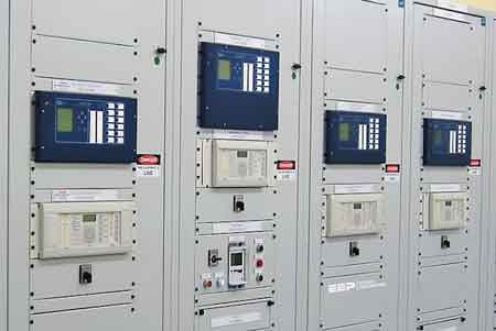
What is MV in industrial, commercial, and institutional power systems?

Medium voltage is distributed within these facilities to power various equipment and loads. It's the primary level used within these settings before being stepped down to LV for end-use.


What are common applications of MV systems?

Common applications include powering large motors and machinery in industrial settings, as well as HVAC and lighting systems in commercial buildings, and critical operations in institutions such as hospitals.  Emerging applications include microgrids and the integration of renewable energy.


What are the key standards and regulations governing MV systems?

Key standards include those from ANSI, IEEE, and NEC, which provide guidelines for the design, installation, and safety of MV systems. These standards ensure that MV systems are implemented in a safe and consistent manner.

A Medium Voltage system is crucial for distributing electricity in industrial, commercial, and institutional settings. It acts as the intermediary between HV transmission lines and LV consumer systems, ensuring efficient power delivery within a facility. This article provides a comprehensive overview of a medium voltage system, including its definition, applications, equipment, safety practices, and relevant standards. Understanding these concepts is vital for electrical professionals to ensure the safe and efficient operation of this critical power infrastructure.


Related Articles


Related News

Water Electricity

Water electricity refers to electrical power generated using water, primarily through hydroelectric systems. It converts the kinetic energy of moving or falling water into electricity, providing a renewable and sustainable energy source with low carbon emissions and high efficiency.


What is: “Water Electricity?”

Water electricity, also known as hydroelectric power, is energy derived from moving water. It’s a leading source of renewable electricity worldwide.

✅ Converts water’s kinetic energy into usable electricity

✅ Offers renewable, low-emission electricity generation

✅ Used in dams, rivers, and tidal energy systems

 Most hydroelectric power is generated from the potential energy of dammed water, which drives a water turbine and generator. Less common variations utilize water's kinetic energy or undammed sources, such as tidal power. Hydroelectricity is a renewable energy source.

The energy extracted from water depends not only on the volume but on the difference in height between the source and the water's outflow. This height difference is referred to as the head. The amount of potential energy in water is directly proportional to the head. To obtain a very high head of water for a hydraulic turbine, water may be run through a large pipe called a penstock.

While many supply public power networks, some Water Electricity projects were created for private commercial purposes. For example, aluminum processing requires substantial amounts of power, and in Britain's Scottish Highlands, there are examples at Kinlochleven and Lochaber, designed and constructed during the early 20th century. Similarly, the 'van Blommestein' lake, dam and power station were constructed in Suriname to provide power for the Alcoa aluminum industry. In many parts of Canada (specifically, the provinces of British Columbia, Manitoba, Ontario, Quebec, and Newfoundland and Labrador), hydroelectricity is used so extensively that the word "hydro" is often used to refer to any power delivered by a power utility. The government-run power utilities in these provinces are called BC Hydro, Manitoba Hydro, Hydro One (formerly "Ontario Hydro"), Hydro-Québec and Newfoundland and Labrador Hydro, respectively. Hydro-Québec is the world's largest hydroelectric generating company, with a total installed capacity (2005) of 31,512 MW. For deeper insight into how to generate electricity from various sources, including water, visit our guide on hydroelectricity, which explains methods, systems, and real-world examples.


Importance

Water and Electricity power supplies 20% of the world's electricity. Norway produces virtually all of its energy from hydroelectric sources. In contrast, Iceland produces 83% of its requirements (as of 2004), and Austria generates 67% of all power in the country from hydroelectric sources (over 70% of its total requirements). Canada is the world's largest producer of Water Electricity, and produces over 70% of its electric power from hydroelectric sources.

Apart from a few countries with an abundance of it, hydro capacity is normally applied to peak-load demand, because it can be readily stored during off-peak hours (in fact, pumped-storage hydroelectric reservoirs are sometimes used to store power produced by thermal plants for use during peak hours). It is not a major option for the future in developed countries because most major sites in these countries that have the potential for harnessing gravity in this way are either already being exploited or are unavailable for other reasons, such as environmental considerations.

Regions where thermal plants provide the dominant supply of power utilize Water Electricity to provide the important functions of load following and regulation. This permits thermal plants to be operated closer to thermodynamically optimal points rather than varied continuously, which reduces efficiency and potentially increases pollutant emissions. Concurrently, hydro plants are then utilized to provide for hour-to-hour adjustments and to respond to changes in system frequency and voltage (regulation), with no additional economic or environmental effect.


Related Articles


View more

Electromagnetic Induction

Electromagnetic induction is the process of generating electric current by changing a magnetic field, forming the basis for transformers, generators, and electric motors in power generation and energy conversion systems.


What is Electromagnetic Induction?

Electromagnetic induction is a fascinating and vital concept shaping how we generate, transfer, and utilize electricity.

✅ Process where a changing magnetic field induces an electric current in a conductor

✅ Fundamental principle behind transformers, generators, and electric motors

✅ Essential for modern power generation, transmission, and energy conversion


Its underlying principles, Faraday's Law and Lenz's Law, explain the phenomena occurring when magnetic fields interact with conductors. At the same time, its various applications, such as electric generators, transformers, induction heating, and wireless charging, have revolutionized our daily lives. As we continue to explore and understand this intricacy, we can look forward to even more innovations and advancements in electricity and magnetism. Understanding Faraday's Law is essential to grasp how changing magnetic fields generate electricity through electromagnetic induction.


Fundamental Laws of Electromagnetic Induction

Faraday's Law of electromagnetic induction, invented by Michael Faraday, is a key principle that states that the induced EMF in a coil is proportional to the rate of change of the magnetic flux (dφ/dt) passing through the coil. The more rapidly the magnetic field changes, the higher the amount of voltage induced will be. This relationship between electricity and magnetism laid the foundation for the development of various electrical devices and systems. The relationship between electricity and magnetism forms the foundation of generators, transformers, and other key electrical systems.

Lenz's Law, another crucial principle, explains the direction of the induced current. It states that the induced current will always flow in a direction that opposes the change in magnetic flux, acting as a stabilizing electromotive force. By combining Faraday's and Lenz's Law, we can better understand how it operates in real-world applications. For a deeper understanding of how voltage is produced in coils, explore the principles of Lenz's Law.


Core Applications: Generators and Transformers

One notable application is the electrical generator, which converts mechanical energy into electrical energy. In a typical generator, a coil of wire rotates within a magnetic field, creating a changing magnetic flux. This change induces a voltage and current in the coil, generating electricity. Generators are commonly used in power plants, automobiles, and other devices requiring a continuous electrical supply. A three-phase transformer uses electromagnetic induction to efficiently transfer power between circuits at different voltages.

Another critical application is the transformer, which transfers electrical energy between circuits with different voltages. Transformers consist of two induction coils wrapped around a shared magnetic core. When an alternating current flows through the primary coil, it creates a magnetic field that induces a voltage in the secondary coil. By adjusting the number of turns in the coils, transformers can step up or down the voltage as needed for specific electrical systems.


Special Phenomena: Eddy Currents, Mutual Inductance, and Self-Inductance

Eddy currents are an intriguing aspect of electromagnetic induction. These currents form when a magnetic field changes, causing swirling, closed loops of electric current within a conductor. Eddy currents generate heat and can lead to energy losses in electrical systems, but they also have practical applications, such as in metal detectors and induction heating. Devices that use electromagnetic induction, such as electric motors, rely on core principles of inductance to regulate energy transfer.

Two critical aspects of electromagnetic induction are mutual inductance and self-inductance. Mutual inductance occurs when the current in one coil induces a voltage in a nearby coil due to their shared magnetic field. Self-inductance refers to a coil's ability to induce a voltage within itself when the current flowing through it changes. Understanding these concepts is crucial for designing and analyzing complex electrical circuits and systems.


Demonstrating the Principle: Coil and Magnet Interaction

In many cases, it involves the interaction of a coil and a magnet, either a permanent magnet or an electromagnet. A bar magnet, for example, may be moved near a coil, or the coil may be moved about the magnet. This motion changes the magnetic field and induces a voltage in the coil, demonstrating the dynamic relationship between electricity and magnetism. Learning the basics of electrical resistance helps explain how eddy currents generate heat in conductive materials.


Modern Impact and Emerging Technologies

It has an immense impact on modern life, from generating electricity in power plants to operating devices like transformers, electric motors, and wireless chargers. The principles of Faraday's Law and Lenz's Law help explain the complex phenomena that occur when magnetic fields interact with conductors. By harnessing these principles, scientists and engineers have created various practical applications that have revolutionized our daily lives.

Electromagnetic induction demonstrates the fundamental relationship between electricity and magnetism and is integral to many aspects of our modern world. Faraday's Law and Lenz's Law underpin this phenomenon, governing the induced voltage and current when magnetic fields change. The applications of electromagnetic induction range from electric generators and transformers to the study of eddy currents, mutual in influence and self-inductance. By understanding these principles, we can continue to innovate and develop new technologies to improve our daily lives and advance our understanding of the world.


Induction Heating

Electromagnetic induction heating is another practical application that relies on electromagnetic induction. This technology utilizes eddy currents to heat conductive materials, such as metals. By placing a conductive material within a rapidly changing magnetic field, eddy currents are generated within the material, producing heat due to their resistance. This heating method has been employed in various industrial processes, including metal hardening, welding, and cooking.

Wireless charging is an emerging technology that utilizes electromagnetic induction to transfer energy between two coils. When an electric current flows through the primary coil, it generates a magnetic field, which induces a voltage in the secondary coil, providing power to the device. This technology has seen increasing adoption in recent years, particularly for charging electric vehicles and smartphones, offering convenience and reduced dependence on cords and cables.


Related Articles


View more

Basic Electricity – Understanding Current, Voltage, Resistance, and Power

Basic electricity refers to the fundamental concepts of electric charge, current, voltage, and resistance. It explains how electric circuits work, how energy flows, and how components like wires, batteries, and switches interact in homes, schools, and industries.


What is Basic Electricity?

Basic electricity refers to the foundational principles that explain how electric energy is generated, transmitted, and used in circuits. When an electric current flows through a conductor, it creates a magnetic field (or “flux”) around it.

✅ Explains current, voltage, resistance, and power in simple terms

✅ Describes how electric circuits operate and transfer energy

✅ Essential for understanding household wiring, batteries, and switches

Understanding the fundamentals of voltage is essential for grasping how electric circuits function — see our full explanation of voltage.

The strength of this magnetic field increases when the conductor is shaped into a coil with multiple turns. In electrical engineering, this coiled conductor is known as an inductor. If a steady direct current (DC) flows through the coil, it forms an electromagnet—an object with magnetic properties that can be switched on and off using a basic electrical switch.


Basic Electrical Theory

There are four basic electrical quantities that we need to know:

  • Current

  • Potential Difference (Voltage)

  • Power

  • Resistance


Electrical Current

Current is the movement of electric charge through a conductor. Each electron carries a charge of 1.6 × 10⁻¹⁹ coulombs—too small to measure individually—so we measure charge in groups called coulombs. When 1 coulomb of charge passes through a point in a circuit per second, the current is  1 ampere (A). Electric current is measured in amperes and is essential to the functioning of all electrical systems. Learn how voltage drop affects electrical performance and safety in residential and industrial systems. You can estimate losses in long-distance wiring with our easy-to-use voltage drop calculator. For step-by-step guidance on circuit loss calculations, explore the voltage drop formula explained clearly.


Potential Difference

Voltage, or potential difference, refers to the energy per unit charge in a circuit. It represents the work each charge can perform. Think of voltage as the electrical pressure that pushes electrons through a conductor. Higher voltage means more potential energy available to do work, such as lighting a bulb or powering a motor.


Power in a Circuit

Electrical power is the rate at which energy is used or transferred in a circuit. It can be calculated using the formula:

Power (W) = Voltage (V) × Current (A)

This equation is fundamental in both residential and industrial applications, from estimating energy usage to designing electrical systems.


Electrical Resistant Behaviour

Resistance is the opposition to the flow of electric current. It determines how much current will flow for a given voltage. Materials like copper have low resistance and conduct electricity well, while materials like rubber have high resistance and are used as insulators. Learn how voltage drop affects electrical performance and safety in residential and industrial systems.


Electromagnetic Induction

There’s a reciprocal relationship between electric current and magnetism. When a magnet is moved past a conductor at a right angle, it induces a voltage in the conductor—a principle known as electromagnetic induction. The polarity of the induced voltage depends on the direction and orientation of the magnetic field.

This effect becomes more noticeable when the conductor is formed into a coil. As the north pole of the magnet passes the coil, voltage is induced, and current flows. When the south pole passes, the induced voltage reverses polarity, and the current changes direction. This principle is the foundation of generator operation. You can estimate losses in long-distance wiring with our easy-to-use voltage drop calculator.


The Generator and the Sine Wave

In an electric generator, coils placed on opposite sides of a rotating magnet generate alternating current (AC). These voltages combine, doubling the output. For example, a 120-volt, 60-Hz generator creates a wave that oscillates from +169.7V to -169.7V.

This wave is called a sine wave because the voltage at any point corresponds to the sine of the magnet’s angle of rotation. The cycle repeats 60 times per second in North America (60 Hz), creating the household AC power we are familiar with. For step-by-step guidance on circuit loss calculations, explore the voltage drop formula explained clearly.


Forms of Electricity: AC and DC

Electricity exists in two major forms:

  • Alternating Current (AC): The direction of current flow alternates regularly. AC electricity is used in power grids because it is easier to transmit over long distances and is compatible with devices such as transformers and capacitors.

  • Direct Current (DC): The current flows steadily in one direction. DC is commonly used inside electronics and battery-powered devices. Unlike AC, the voltage remains constant, making it easy to measure with a DC voltmeter.


AC – Alternating Current

Alternating current is the most common form of electricity used in homes, businesses, and utilities. It alternates direction 50–60 times per second, depending on the region. AC is generated by AC generators and is favored for its ability to change voltage levels easily, making it efficient for transmission over long distances. Sudden dips in power can disrupt equipment — find out what causes voltage sag and how to prevent it.


DC – Direct Current

Direct current flows continuously in one direction. Because its voltage is steady or changes very slowly, it’s easy to measure. It is used in battery-powered systems and internal electronic circuits. Unlike AC, DC cannot be easily stepped up or down in voltage without the use of complex circuitry.

When calculating AC power, engineers use RMS (Root Mean Square) voltage, which gives an effective value comparable to DC. For example, 120V AC RMS is equivalent in power to 120V DC, despite the AC waveform's variations. Discover how water and electricity interact, including safety considerations and risks in common environments.


Transformers and Induction

Transformers, built using coiled wires around iron cores, rely on electromagnetic induction. When AC flows through the primary coil, it creates a changing magnetic field that induces a voltage in the secondary coil. This allows voltage to be stepped up or down for different uses, such as high-voltage transmission or low-voltage device operation.


Atoms, Electrons, and Electric Charge

To fully grasp electricity, it’s essential to understand atomic structure. All matter is made up of atoms, which contain a nucleus of protons (positive) and neutrons (neutral), surrounded by orbiting electrons (negative). The outermost electrons—called valence electrons—can be knocked loose by energy, creating an electric current.

When electrons leave an atom, it becomes positively charged. This movement of charge is the essence of electricity. The ability of atoms to gain or lose electrons determines whether a material is a conductor (like copper) or an insulator (like plastic).


Electrical Charge and Attraction

One universal rule in electricity and magnetism is that like charges repel and opposite charges attract. A positively charged object will attract a negatively charged one. This principle governs everything from how circuits function to how magnetic fields interact with conductors. To understand how energy use is measured over time, read our overview of the watthour meter and its function.


Related Articles


View more

Hydroelectricity Explained

Hydroelectricity converts hydropower into grid-ready electricity using dams, penstocks, turbines, and generators, enabling renewable baseload, pumped storage, high efficiency, and low emissions for resilient power systems with load balancing, frequency regulation, and strong capacity factors.


What Is Hydroelectricity?

Hydroelectricity is electricity generated by water turning turbines at dams, delivering low-carbon power to the grid.

✅ Converts hydraulic head and flow into alternating current.

✅ Uses synchronous generators, excitation, and step-up transformers.

✅ Supports grid inertia, regulation, and pumped-storage balancing.


Hydroelectricity is another term for power generated by harnessing the power of damming rivers and moving water into generating plants. Not necessarily falling water, just moving water. There are many famous such Hydroelectricity stations in the world, not the least of them at Niagara Falls, Grand Coulee and Boulder Dam and the three gorges dam in China . In the past, small plants produced electric hydroelectricity. Now, they are massive in size and generation capcity as well as having large reservoirs. If there is a need for power electrical generation stations situated close to the point of consumption is ideal. These are just a few of the many examples of energy produced by falling water. On the other hand, a small mill set in the rapids of a fast-moving stream is also an example of it in action, on a lesser scale. The truth is that any steady current of flowing water from a river or other waterway can be converted to power. Of all the sources electricity from hydroelectricity, dammed reservoirs is one of the cleanest possibe ways to generate electricity to a million people, compared with nuclear power. For broader background on water safety and power concepts, the guide on water and electricity explains interactions, risks, and basic generation principles.


How is HydroElectricity Generated?

Hydroelectricity is generated or "manufactured" in large hydroelectric plants, (electrical generating stations) using the same basic principle as a small grist mill yet on a much larger and vastly improved scale for better efficiency, using pumped storage. These power plants contain electrical generators which are attached to massive turbine devices which spin at great speeds as a result of water rushing through them. These pump water power station turbines are much more efficient at extracting the kinetic energy from the moving water and converting that energy it into electrical production through these generators. To see how hydro fits within the wider energy landscape, review how electricity is generated across different prime movers and grid systems.

The amount of electricity from Hydroelectricity extracted from water as an energy source depends not only on the capacities of volume sent through a hydroelectric power plant but on the difference in height between the source and the water's outflow. This height difference is called the head. The amount of potential energy in water is directly proportional to the head and how much water is released. To obtain very high head, water for a hydraulic turbine may be run through a large pipe called a penstock. These relationships between flow, head, and output are core electricity generation principles that guide plant design and optimization.

For instance, energy is derived to make electricity water has to move from a higher elevation to a lower elevation through a large tube" otherwise known in technical terms as a "penstock". When the water reaches the end of the penstock, it turns a water wheel or "turbine" at enormous speeds. The turbine rotates, via a connected shaft to an electrical generator, and this generator creates electricity. It is the turbine and generator working in combination that converts "mechanical energy" into "electric energy". The water that makes this possible, is a renewable energy resource, just like the wind that turns the turbine attached to a generator. This mechanical-to-electrical conversion is a classic way to generate electricity efficiently when hydraulic conditions are favorable.

Hydroelectricity may be extracted from water but it depends not only on the volume of water but also on the difference in height between the top of the penstock and where the water spins the turbine. This difference in height is often referred to as the "head". From this "head", it can be determined the exact amount of potential energy that can be converted. Therefore, it is advantageous to build power dams as high as possible to convert the maximum energy from mechanical energy. Project planners evaluate head, flow duration, and dispatch needs in the context of overall electricity production targets and grid reliability.

While many hydroelectricity generating stations supply world power grids, some projects are created for private business purposes. For example, aluminium manufacturing companies require large amounts of power. And there are many other examples of industries that use hydroelectricity in their manufacturing operations. Industrial facilities often diversify procurement among various sources of electricity to balance costs, resilience, and sustainability goals.

While hydroelectricity in the United States seems relatively clean and safe in comparison to burning fossil fuels (coal or oil or natural gas), nearly all large hydroelectricity installations in North America have significant had impacts on nearby environmental habitats once they are brought online. This is because they significantly impede the flow of water in rivers and lakes at the point where the generating dam is installed In turn, this causes significant increases in water levels in corresponding upstream water systems while at the same time creating much lower water levels downstream. Mitigation strategies may include fish passages, adaptive flow management, and complementary alternative electricity options to reduce ecological disruption.


Related Articles

View more

Electricity Grid - T&D

Electricity grid infrastructure delivers power through transmission lines, substations, and smart grid controls, balancing voltage and frequency, integrating renewable energy, enabling demand response, improving reliability, and supporting utilities with real-time monitoring and load management.


What Is the Electricity Grid?

A network of transmission, distribution, and control systems that delivers reliable electrical power to consumers.

✅ Transmits high-voltage power from plants to local networks

✅ Steps down voltage at substations for safe distribution

✅ Integrates renewables with smart grid and demand response


The electricity grid is a complex and essential component of modern society. It provides the power necessary to operate homes, businesses, and industries, and it is constantly evolving to meet the demands of a changing world. From power generation to distribution, transmission lines to load balancing and renewable energy integration, every component is critical in ensuring we can access reliable and affordable energy whenever needed. For a broader primer, resources such as electric power systems outline how these elements interconnect in practice.

At its core, the grid is a system that connects power generation facilities to consumers through transmission lines and distribution systems. It is designed to move electricity from where it is generated to where it is needed, whether in a residential home or a large industrial facility. The term "grid" refers to the interconnectedness of these systems, which allows power to flow from one location to another as needed. The federal energy regulatory commission ferc regulates the grid.

In North America, the transmission and distribution (T&D) grid is managed by federal, state, provincial, and territorial agencies. The grid is divided into various regions, each with its grid operator responsible for ensuring reliable and efficient operation within their respective jurisdiction. For instance, Canada's power delivery network is divided into four main regions: Western Canada, Ontario, Quebec, and the Atlantic region. Similarly, the United States' electricity grid is divided into three major interconnected systems: the Eastern Interconnection, Western Interconnection, and the Electric Reliability Council of Texas (ERCOT) system. Each region's grid operator works closely with neighbouring grid operators to ensure a seamless flow of electrical power across the interconnected grid, even during periods of high demand or unexpected outages.

The power delivery network can be broken down into three main components: power generation, transmission, and distribution. Power generation facilities can take many forms, including coal-fired, natural gas, nuclear, and renewable energy sources such as wind and solar. These facilities generate electrical power transmitted over high-voltage transmission lines to substations, where the voltage is lowered for distribution to homes and businesses through a network of distribution lines. For those new to supply technologies, overviews of how electricity is generated cover conventional and renewable pathways.

Transmission lines are a critical component of the T&D system, which deliver and produce electricity at higher voltages. T&D provides the means to move large amounts of electrical power over long distances. These lines are typically made of high-strength steel or aluminum and span hundreds of miles. They are also designed to be highly resilient to extreme weather events such as hurricanes, tornadoes, and ice storms. Understanding ratings, capacity, and losses draws on electricity power fundamentals that inform planning and operations.

The distribution system is the final component of the power grid, responsible for delivering electrical power directly to homes and businesses. This system includes transformers, power lines, and meters, which work together to regulate power flow to individual consumers. The distribution system also includes local power generation facilities, such as rooftop solar panels and small-scale wind turbines, which can supplement the power provided by the grid. To see how fuel mixes influence local grids, summaries of sources of electricity highlight regional differences.

As the world increasingly relies on electrical power, there is a growing need to modernize and upgrade the power delivery network to meet the demands of the 21st century. One approach to this is the development of a smart grid, which uses advanced sensors, communication networks, and analytics to optimize the flow of power and improve reliability. Another approach is the integration of renewable energy sources such as wind and solar into the grid, which can reduce greenhouse gas emissions and improve grid resilience. Advanced planning and forecasting increasingly leverage power system analysis to evaluate contingencies and optimize investments.

Load balancing is another critical function, ensuring that real-time power generation and consumption are matched. This is accomplished through a combination of forecasting, automated control systems, and energy storage facilities such as batteries and pumped hydroelectric storage. In flexible markets, insights into electricity generation help operators schedule resources effectively.

Reliability and resilience are also crucial factors in its overall performance. The grid must be designed to withstand extreme weather events and other disruptions, such as cyberattacks or equipment failures. This requires a combination of robust engineering and effective emergency response planning.


What is an electricity grid, and how does it work?

A T&D system is a complex network of power generation facilities, transmission lines, and distribution systems that work together to ensure reliable and affordable energy is available to consumers. At its core, the grid is a system that connects power generation facilities to consumers through transmission lines and distribution systems. It is designed to move electrical power from where it is generated to where it is needed, whether in a residential home or a large industrial facility. The grid uses high-voltage transmission lines to move electrical power over long distances, then lowers the voltage through transformers for distribution to homes and businesses. For foundational clarity, a concise explainer on what electricity is helps connect basic concepts to grid operations.


What is the difference between the transmission and distribution systems?

The transmission system is responsible for moving large amounts of electrical power over long distances at high voltages. This is accomplished through a network of high-voltage transmission lines and substations spanning hundreds of miles. The distribution system delivers electrical power directly to homes and businesses at lower voltages. This system includes transformers, power lines, and meters, which work together to regulate the flow of electricity to individual consumers.


How is renewable energy integrated?

Renewable energy sources such as wind and solar are integrated into the T&D system through a process called interconnection. This involves connecting the renewable energy source to the grid through a substation and transformer, ensuring that the energy generated can be transmitted to consumers. Renewable energy sources can also be connected to the grid through distributed generation, where energy is generated on-site at the point of consumption, such as through rooftop solar panels.


What are the challenges associated with maintaining the reliability and resilience of the T&D system?

Maintaining reliability and resilience is a complex task requiring robust engineering and effective emergency response planning. Some of the challenges associated with this include extreme weather events, cyberattacks, equipment failures, and natural disasters. In addition, as the grid becomes more reliant on renewable energy sources, new challenges may arise related to load balancing and energy storage.


What is a smart grid, and how does it differ from a traditional T&D system?

A smart grid is a modernized version of the traditional T&D system that uses advanced sensors, communication networks, and analytics to optimize the flow of electrical power and improve reliability. Unlike a traditional T&D system, designed to move electrical power from power plants to consumers, a smart grid enables two-way communication between consumers and the grid. This allows for greater control and flexibility in managing energy usage and improved efficiency and reliability.


How can energy storage be used to support the T&D system?

Energy storage can be used to support the T&D system in several ways. One essential function is to provide backup power in the event of a blackout or other disruption to the grid. Energy storage can also help balance the load on the grid, ensuring that power generation and consumption are matched in real-time. In addition, energy storage can help integrate renewable energy sources into the grid by storing excess energy for use during times of low generation.


What is grid modernization, and why is it important for the future of the T&D system?

Grid modernization refers to upgrading and improving the T&D system to meet the demands of a changing world. This may involve the development of a smart grid, the integration of renewable energy sources, and the deployment of advanced sensors and control systems. Grid modernization is important for the future of the T&D system because it will enable greater efficiency, reliability, and sustainability while ensuring that the grid is resilient to emerging threats and challenges.


Related Articles

View more

Kirchhoff's Law

Kirchhoff's Law, comprising the Current Law (KCL) and Voltage Law (KVL), governs electrical circuits by ensuring charge conservation and energy balance, essential for analyzing current flow, voltage drops, and network behaviour.


What is Kirchhoff's Law?

Kirchhoff's law is an essential principle in the analysis of electrical circuits, enabling a comprehensive understanding of the behaviour of complex circuits.

✅ Defines relationships between currents and voltages in electrical circuits

✅ Ensures conservation of charge (KCL) and energy (KVL) in networks

✅ Essential for analyzing and solving complex circuit problems

It consists of two fundamental rules, Kirchhoff's Current Law (KCL) and Kirchhoff's Voltage Law (KVL), which are intrinsically linked to other electricity laws, such as Ohm's law.  Kirchhoff’s Law works closely with Ohm’s Law Formula to calculate voltage drops, currents, and resistance in electrical networks.

Kirchhoff's Current Law (KCL) - Also known as the first Kirchhoff's law or Kirchhoff's junction rule, KCL states that the sum of the currents entering a junction in a circuit is equal to the sum of the currents leaving the junction. Mathematically, it can be expressed as:

ΣI_in = ΣI_out

KCL is based on the principle of the conservation of charge, asserting that charge can neither be created nor destroyed. In practical terms, KCL means that, at any given point in a circuit, the total current entering must equal the total current leaving, ensuring a continuous flow of electric charge. Understanding Basic Electricity provides the foundation for applying Kirchhoff’s Current Law and Voltage Law to real-world circuit analysis.

Kirchhoff's Voltage Law (KVL) - Also known as the second Kirchhoff's law or Kirchhoff's loop rule, KVL states that the sum of the voltage gains and losses (potential differences) around any closed loop in a circuit is zero. Mathematically, it can be expressed as:
ΣV_rise = ΣV_drop

KVL is based on the principle of the conservation of energy, indicating that energy cannot be created or destroyed but can only be converted from one form to another. In electrical circuits, KVL implies that the total voltage supplied in a loop equals the total voltage drop across all components, ensuring that energy is conserved. Accurate circuit calculations require a clear grasp of Electrical Resistance and how it impacts voltage distribution across components.


Relation to Other Electricity Laws

The most significant connection between Kirchhoff's and other electricity laws is Ohm's law, which defines the relationship between voltage, current, and resistance in an electrical circuit. Ohm's law can be expressed as:

V = IR

When analyzing a circuit using Kirchhoff's laws, Ohm's law is often employed to calculate unknown quantities such as voltage drops, currents, or resistance values. By combining Kirchhoff's laws with Ohm's law, a complete understanding of the behaviour of electrical circuits can be achieved, facilitating efficient design, troubleshooting, and optimization. Applying Kirchhoff’s principles is easier when you understand key Electrical Terms used in engineering and troubleshooting.


History

Gustav Robert Kirchhoff, a German physicist, made significant contributions to understanding electrical circuits by establishing two fundamental laws: Kirchhoff's Voltage Law (KVL) and Kirchhoff's Current Law (KCL). These laws are essential tools for circuit analysis, enabling engineers to design and troubleshoot electrical networks efficiently. In addition to resistance, Capacitance plays a vital role in determining circuit behavior, especially in AC systems.

KVL, also known as the loop rule, states that the algebraic sum of all the voltages around a closed loop equals zero. This principle is derived from the conservation of energy, which ensures that no energy is lost within a closed system. In essence, KVL states that the energy supplied to a circuit is equal to the energy consumed by the components in that circuit. Therefore, when solving problems using KVL, it is essential to consider voltage drops across resistive elements like resistors and voltage rises due to sources like batteries or generators.

On the other hand, KCL, or the junction rule, states that the algebraic sum of currents entering a junction (node) in a circuit is equal to the sum of currents leaving the same junction. This law is a consequence of the conservation of charge, which posits that charge cannot be created or destroyed within an electrical circuit. KCL ensures that the total charge entering and leaving a node remains constant, with the currents (I1, I2, I3, I4, I5) balancing each other. Knowledge of Voltage Drop is essential when using KVL to assess energy losses in electrical circuits.

The significance of these laws in electrical networks lies in their versatility, as they can be applied to a wide range of circuits, from simple series and parallel circuits to more complex electrical networks. Kirchhoff's laws can be employed in conjunction with Ohm's Law, which states that the current through a conductor is proportional to the voltage across it and inversely proportional to its resistance. Using Kirchhoff's and Ohm's Law, engineers can analyze various aspects of a circuit, including voltage drops, current flow, and power distribution.

When analyzing series and parallel circuits, his laws offer valuable insight into the behaviour of electrical components. In series circuits, the current remains constant throughout the entire loop, while the voltage drops across each resistor are proportional to their respective resistances. The voltage across each branch is constant in parallel circuits, but the current is divided among the parallel resistors according to their resistances. By applying KVL and KCL to these configurations, engineers can determine the optimal arrangement of components for a given application.

To illustrate the application of his laws, consider a simple example. Imagine a circuit with a battery, two resistors in series, and a capacitor in parallel with the second resistor. By applying KVL and KCL, we can determine the voltage drop across each resistor, the current flow through each branch, and the voltage across the capacitor, enabling us to analyze the circuit's behaviour under various conditions.

Despite their usefulness, his laws have some limitations and assumptions. For instance, they assume that the components in a circuit are ideal, meaning they have no internal resistance or capacitance. Additionally, they don't account for the effects of electromagnetic fields or the finite speed of signal propagation in AC circuits. However, these limitations are often negligible in many practical applications, as they only marginally impact circuit performance. For a deeper historical context, explore the History of Electricity and the contributions of Gustav Kirchhoff to modern circuit theory.


Related Articles


View more

Sign Up for Electricity Forum’s Newsletter

Stay informed with our FREE Newsletter — get the latest news, breakthrough technologies, and expert insights, delivered straight to your inbox.

Electricity Today T&D Magazine Subscribe for FREE

Stay informed with the latest T&D policies and technologies.
  • Timely insights from industry experts
  • Practical solutions T&D engineers
  • Free access to every issue

Download the 2025 Electrical Training Catalog

Explore 50+ live, expert-led electrical training courses –

  • Interactive
  • Flexible
  • CEU-cerified