Ampere's Law Explained

By R.W. Hurst, Editor


ampere's law

Ampere’s Law describes the relationship between magnetic fields and electric currents, a fundamental concept in electromagnetism. It explains how current produces a magnetic force, guiding the design of circuits, solenoids, coils, and transformers in electrical engineering.


What is Ampere’s Law?

Ampere's Law is a fundamental principle in electromagnetism that describes the relationship between electric current and the resulting magnetic field.

✅ It states that the magnetic field around a closed path is proportional to the electric current passing through it.

✅ It is a fundamental principle of electromagnetism, linking current and magnetic flux.

✅ Used in analyzing coils, solenoids, transformers, and magnetic circuits.

Named after the French physicist André-Marie Ampère, this powerful principle helps us understand the behaviour of magnetic fields generated by electric currents. It is crucial to develop the numerous technologies we use on a daily basis. Understanding Ampere's Law is easier when explored alongside related concepts in basic electricity, which provide the foundation for electrical theory.

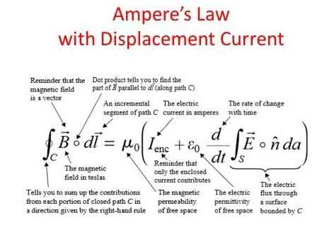
The principle states that the line integral of a magnetic field (B) around a closed loop is equal to the product of the permeability of free space (μ₀) and the net electric current (I) passing through the loop. This can be mathematically represented as:

∮ B⋅dl = μ₀I


Ampere’s Law at a Glance

Aspect Explanation Example / Application
Definition Magnetic field around a closed loop is proportional to the net electric current passing through it. Helps calculate fields in wires, coils, solenoids.
Formula ∮ B · dl = μ₀I (line integral of magnetic field equals permeability × current). Used in physics and engineering calculations.
Relation to Biot-Savart Law Both describe magnetic fields from current. Biot-Savart handles complex geometries; Ampere’s Law suits symmetrical setups. Magnetic field around a straight wire vs. irregular current paths.
Relation to Faraday’s Law Ampere’s Law: current → magnetic field. Faraday’s Law: changing magnetic field → induced EMF. Motors, generators, induction coils.
Role in Maxwell’s Equations One of the four fundamental equations of electromagnetism. Describes interaction of electric and magnetic fields.
Key Devices Guides design of solenoids, transformers, inductors, motors, and generators. Power systems, telecommunications, energy conversion.
Real-World Impact Essential to modern technology relying on electromagnetism. Smartphones, computers, power grids, antennas.


Ampere’s Law and Magnetism

The principle can be applied to determine the magnetic field around current-carrying wires and other conductive materials, as well as within various electrical systems. It is an essential part of Maxwell's equations, a set of four equations that serve as the foundation of classical electromagnetism. These equations relate electric and magnetic fields to their sources (electric charges and currents) and describe how they propagate through space. The connection between electricity and magnetism is central to electromagnetism, where Ampere’s Law works hand-in-hand with Faraday’s Law to explain induction.

It calculates magnetic fields through the Biot-Savart Law, a mathematical expression that relates the magnetic field produced by a steady electric current to the current's geometry. Both principles have specific applications, with the Biot-Savart Law being more suitable for cases with intricate current configurations. At the same time, it is typically employed when dealing with symmetrical setups.

Ampere’s Law has numerous real-life applications, especially in developing and understanding devices and systems that involve electromagnetism. For example, it is used in the design of transformers, inductors, and solenoids, as well as in various applications such as telecommunications systems, motors, and generators. By applying it, engineers can predict and control the magnetic fields generated in these devices, ensuring they function optimally and efficiently.


Gauss’ Law and Electric Fields Around a Circle of Radius

When studying electromagnetism, a common problem is analyzing the behavior of electric fields around a symmetric object, such as a circle of radius r or a sphere. Gauss’ Law is especially powerful in such cases, because it states that the electric flux through a closed surface is proportional to the net charge enclosed. This means the distribution of field lines can be calculated without solving complex integrals directly.

For a uniformly charged circle of radius r, the electric field at a point along the axis can be derived by considering the superposition of contributions from each charge element. The result reveals that the electric field depends on both the radius of the circle and the distance from the observation point. This demonstrates how Gauss’ Law simplifies problems with high symmetry.

Mathematically, the relationship is expressed as:

∮ E · dA = Q / ε₀

Here, E represents the vector field of the electric field, dA is the infinitesimal area vector on the closed surface, Q is the enclosed charge, and ε₀ is the permittivity of free space. By applying this principle, one can determine that electric fields radiate symmetrically outward from charges, with strength diminishing with distance according to the geometry of the surface considered.

The application of Gauss’ Law in analyzing a circle of radius r is connected to Ampere’s Law, as both emphasize symmetry and integration around closed paths. Where Ampere’s Law links magnetic fields to current, Gauss’ Law links electric fields to charge, and together they form part of Maxwell’s equations, the foundation of electromagnetism.


Relationship between Ampere's Law and Faraday's Law

The relationship between Ampere's Law and Faraday's Law of electromagnetic induction is apparent in the phenomenon of electromagnetic induction itself. When a changing magnetic field induces an electric current in a conductive material, the resulting magnetic field generated by this electric current, in turn, affects the overall magnetic field. It helps us understand how these interacting magnetic fields behave and influence each other.

Ampere's Law and its applications in various devices and systems enable numerous technological advancements. For instance, when designing motors and generators, engineers can utilize the principle to optimize the magnetic field within the device, resulting in higher efficiency and improved performance. Ampere’s Law is also linked to the behavior of capacitance and inductance, both of which are essential in circuits and energy storage systems.

In the telecommunications realm, it helps explain the propagation of electromagnetic waves in cables and antennas. It enables engineers to design systems that minimize signal loss and maximize data transfer rates, ensuring that our smartphones, computers, and other devices remain connected and up-to-date.

By understanding the magnetic field lines and the interaction between electric current and magnetic fields, Ampere's Law opens doors to scientific discovery and innovation in numerous fields. From determining the magnetic field at a distance to the thumb rule and hand rule applications, this fundamental principle plays a crucial role in shaping the world of electromagnetism and the technology that surrounds us.


Electromagnetism

It is a cornerstone of electromagnetism that helps us understand the relationship between electric current and how it creates a magnetic field. It is a vital component of Maxwell's equations and intricately connected to other principles, such as Faraday's Law and Biot-Savart's Law. Ampere's Law has numerous applications in real-life scenarios and is essential for the functioning of many devices and systems that rely on electromagnetism. Its significance in the development of technology cannot be overstated, as it continues to drive scientific discovery and innovation. For students exploring fundamentals, the history of concepts like what is electricity and its evolution in electricity history provides valuable context to Ampere’s discoveries.


How does Ampere’s Law relate to Faraday's Law and Biot-Savart Law?

They are all essential principles in electromagnetism that describe various aspects of the interaction between electric currents and magnetic fields. Although each addresses different aspects, these are interrelated, forming a more comprehensive understanding of electromagnetism.

It describes the relationship between an electric current and its generated magnetic field. Mathematically, it states that the line integral of the magnetic field (B) around a closed loop is proportional to the net electric current (I) passing through the loop:

∮ B⋅dl = μ₀I

Ampere’s Law is useful for calculating magnetic fields in highly symmetrical situations, such as around straight wires, loops, or solenoids.

Faraday's Law: Faraday's Law of Electromagnetic Induction describes how a changing magnetic field induces an electromotive force (EMF) in a conductor. Mathematically, it states that the induced EMF is proportional to the rate of change of the magnetic flux (ΦB) through a closed loop formed by the conductor:

EMF = -dΦB/dt

Faraday's Law is fundamental to understanding the operation of devices such as generators, transformers, and induction motors, which rely on converting mechanical and electrical energy.

The Biot-Savart Law calculates the magnetic field at any point in space due to a specific current distribution. Mathematically, it can be expressed as:

dB = (μ₀ / 4π) * (Idl × r̂) / r²

The Biot-Savart Law is particularly useful for calculating magnetic fields in complex current configurations without symmetry.


Ampere's Law and Biot-Savart Law

Ampere's Law and Biot-Savart Law: Both deal with the magnetic field generated by an electric current. While the first is useful for calculating magnetic fields in symmetric situations, the Biot-Savart Law applies to a wider range of configurations, including those with intricate geometries. It can be derived from the Biot-Savart Law for specific symmetric situations.


Ampere's Law and Faraday's Law

Ampere's Law and Faraday's Law: These laws are related through Maxwell's equations, which connect electric and magnetic fields. While the first deals with the magnetic field generated by a steady electric current, Faraday's Law deals with the induced EMF resulting from a changing magnetic field. Both laws contribute to our understanding of electromagnetic phenomena and play a role in operating devices that rely on electromagnetism.

The Biot-Savart Law enables us to determine the magnetic field generated by a specific current distribution. Faraday's Law describes how a changing magnetic field can induce an EMF. In cases where the magnetic field changes due to a varying current, the Biot-Savart Law can be used to calculate the magnetic field, and then Faraday's Law can be applied to determine the induced EMF.

All three are interconnected principles in electromagnetism, each addressing a specific aspect of the interaction between the electric current and the electric field. Together, these form a more comprehensive understanding of electromagnetic phenomena and provide a basis for analyzing and designing various devices and systems that rely on electromagnetism.


Related Articles


Related News

What is Medium Voltage iExplained

Medium voltage refers to electrical systems operating between 1 kV and 35 kV, used in industrial facilities, substations, and utility power distribution networks to safely transfer energy between low-voltage and high-voltage levels.


What is Medium Voltage?

Medium voltage refers to the electrical range between 1 kV and 35 kV, bridging the gap between low- and high-voltage systems for efficient energy transfer and safe power distribution across industrial, commercial, and utility applications.

✅ Used in substations, industrial plants, and utility grids

✅ Defined by IEEE and IEC classification standards

✅ Supports reliable energy transmission and electrical safety

A medium voltage (MV) system is crucial for distributing electricity in industrial, commercial, and institutional settings. It acts as the intermediary between high-voltage transmission lines and low-voltage consumer systems, ensuring efficient power delivery within a facility. This article provides a comprehensive overview of a medium voltage system, including its definition, applications, equipment, safety practices, and relevant standards. Understanding these concepts is vital for electrical professionals to ensure the safe and efficient operation of this critical power infrastructure. Medium voltage systems are essential links in 3 phase electricity networks, where balanced power delivery ensures efficient energy distribution across industrial and utility infrastructures.

Understanding medium voltage systems is essential for electrical professionals working in industrial, commercial, and institutional settings. This article provides a comprehensive overview of what constitutes medium voltage, its role in the power grid, common applications, and safety considerations. By grasping these key concepts, professionals can ensure the safe and efficient design, operation, and maintenance of these critical power systems. Understanding 3 phase power helps explain how medium voltage circuits maintain stable electrical loads in substations and manufacturing facilities.


Voltage Levels and Classifications

In the realm of electrical engineering, voltage levels are broadly categorized to distinguish their applications and safety requirements.  These categories range from LV, typically used for residential applications, to extra high voltage (HV) and ultra-high voltages employed in HV transmission across long distances. MV occupies a middle ground, generally falling between 1,000 volts (600 volts in some instances) and 35,000 volts (35 kV). This distinguishes it from HV used in transmission and lower voltages used in end-user applications. Many 3 phase transformers and pad-mounted transformer installations operate at medium voltage levels, stepping electrical energy down for safe use in local distribution systems.

To better visualize this, imagine electricity flowing like a river through the electrical grid. V is like the force propelling the water, and different levels represent different sections of the river. HV is like a powerful, fast-flowing river capable of transporting electricity over long distances. MV, on the other hand, is like a branching stream that distributes the water (electricity) to various destinations. It's the crucial link between the high-powered transmission lines and the LV systems that deliver power to individual consumers. For a foundational understanding, review basic electricity concepts that explain how V, current, and resistance interact within medium voltage electrical systems.


What is Medium Voltage Applications?

Medium voltage systems have a wide range of applications in industrial, commercial, and institutional settings. In industrial facilities, they power large motors, heavy machinery, and industrial processes. Commercial buildings utilize what is MV for HVAC systems, lighting, and other electrical loads. Institutions such as hospitals and universities rely on MV to support their critical operations.

The use of MV is increasing. Historically, it was mainly used for subtransmission and primary distribution, supplying distribution transformers that step down the voltage to LV for end-use equipment. It was also traditionally used in industries for MV motors. However, with advancements in power electronics and semiconductor technology, new applications are emerging, such as:

  • MV DC Distribution Grids: These grids offer higher efficiency in long-distance transmission and are being implemented in collector grids for wind and photovoltaic parks.

  • Renewable Energy Integration: MV systems play a vital role in integrating renewable energy sources into the power grid, enabling the transition to a more sustainable energy future.

The principles of active power apply directly to medium voltage operations, where real power flow efficiency determines the overall performance of industrial and commercial grids.


Frequently Asked Questions


How does MV differ from low and HV?

Medium voltage occupies a middle ground between LV, typically used for residential applications, and HV, employed for long-distance transmission. It's the "in-between" voltage level that allows us to efficiently distribute power to different consumers.


What is Medium Voltage Range ?

Generally, MV falls between 1,000 volts (600 volts in some instances) and 35,000 volts (35 kV). This range can vary slightly depending on regional standards and practices.  For example, ANSI standards in the US include voltages up to 69 kV in the MV class, while IEC standards use 1000 Vrms as the threshold between low and HV in AC installations.


What is MV in industrial, commercial, and institutional power systems?

Medium voltage is distributed within these facilities to power various equipment and loads. It's the primary level used within these settings before being stepped down to LV for end-use.


What are common applications of MV systems?

Common applications include powering large motors and machinery in industrial settings, as well as HVAC and lighting systems in commercial buildings, and critical operations in institutions such as hospitals.  Emerging applications include microgrids and the integration of renewable energy.


What are the key standards and regulations governing MV systems?

Key standards include those from ANSI, IEEE, and NEC, which provide guidelines for the design, installation, and safety of MV systems. These standards ensure that MV systems are implemented in a safe and consistent manner.

A Medium Voltage system is crucial for distributing electricity in industrial, commercial, and institutional settings. It acts as the intermediary between HV transmission lines and LV consumer systems, ensuring efficient power delivery within a facility. This article provides a comprehensive overview of a medium voltage system, including its definition, applications, equipment, safety practices, and relevant standards. Understanding these concepts is vital for electrical professionals to ensure the safe and efficient operation of this critical power infrastructure.


Related Articles


View more

Power System Analysis Explained

Power System Analysis enables load flow studies, fault calculations, stability assessment, state estimation, and contingency analysis for grids, integrating SCADA data, protection coordination, and reliability planning to optimize transmission, distribution, and generation performance.


What Is Power System Analysis?

Power System Analysis models grid behavior to ensure stability, reliability, efficiency, and secure operation.

✅ Load flow, short-circuit, and transient stability studies

✅ State estimation, SCADA integration, and contingency analysis

✅ Protection coordination, reliability assessment, and optimization


Power system analysis (PSA) is an essential electrical system component. It helps to ensure that the electrical system operates efficiently, reliably, and safely. Power flow analysis, fault study, stability investigation, renewable energy integration, grid modernization, and optimization techniques are all essential concepts in PSA. As our society continues to rely heavily on electricity, PSA will remain a vital tool for ensuring the stability and reliability of the electrical system. For foundational context on how electricity underpins these studies, see this primer on what electricity is and how it behaves.

One of the critical concepts in PSA is power system modelling. Modelling is creating a mathematical model of the electrical system. This model includes all the system components, such as generators, transformers, transmission lines, and distribution networks. Modelling is essential as it provides a detailed understanding of the system's workings. Engineers commonly begin by drafting a single-line diagram to visualize component interconnections and power paths.

Another critical concept in PSA is power flow investigation, also known as load flow investigation. Power flow analysis calculates the electrical system's voltages, currents, and power flows under steady-state conditions. A power flow study helps determine whether the electrical system can deliver electricity to all the loads without overloading any system component. The results of the power flow investigation are used to plan the system's expansion and ensure that it operates efficiently and reliably. In practice, load-flow outputs are interpreted within the broader context of electric power systems to validate voltage profiles and thermal limits.

Fault study is another crucial component of PSA. A fault study is a process of analyzing the system's behaviour during a fault condition. This needs a short circuit analysis. A fault is abnormal when the system has a short or open circuit. A fault study helps to determine the fault's cause and develop strategies to prevent or mitigate the effects of faults in the future.

Stability investigation is also an important aspect of PSA. Stability investigation is the process of analyzing the system's behaviour under dynamic conditions. For example, the system is subject to dynamic disturbances, such as sudden load or generator output changes, which can cause instability. Stability investigation helps ensure the system can withstand these disturbances and operate reliably.

The transient investigation is another key concept in PSA. The transient study analyzes the electrical system's behaviour during transient conditions, such as switching operations or lightning strikes. A brief investigation helps ensure the system can withstand these transient conditions and operate reliably.

Renewable energy integration is an emerging concept in PSA. As more renewable energy sources, such as wind and solar power, are integrated into the energy system, PSA becomes increasingly essential to ensure the stability and reliability of the electrical system. Understanding how generation mixes are formed benefits from a primer on how electricity is generated across thermal, hydro, and renewable technologies.

Grid modernization is also a crucial aspect of PSA. As the system ages, it becomes increasingly important to modernize the grid to ensure that it can meet the demands of modern society. Therefore, PSA is used to develop strategies to modernize the grid and ensure it operates efficiently, reliably, and safely. Many modernization roadmaps align with the evolving architecture of the electricity grid as utilities adopt automation, advanced metering, and distributed resources.

Finally, protection coordination and optimization techniques are essential components of PSA. Protection coordination involves developing strategies to protect the electrical system from faults and other abnormal conditions. Optimization techniques involve developing strategies to optimize the system's operation and ensure it operates efficiently and reliably. Because reactive power and losses affect dispatch, monitoring and improving power factor can materially enhance system efficiency.


What is power system analysis, and why is it important?

PSA analyzes the electrical system to ensure it operates efficiently, reliably, and safely. Therefore, it is crucial to identify potential problems before they occur and develop strategies to prevent or mitigate the effects of these problems. In addition, PSA is important because it helps ensure that the electrical system can meet the demands of modern society, which relies heavily on electricity.


How is power flow analysis performed?

Power flow analysis, or load flow analysis, is performed using a mathematical model. The model includes all the power system components, such as generators, transformers, transmission lines, and distribution networks. A power flow study calculates the electrical system's voltages, currents, and power flows under steady-state conditions. The results of the power flow investigation are used to plan the electrical system's expansion and ensure that it operates efficiently and reliably. These studies also quantify reactive power behavior, making concepts like what power factor is directly applicable to planning and operations.


What is fault analysis, and how is it used?

Fault analysis is analyzing the system's behaviour during a fault condition. A fault is abnormal when the system has a short or open circuit. A fault study is used to determine the fault's cause and develop strategies to prevent or mitigate the effects of faults in the future. Fault analysis is crucial in ensuring the safety and reliability of the electrical system.


What are the different stability study techniques used?

Several stability investigation techniques are used in PSA to measure transient, small-signal, and voltage stability. Transient stability is used to analyze the behaviour of the distribution under dynamic conditions, such as sudden changes in load or generator output. Small-signal stability measurement analyzes the system's behaviour under small disturbances. Finally, voltage stability measurement is used to analyze the system's behaviour under steady-state conditions and determine the system's voltage limits.


How does renewable energy integration affect power system analysis?

Renewable energy integration is an emerging concept in PSA. As more renewable energy sources, such as wind and solar power, are integrated into the electrical system, PSA becomes increasingly essential to ensure the stability and reliability of the system. Renewable energy sources are intermittent, which can cause fluctuations in the system. PSA is used to develop strategies to integrate renewable energy sources into the system while ensuring its stability and reliability.


What are the challenges of grid modernization, and how does power system analysis help overcome them?

Grid modernization is a crucial aspect of PSA. As the system ages, it becomes increasingly important to modernize the grid to ensure that it can meet the demands of modern society. Grid modernization involves upgrading the system to incorporate new technologies, such as smart grid technologies and renewable energy sources. The challenges of grid modernization include the need for new infrastructure, the integration of new technologies, and new regulatory frameworks. PSA is used to develop strategies to overcome these challenges and to ensure that the electrical system operates efficiently, reliably, and safely.


How can optimization techniques improve system efficiency and reliability in power system analysis?

Optimization techniques can be used in PSA to improve system efficiency and reliability. These techniques involve developing strategies to optimize the system's operation and ensure it operates efficiently and reliably. For example, optimization techniques can determine the optimal generation and transmission of power, improve load forecasting, and develop strategies to reduce energy consumption. PSA is crucial in developing and implementing these optimization techniques, which help improve the electrical system's overall efficiency and reliability, leading to a more sustainable and cost-effective electrical power system.


Related Articles

View more

Wireless Electricity

Wireless electricity transmits power without wires using electromagnetic fields, such as magnetic resonance or microwave transmission. It enables charging devices remotely, powering sensors, and improving efficiency in smart grids, EVs, and wireless charging systems.


What is Wireless Electricity?

Wireless electricity refers to the transmission of electrical energy without physical conductors like wires.

✅ Powers devices through electromagnetic fields, like inductive coupling

✅ Enables contactless charging in consumer electronics and EVs

✅ Supports smart grids, IoT, and remote sensors with flexible energy delivery

Wireless electricity, also known as wireless power transmission, was first conceptualized by Nikola Tesla, a pioneer in the field of alternating current (AC) electricity. Tesla’s groundbreaking experiments at Colorado Springs in 1899 showcased how power could be transmitted without wires using a magnetic field. He used a Tesla coil to transmit 100 million volts of high power over a distance of 26 miles, wirelessly powering 200 light bulbs and an electric motor. His vision was to develop a wireless system capable of transmitting power over long distances with minimal energy loss.

Tesla’s system relied on a high-frequency alternating current and magnetic resonance to transmit power wirelessly. His experiments with the Tesla coil laid the groundwork for modern wireless technologies, including short-range wi

reless power transmission systems, such as wireless charging pads and Wi-Fi routers. Wireless charging pads today utilize magnetic fields to transmit power to devices, a concept similar to Tesla’s idea of harnessing the Earth’s resonance to transmit power over longer distances. Tesla’s vision extended beyond short-range wireless systems—he dreamed of a global system where energy flows freely through the air without requiring a direct line of sight.

Tesla’s experiments also demonstrated the efficiency of wireless systems. The Tesla coil could transmit power wirelessly to fluorescent light bulbs even when they were several feet away from the coil. This concept of powering devices wirelessly has evolved over time, with companies like Wi-Charge developing systems to transmit power wirelessly to small devices. In Tesla’s time, he envisioned a world where any amount of power could be transmitted wirelessly across the globe. However, financial struggles eventually led to the abandonment of his wireless power transmission projects, including the unfinished Wardenclyffe tower on Long Island. Devices powered wirelessly still rely on efficient energy flow, making concepts such as electrical resistance and impedance crucial to design and performance.

Despite Tesla’s challenges, modern advancements have kept his vision alive. Short-range wireless power transmission systems, like those used in Wi-Fi routers and wireless charging pads, are now commonplace. These technologies utilize magnetic fields to transmit power wirelessly over short distances, offering a practical solution for wirelessly charging devices such as smartphones and laptops. Wi-Charge is exploring the potential of wirelessly charging devices without requiring close contact, enabling more flexible and efficient energy distribution. Tesla’s coil and modern systems like Wi-Charge operate based on resonant principles, closely related to inductance and capacitance.


Modern Innovations in Wireless Electricity

Recent breakthroughs have brought Tesla’s dream closer to reality:

  • In 2024, DARPA successfully transmitted 800 watts of power over 5 miles using a laser beam—enough to make popcorn at the receiver site.

  • KAIST in South Korea demonstrated the ability to charge 40 smartphones at once using magnetic resonance over a distance of 5 meters.

  • Detroit’s Corktown district now hosts a functioning inductive charging roadway, allowing EVs to charge wirelessly while in motion.

These examples show that wireless electricity is no longer a distant vision but a rapidly advancing technology with real-world applications. Concepts such as watts, volts, and amperes remain fundamental even in advanced wireless systems.


Types of Wireless Power Transmission Technologies

Technology Type Description and Use Cases
Inductive Coupling Short-range charging pads for phones, laptops, and wearables
Magnetic Resonance Mid-range charging for larger devices and multiple receivers simultaneously
Microwave Transmission Long-range point-to-point energy transfer; used in research and satellites
Laser Power Beaming High-efficiency focused beams for distant targets; demonstrated by DARPA
Infrared Light (Wi-Charge) Contactless charging for smart locks and IoT devices


Applications of Wireless Electricity

  • Consumer Electronics: Wireless charging pads and smart home devices are now common.

  • Electric Vehicles (EVs): Inductive charging roads and parking pads reduce dependency on cable stations.

  • Medical Implants: Enables powering of implants and biosensors without invasive wiring.

  • Remote Sensors: In agriculture, factories, and infrastructure, wireless power extends sensor life.

  • Smart Grids: Flexible energy distribution for remote locations and emergency response.


Challenges and Future Outlook

Despite its promise, wireless electricity faces challenges:

  • Efficiency drops over distance

  • Alignment issues in inductive systems

  • Line-of-sight limitations in laser and IR systems

  • Safety regulations for high-power beaming

However, the future is promising. Emerging materials, such as metamaterials and metasurfaces, are enhancing transmission efficiency. AI-enhanced beam control, dynamic alignment systems, and frequency-agnostic receivers are under development.

From Tesla's early experiments to DARPA's record-setting laser transmission, wireless electricity is evolving into a transformative force. As the technology matures, its applications will expand, powering a world that may one day be truly wire-free.


Related Articles


View more

Capacitance in Series

Capacitance in series reduces overall capacitance by summing the reciprocals of each capacitor. This concept is essential in electronics, circuit analysis, and power systems, ensuring proper charge storage, voltage division, and reliable circuit performance.


What is Capacitance in Series?

When capacitors are connected in series, their combined behavior follows specific rules that affect voltage distribution, total capacitance, and charge consistency.

✅ Reduces total capacitance as capacitors share the voltage

✅ Total capacitance is calculated using the reciprocal formula

✅ Charge on each capacitor is equal in a series circuit


In a series circuit, connecting more than one capacitor in series affects how voltage and charge are distributed, directly impacting the total capacitance of the system. Unlike parallel arrangements, a series setup reduces the overall capacitance and requires the use of a reciprocal formula to calculate the correct value. This configuration functions like a voltage divider, where the total voltage is split across each capacitor based on its individual capacitance. While this reduces the system’s ability to store charge, it also controls how voltage is allocated, which is useful in applications where precise energy storage and voltage regulation are needed.

For a clearer technical explanation, see our what is capacitance page, which breaks down how this key property affects circuit design.

When working with individual capacitors in electronic circuits, it is essential to understand their behaviour and effects. For example, in a series arrangement, the positive plate of one capacitor is connected to the negative plate of the next capacitor in line. This unique connection affects the circuit's total equivalent capacitance (C_total), resulting in a total capacitance that is smaller than the smallest individual capacitance (C) present in the series. The total capacitance of capacitors in series is always less than the value of the smallest individual capacitor in the arrangement.

A series circuit is characterized by its linear sequence of components, through which the current flows in a single path. In such circuits, the total voltage is distributed across each component in proportion to its resistance. The overall resistance of a series circuit is equal to the sum of the individual resistances of the connected components. The unit of capacitance, the farad, measures a capacitor’s ability to store electric charge per unit voltage.

When they are connected in series, the total C of the circuit is affected. This is because the positive plate of the capacitors is connected in series to the total C. Each capacitor stores the same charge in this arrangement, and the total voltage is divided across the capacitors in proportion to their C. This characteristic of series-connected capacitors plays a significant role in designing electronic circuits that require specific voltage and charge distribution properties. To fully grasp how capacitors behave in series, it’s important to understand what is a capacitor and how it stores and releases electrical energy.


Capacitors in Series: Formula, Voltage, and Charge Characteristics

Feature Capacitors in Series
Total Capacitance Less than the smallest individual capacitor
Formula 1/Ctotal = 1/C₁ + 1/C₂ + 1/C₃ + ...
Voltage Distribution Voltage divides across capacitors based on capacitance values
Charge on Capacitors Same charge on all capacitors
Use Case Used when reduced overall capacitance is needed in a circuit
Energy Storage Lower total energy storage than a single capacitor with same voltage


Different types of capacitors, such as ceramic or electrolytic, behave differently in series configurations based on their construction and rated voltage.


Formula for Calculation

To accurately calculate the total C of capacitors connected in series, the following formula is employed:

C_total = 1 / (1/C1 + 1/C2 + 1/C3 + ... + 1/Cn)

This formula calculates the inverse of the total C. To find the actual total C, take the inverse of the sum of the inverse individual capacitances. This mathematical process enables the precise determination of the overall capacitance value in a series configuration, which is crucial when designing or analyzing electronic circuits.


Impact of the Smallest Capacitor on Total Capacitance

When several are connected in series, the total C becomes smaller than the smallest individual C. This phenomenon occurs because the capacitor with a smaller capacitance (C) limits the total capacitance (C), acting as a bottleneck for current flow and restricting the total charge stored in the circuit. Understanding this limiting effect is critical when selecting capacitors for a series configuration, as the smallest capacitor will significantly impact the overall performance of the electronic circuit. Engineers must also consider electrical resistance, which affects how current and voltage behave in conjunction with capacitors in mixed-component circuits.


Comparing Capacitors in Parallel and Series Configurations

In contrast to capacitors in series, when capacitors are connected in parallel, the total C is the sum of the individual capacitances. This difference occurs because each capacitor is directly connected to the power source in a parallel circuit, allowing it to store its charge independently. Consequently, capacitors in parallel configurations offer higher overall capacitance values, making them suitable for applications that require increased charge storage capabilities. Reviewing electrical resistance definition can help clarify how resistance and C work together in impedance-sensitive designs. You can explore how capacitance in parallel differs from series configurations when designing circuits requiring larger energy storage.


Equivalent Capacitance and Voltage Drop in Series Capacitors

The equivalent C of capacitors connected in series can be determined by dividing the total charge stored in the circuit by the total voltage across the circuit. This is because the total charge stored in the circuit equals the sum of the charges on each capacitor. In contrast, the total voltage is calculated to determine the total capacitance for the number of capacitors connected.

The voltage drop in capacitors connected in series is divided among the capacitors in proportion to their C. This means that the voltage across each capacitor is proportional to its C. Understanding the voltage drop distribution in series capacitors is essential when designing circuits that rely on specific voltage levels across components.


Replacing Capacitors in Series with a Single Equivalent Capacitor and Combination Circuits

In some cases, capacitors in series can be replaced with a single equivalent capacitor that has the same C value as the equivalent capacitance of the series capacitors. This replacement technique can simplify circuit design and analysis, consolidating multiple components into a single element with equivalent electrical properties.

In a combination circuit, capacitors are connected in both series and parallel configurations. These complex arrangements are commonly found in practical electronic applications, as they offer more flexibility and adaptability in achieving desired circuit properties. To calculate the total C of a combination circuit, first, compute the capacitance of each series combination, then add those capacitances to find the total C. This process may involve several steps, as the designer needs to consider the contributions of both series and parallel components to the overall C value.


Applications and Considerations of Capacitors in Series

Capacitors in series configurations are utilized in various electronic applications, such as power supply filtering, signal coupling, and decoupling, as well as in tuning and timing circuits. When designing these applications, engineers must consider the capacitors' voltage ratings, tolerances, temperature coefficients, and other parameters to ensure the circuit functions as desired.

One crucial consideration when working with capacitors in series is the voltage rating. The voltage rating of each capacitor must be sufficient to handle the voltage that will be applied across it. Since the total voltage is distributed among the capacitors in series, selecting capacitors with appropriate voltage ratings is essential to prevent component failure or degradation.

Another important consideration is the capacitors' tolerances, which indicate the possible variation in C values from their nominal specifications. Capacitors with tighter tolerances may be required for precise applications, as variations in C values can impact the overall performance of the electronic circuit. 


Related Articles


View more

Harmonic Distortion

Harmonic distortion is the deviation from the ideal electrical waveform caused by nonlinear loads. It impacts power quality, increases heat in equipment, and can lead to system inefficiencies. Monitoring and mitigation are essential in industrial electrical systems.


What is Harmonic Distortion?

Harmonic distortion is not a new phenomenon in power systems. Concern over distortion has fluctuated several times throughout the history of AC electric power systems.

✅ Reduces overall power quality and system reliability

✅ Can damage equipment and increase heat generation

✅ Requires monitoring to ensure system efficiency and safety

In the 1930s and 1940s, the primary sources were transformers, with the primary problem being inductive interference with open-wire telephone systems. Early arc lighting caused similar concern due to its harmonic content, just as today’s electronic power converters do.

Today, nonlinear devices like variable frequency drives (VFDs), arc furnaces, computer power supplies, and LED lighting introduce significant harmonic distortion into electrical systems. Nonlinear devices do not draw current in a linear relationship to voltage, which distorts the sinusoidal waveform and introduces harmonic currents. Harmonic distortion is one of the many issues covered in our comprehensive Power Quality resource channel, which explores causes, effects, and solutions.


Why It Matters

  • Harmonics degrade power quality

  • Increase energy losses and heat in conductors and transformers

  • Lead to premature failure of motors and sensitive electronics

  • Interfere with communication lines

In contrast, voltage sags and interruptions are nearly universal to every feeder and represent the most numerous and significant power quality deviations. The end-user sector suffers more from harmonic problems than the utility sector. Industrial users with adjustable speed drives, arc furnaces, induction furnaces, and similar equipment are significantly more susceptible to problems caused by harmonic distortion. To understand the relationship between harmonics and apparent energy flow, see our explanation of Apparent Power vs Real Power.

A good assumption for most utilities in the United States is that the sine wave voltage generated in central power stations is very good. In most areas, the voltage found on transmission systems typically has much less than 1% distortion. However, the distortion increases as the load approaches. At some loads, the current waveforms barely resemble a sine wave. Electronic power converters can chop the current into seemingly arbitrary waveforms. Managing nonlinear loads often requires Power Factor Correction to reduce harmonic effects and improve efficiency.


Industry Standards

  • IEEE 519: Sets recommended harmonic limits for both voltage and current.

  • IEC 61000-4-7: Defines methods of measuring harmonics and interharmonics.


Harmonic Distortion and Nonlinear Devices

Harmonic distortion is caused by nonlinear devices in the power system. A nonlinear device is one in which the current is not proportional to the applied voltage. Figure 1 illustrates this concept using the case of a sinusoidal voltage applied to a simple nonlinear resistor, where the voltage and current vary according to the curve shown. While the applied voltage is perfectly sinusoidal, the resulting current is distorted. Increasing the voltage by a few percent may cause the current to double and exhibit a different waveform. You can calculate your system’s power quality impact using our Apparent Power Calculator for precise performance metrics.

This is the source of most harmonic distortion in a power system. Figure 1 illustrates that any periodic, distorted waveform can be expressed as a sum of sinusoids. When a waveform is ideal from one cycle to the next, it can be represented as a sum of pure sine waves in which the frequency of each sinusoid is an integer multiple of the fundamental frequency of the distorted wave. This multiple is called a harmonic of the fundamental, hence the name of this subject matter. The sum of sinusoids is referred to as a Fourier series, named after the great mathematician who discovered the concept. Nonlinear loads like VFDs and arc furnaces can affect grounding; learn more in our guide to Electrical Grounding.


Fig. 1. Current distortion caused by nonlinear resistance


Voltage and Current Distortion

The term "harmonics" is often used by itself without further qualification. Generally, it could mean one of the following three:

  1. The harmonic voltages are too great (the voltage is too distorted) for the control to properly determine firing angles.

  2. The harmonic currents are too great for the capacity of some devices in the power supply system, such as transformers, and the machine must be operated at a lower than rated power.

  3. The harmonic voltages are too great because the harmonic currents produced by the device are too great for the given system condition.

Clearly, there are separate causes and effects for voltages and currents, as well as some relationship between them. Thus, the term harmonics by itself is inadequate to describe a problem definitively. Nonlinear loads appear to be sources of harmonic current, injecting harmonic currents into the power system. For nearly all analyses, it is sufficient to treat these harmonic-producing loads simply as current sources. There are exceptions to this as described later.


Fig 2. Harmonic currents flowing through the system impedance result in harmonic voltages at the load.

Voltage distortion is the result of distorted currents passing through the linear, series impedance of the power delivery system, as illustrated in Fig. 2. Although assuming that the source bus is ultimately a pure sinusoid, there is a nonlinear load that draws a distorted current. The harmonic currents passing through the system's impedance cause a voltage drop for each harmonic. This results in voltage harmonics appearing at the load bus. The amount of voltage distortion depends on the impedance and the current. Assuming the load bus distortion stays within reasonable limits (e.g., less than 5%), the amount of harmonic current produced by the load is generally constant.

While the load current harmonics ultimately cause voltage distortion, it is worth noting that the load has no control over the voltage distortion. The same load put in two different locations on the power system will result in two different voltage distortion values. Recognition of this fact is the basis for the division of responsibilities for harmonic control that is found in standards such as IEEE Std 519-1992.

  • Control over the amount of harmonic current injected into the system occurs at the end-use application.

  • Assuming the harmonic current injection is within reasonable limits, the control over voltage distortion is exercised by the entity that controls the system impedance, typically the utility.

One must be careful when describing harmonic distortion phenomena, as there are distinct differences between the causes and effects of harmonic voltages and currents. The use of the term harmonics should be qualified accordingly. By popular convention in the power industry, the term is used by itself most of the time when referring to load apparatus, indicating that the speaker is referring to the harmonic currents. When referring to the utility system, the voltages are generally the subject. For systems affected by harmonic-induced overheating, understanding Capacitor Bank applications is essential for voltage support and harmonic filtering. For in-depth harmonic analysis, explore our guide to using a Power Quality Analyzer to identify waveform distortion and power anomalies.


Related Articles


View more

Generate Electricity From Different Sources - Thermal, Nuclear, Renewable Energy

Generate electricity via power generation methods: generators, turbines, photovoltaics, fuel cells, and microgrids; optimized by inverters, AC/DC conversion, smart grid control, energy storage, high-efficiency transmission, and reliable distribution networks integration.


What Is Generate Electricity?

Generate electricity converts energy to electric power using generators, turbines, and inverters for grid supply.

✅ Electromechanical conversion with synchronous or induction generators

✅ Power electronics: rectifiers, inverters, MPPT, AC/DC conversion

✅ Sources: PV, wind, hydro, gas turbines; grid-tied or microgrid


There are several ways to generate electricity. There are "thermal" methods like coal, oil, natural gas, peat, biomass - in all these cases, the energy that is trapped in the form of carbon (found in the ground in the form of fossil fuels) is released by heating the carbon. The problem, as we all know too well, is that the breakdown of carbon through burning it is the by product of gases such as carbon dioxide, a main contributor to global warming. But that is not all. When we burn carbon, there are other pollutants that are released into the atmosphere like sulphur dioxide and nitrous oxide. These chemicals are the principal contributors to acid rain. For a broader overview of these processes, see how electricity generation works across different fuel types.

We also produce electricity by non-fossil fuel methods by using uranium in nuclear fission "reactors" to create enough heat to boil water, which in turn produces large quantities of high pressure steam. This steam turns a turbine which turns a generator that manufactuers electic power through the conversion of mechanical energy into electrical energy. This sequence illustrates how electricity is generated from thermal sources in practice.

There is more than one renewable source of energy to generate electricity, by using solar panels to convert sunlight and wind energy to convert kinetic energy into electric power. In any case dependable power generation, transmission and distribution is critical for providing heat, light and power for human activities. Electric power has been generated for the purpose of powering human technologies for at least 120 years from various sources of potential energy. The first power plants were run on wood, while today we rely mainly on oil, natural gas, coal, hydroelectric and nuclear power and a small amount from hydrogen, solar energy, tidal harnesses, wind generators, and geothermal sources. Many utilities are expanding portfolios with alternative electricity options to meet emissions targets.


Methods To Produce Electric Power

Understanding the landscape of sources of electricity helps frame the methods described below.

Rotating turbines attached to electrical generators produce most commercially available electricity. Turbines may be driven by using steam, water, wind or other fluids as an intermediate energy carrier. The most common usage is by steam in fossil fuel power plants or nuclear power plants, and by water in hydroelectric dams. Alternately, turbines can be driven directly by the combustion of natural gas or oil. Combined cycle gas turbine plants offer efficiencies of up to 60%. They generate power by burning natural gas in a gas turbine and use residual heat to generate additional electric power from steam. Wind turbines create power by using the wind. Solar updraft towers use wind that is artificially produced inside the chimney by heating it with sunlight. Solar parabolic troughs and solar power towers concentrate sunlight to heat a heat transfer fluid that is used to produce steam to turn a turbine. In all these configurations, the core electricity generator converts rotational energy into electrical output.

Within wind applications, the modern electricity windmill integrates power electronics and control systems to maximize capacity factor.

Small power generators are often powered by reciprocating engines burning diesel, biogas or natural gas. Diesel engines are often used to create power, usually at low voltages. Biogas is often combusted where it is produced, such as a landfill or wastewater treatment plant, with a reciprocating engine or a microturbine, which is a small gas turbine. These distributed assets play a growing role in overall electricity production for remote sites and microgrids.


Related Articles

View more

Sign Up for Electricity Forum’s Newsletter

Stay informed with our FREE Newsletter — get the latest news, breakthrough technologies, and expert insights, delivered straight to your inbox.

Electricity Today T&D Magazine Subscribe for FREE

Stay informed with the latest T&D policies and technologies.
  • Timely insights from industry experts
  • Practical solutions T&D engineers
  • Free access to every issue

Download the 2025 Electrical Training Catalog

Explore 50+ live, expert-led electrical training courses –

  • Interactive
  • Flexible
  • CEU-cerified