Electricity Generation Power Production

By R.W. Hurst, Editor


electricity generation

Electricity generation is the process of producing electric power from various energy sources, including fossil fuels, solar, wind, hydro, and nuclear. It uses turbines and generators to convert mechanical or thermal energy into electrical energy for residential, commercial, and industrial use.


What is Electricity Generation?

Electricity generation is a process that involves producing electrical power from various sources.

✅ Converts mechanical, thermal, or chemical energy into electrical power

✅ Uses generators powered by steam, wind, water, or combustion

✅ Essential for powering homes, industries, and transportation


In the United States, power production from utility-scale generators was about 4.1 trillion kilowatt-hours (kWh) in 2019. Fossil fuels, including coal, natural gas, and petroleum, produced about 63% of the electricity, while nuclear energy produced around 20%. The remaining 17% was generated from renewable energy sources, including solar photovoltaics, wind turbines, and hydroelectric power production. To explore the full process from fuel to flow, see our detailed guide on how electricity is generated.


Electricity Generation Sources Compared

Energy Source How It Generates Electricity Global Usage (approx.) Carbon Emissions Renewable?
Coal Burns to heat water → steam → turbine spins generator 35% High No
Natural Gas Combusts to drive turbines directly or via steam 23% Moderate No
Nuclear Nuclear fission heats water → steam → turbine 10% Low No (but low-carbon)
Hydropower Flowing water spins turbines 15% Very Low Yes
Wind Wind turns large blades connected to a generator 7% Zero Yes
Solar PV Converts sunlight directly into electricity via photovoltaic cells 5% Zero Yes
Geothermal Uses Earth’s internal heat to create steam and turn turbines <1% Very Low Yes
Biomass Burns organic material to generate heat for steam turbines ~1.5% Moderate (depends on fuel) Partially


Hydroelectric Power Generation

Hydroelectric power production units utilize flowing water to spin a turbine connected to a generator. Falling water systems accumulate water in reservoirs created by dams, which then release it through conduits to apply pressure against the turbine blades, driving the generator. In a run-of-the-river system, the force of the river current applies pressure to the turbine blades to produce power. In 2000, hydroelectric generation accounted for the fourth-largest share (7 percent) of electricity production, at 273 billion kWh. Explore how water and electricity interact in hydroelectric plants, where falling water is converted into renewable energy.


Non-Hydro Renewable Energy Sources in Electricity Generation

Non-water renewable sources, including geothermal, refuse, waste heat, waste steam, solar thermal power plants, wind, and wood, contribute only small amounts (about 2 percent) to total power production. In 2019, power production from these sources totalled 84 billion kWh. The entire electric power industry production in 2019 was 3,800 billion kWh, with utilities' net production accounting for 3,015 billion kWh and net generation by non-utility power producers 785 billion kWh.


U.S. Electricity Generation by Energy Source: Trends and Shifts

The United States' share of electrical energy production from different sources has changed more rapidly since 2007 than ever since 1950. On the other hand, Canada's energy production is significantly less than that of the USA, primarily in Ontario and British Columbia. At least three trends are catalyzing these changes: (1) the low price of natural gas; (2) the rise in renewable and distributed generation due to falling costs; and (3) recent Federal and State policies impacting production. There are many innovative ways to generate electricity, from traditional fossil fuels to cutting-edge renewable technologies.


Fuel Source Diversity in U.S. and Canadian Electricity Production

Diversity is a key attribute in U.S. and Canadian electricity production. However, rather than being the result of a deliberative, long-term national initiative, this diversity has developed through spurts of growth in specific production technologies at different times. This is often due to policies, historical events, capital costs, fuel costs, and technological advancements.


Historical Growth of Electricity Generation by Energy Source

Most energy sources have experienced eras of significant capacity growth in terms of terawatt hours: hydro (1930‒1950, not shown); coal (1950-1985); nuclear (1960‒1980); natural gas (1990‒2010); and renewables (2005‒present). Nuclear energy is increasingly recognized as a key solution for achieving carbon reduction goals—learn how it contributes to net-zero emissions.


Changing U.S. Power Generation Mix: Centralized to Distributed Energy

The U.S. generation mix has undergone significant changes over the past few decades and is projected to continue evolving substantially. The U.S. generation fleet is transitioning from one dominated by centralized generators with high inertia and dispatchability to one more hybridized, relying on a mixture of traditional, centralized production and variable utility-scale and distributed renewable energy production.


Power Generation Technologies: From Diesel Engines to Wind Turbines

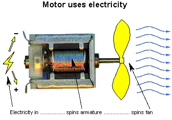
To generate power, various sources are utilized, including diesel engines, gas turbines, and nuclear power plants. Fossil fuels, including natural gas and coal, are burned to create hot gases that go through turbines, which spin the copper armature inside the generator and generate an electric current. In a nuclear power plant, nuclear reactions generate heat that is used to heat water, which then turns into steam and passes through a turbine to produce electricity. In a wind turbine, the wind pushes against the turbine blades, causing the rotor to spin and generating an electric current. In a hydroelectric turbine, flowing or falling water pushes against the turbine blades, causing the rotor to spin and generating an electric current. As the global energy landscape evolves, many experts are re-evaluating the role of nuclear power—learn more in our feature on the future of nuclear energy.


Electricity Generation by Utilities and Non-Utility Power Producers

To meet these immediate demands, utilities and nonutility power producers operate several electric generating units powered by various fuel sources. Renewable fuels, such as water, geothermal, wind, and other renewable energy sources like solar photovoltaics, are used as sources of power, alongside fossil fuels and uranium.


motor


diagram


Fossil Fuel Electricity Generation: Coal, Natural Gas, and Petroleum

Coal was the fuel used to generate the largest share (51.8 percent) of electricity in 2000, with natural gas and petroleum accounting for 16.1 percent and 3 percent, respectively. Steam-electric generating units burn fossil fuels, such as coal, natural gas, and petroleum, to produce steam. This steam is then used to turn a turbine into a generator, producing power. On the other hand, gas turbine generators burn fuels to create hot gases, which also go through a turbine, spinning the copper armature inside the generator and generating an electric current. Diesel engine generators are also used, where the combustion occurs inside the engine's cylinders, which are connected to the generator's shaft. The mechanical energy provided by the turbine drives the generator, which in turn produces energy.


Electricity Generation Trends and the Global Shift Toward Renewables

The production of electrical energy has experienced various eras of significant capacity growth in the United States, Canada, and other countries worldwide. The future of power production is transitioning to a more hybridized generation fleet that relies on a combination of traditional, centralized power production and variable utility-scale and distributed renewable energy sources. Low natural gas prices drive this transition, the rise of renewable and distributed energy sources, and recent Federal and State policies that impact generation. Discover the most common renewable energy sources powering the shift toward a cleaner, more sustainable electricity future.


Enhance your expertise in clean energy with our comprehensive Renewable Energy Grid Integration Training course. Designed for electrical professionals, this course covers the challenges and solutions associated with connecting solar, wind, and other renewable energy sources to the power grid. Stay ahead of industry trends, improve system reliability, and gain valuable skills to support the transition to a sustainable energy future. Enroll today and take the next step in your professional development.


Frequently Asked Questions

How is electricity generated from renewable energy sources?

Electricity is generated from renewable energy sources by converting the energy of the sun, wind, water, or earth into electrical energy. For example, solar photovoltaic panels generate power directly from sunlight, wind turbines to generate electricity from wind energy, and hydroelectric power plants generate power from falling water.


What are the different types of fossil fuels used?

The different types of fossil fuels used include coal, natural gas, and petroleum. Coal is the most commonly used fossil fuel for energy production, followed by natural gas and oil.


What are the advantages and disadvantages of using nuclear power plants for electricity generation?

Advantages of using nuclear power plants include that they produce a large amount of energy with a low amount of fuel, emit less carbon dioxide than fossil fuel power plants, and are not dependent on weather conditions like wind or solar power. Disadvantages include the risks associated with nuclear accidents, the high cost of building and maintaining nuclear power plants, and the long-term storage of nuclear waste.


How do gas turbines work to generate electricity?

Gas turbines burn natural gas or other fuels to heat air, which expands and drives the turbine. Finally, the turbine is connected to a generator that converts the mechanical energy of the turbine into electrical energy.


What is the role of steam turbines in electricity generation?

Steam turbines are commonly used to convert thermal energy from steam into mechanical energy that drives a generator. Steam is produced by burning fossil fuels or using heat from nuclear reactions or geothermal sources. The steam drives the turbine blades, which are connected to the generator to produce electricity.


What are some examples of non-renewable energy sources?

Examples of non-renewable energy sources used for power production include fossil fuels, such as coal, natural gas, and petroleum, as well as nuclear energy.


How is electricity generated and distributed in the United States?

Various power plants, including those powered by fossil fuels, nuclear energy, and renewable energy sources, generate electricity in the United States. Electric power is transported over a complex network of power lines and transformers to homes, businesses, and other consumers through local utility companies. The Federal Energy Regulatory Commission (FERC) and various state regulatory agencies regulate power distribution.


Related Articles


Related News

Wattmeters – Power Measurement

Wattmeters measure electrical power in watts, monitoring energy use in industrial power systems. They provide accurate active power readings for efficiency and load management, utilizing voltage and current measurements to achieve precise results.


What are Wattmeters?

Wattmeters are instruments used to measure electrical power. They:

✅ Measure active electrical power in watts for various applications.

✅ Are used in industrial, commercial, and residential energy monitoring.

✅ Help optimize efficiency, manage loads, and ensure system safety.

A wattmeter measures instantaneous (or short-term) electrical power in watts, while a watthour meter accumulates that power over time and reports energy used (e.g. in kWh). Energy meters and smart meters extend this concept by recording consumption continuously for billing, load analysis, and energy audits.


Working Principle of Wattmeters

Electrical power is calculated using the formula:

P = E × I

Where:

  • P = Power in watts

  • E = Voltage in volts

  • I = Current in amperes

In DC circuits, watts are sometimes expressed as volt-amperes (VA). In AC circuits, wattmeters measure true (or active) power, taking into account the power factor to compensate for phase differences between voltage and current. Unlike reactive power (measured in kvar) or apparent power (measured in kVA), active power is the usable portion that does real work. This relationship is often represented in the power triangle, where vector analysis explains how apparent, reactive, and active power interact.


Construction and Internal Components

A typical wattmeter consists of two main coil assemblies:

  1. Current Coil (CC)

    • Heavy-gauge copper wire with low resistance.

    • Connected in series with the load to carry the circuit current.

  2. Voltage Coil (VC)

    • Fine-gauge wire with high resistance.

    • Connected in parallel with the load to measure voltage.

The electrodynamometer, commonly referred to as a dynamometer wattmeter, is a classic analog device that operates on the principle of a motor. The interaction between the magnetic fields of the current and voltage coils produces a torque proportional to the power, causing the pointer to move over a calibrated scale. Understanding wattmeter principles is a foundation of basic electricity training, helping learners connect theory to practical power measurement.


Figure 1 – Construction of a dynamometer wattmeter showing current and voltage coil arrangement.


Types of Wattmeters

  • Analog/Dynamometer – Durable, reliable, suited for laboratory and field measurements.

  • Digital – Higher accuracy, data logging, and integration with monitoring systems.

  • Clamp-on  – Measure power without breaking the circuit, ideal for quick diagnostics.

  • Specialized  – Designed for RF power, audio power, or other niche applications.

In three-phase systems, wattmeters are often applied in accordance with Blondel’s theorem, which specifies the number of measurement elements required in multi-phase circuits. They are frequently used in conjunction with 3 phase electricity concepts to ensure balanced load distribution and optimal system efficiency.


Fig. 2. Power can be measured with a voltmeter and an ammeter.


Measuring Power in DC and AC Circuits

In DC circuits, power measurement can be as simple as multiplying voltage and current readings from separate meters.

Example:

If a circuit operates at 117 V DC and draws 1 A, the power is:

P = 117 × 1 = 117 W

In AC systems, especially with reactive or distorted loads, a wattmeter is essential because voltage and current may not be in phase. The device automatically accounts for the phase angle, providing accurate true power readings. Advanced digital wattmeters also compensate for harmonic distortion and poor waveform quality, providing more reliable measurements than older analog designs.

By measuring energy transfer in circuits, they also relate to other power measurement instruments such as ammeters, voltmeters, and multimeters, which measure supporting parameters needed for complete electrical analysis. Accurate wattmeter readings are crucial for diagnosing performance issues in 3-phase power networks, where the relationships between voltage and current are critical. By measuring energy transfer in circuits, they help explain fundamental laws of electromagnetism, such as Ampère’s Law, which underpins the interaction between current and magnetic fields.


Fig. 2. Power can be measured with a voltmeter and an ammeter.


Practical Examples and Load Considerations

A household iron may consume 1000 W, drawing 8.55 A at 117 V.

A large heater may draw 2000 W, or 17.1 A, potentially overloading a 15 A breaker.

In industrial settings, watt meters help prevent equipment overloading, reduce downtime, and improve energy efficiency.


Modern Wattmeter Applications

Today’s wattmeters are often part of smart energy monitoring systems that:

  • Track energy consumption over time.

  • Integrate with SCADA and IoT platforms.

  • Enable predictive maintenance through power trend analysis.

  • Support compliance with energy efficiency regulations.


Accuracy, Standards, and Advanced Considerations

Measurement accuracy is a crucial factor in determining wattmeter performance. Devices are often classified by a class of accuracy, with error limits defined by international standards such as IEC, ANSI, or IEEE. Regular calibration and testing procedures ensure watt meters continue to deliver reliable results in both laboratory and field conditions.

Modern digital watt meters feature true RMS measurement, which accurately captures distorted waveforms caused by nonlinear loads. This is especially important in power systems where harmonic distortion is present. In commercial and industrial environments, accurate wattmeter data support energy audits, load analysis, and regulatory compliance, making them indispensable tools for engineers and facility managers. Wattmeter usage is closely linked to the fundamentals of electrical energy, enabling precise monitoring for efficiency and cost control.


Key Advantages of Wattmeters

  • Accurate real-time power measurement.

  • Enhanced energy management and cost savings.

  • Improved system reliability through overload prevention.

  • Compatibility with both AC and DC systems.

Wattmeters remain a vital tool for measuring and managing electrical power. Whether in a simple residential circuit, a commercial energy audit, or a high-tech industrial monitoring system, they ensure that electrical systems run efficiently, safely, and cost-effectively. As technology advances, digital and networked wattmeters continue to expand their role, integrating into smart grids and energy-optimized infrastructures. 


Related Articles


View more

Electricity and Electrical Energy

Electricity powers modern engineering, driving circuits, voltage, current, and AC/DC power systems for transmission, distribution, and control. Engineers analyze resistance, impedance, and frequency, optimize grids, and integrate renewables with transformers, generators, and smart controls.


What Is Electricity?

Electricity is the flow of charge enabling energy conversion, signal transmission, and power control across circuits.

✅ Quantified by voltage (V), current (A), and power (W)

✅ Governed by Ohm's Law, Kirchhoff's Laws, and Maxwell's equations

✅ Transmitted via grids using AC, transformers, and protection


Electricity is a manufactured product. It is not something you pump out of the ground or mine or collect from the sun or wind. For a clear primer on definitions and units, visit what electricity is to ground these ideas.

Electric power is manufactured from a rotating machine that we call an electrical generator. After it is generated, (manufactured) it is then delivered through copper wires to where it is utilized If you want to see how turbines and alternators convert motion into power, explore the electricity generator to understand key components and operation.

Electricity - most people don't understand what it is. They just turn on the light switch or start the appliance or push the button and something works. It's only when there is no electric power available that we start to consider the importance of it in our daily personal and working lives. A step-by-step explanation of fields, voltage, and current is outlined at how electricity works for readers new to the topic.

But the invention of the machine to generate power is right next to the invention of the printing press in the list of major contributions to the advancement of human civilization. For context on pioneers from Faraday to Tesla, review who invented electricity to connect invention with modern grids.

Without it, we would be burning wood and coal to heat our homes and businesses and using oil and candles to light our way in the dark. That is the way it was for humans civilization for countless centuries. Only since the invention of the electric generator have humans been able to advance in every aspect of modern life. In fact, modern living is defined by electric power. This shift from fuels to electrons is traced in the history of electricity to show how infrastructure reshaped society.

We have assembled a series of pages in our web site to help you to understand the business of electricity - how it works and how it is used. To dive deeper into fundamentals before the business aspects, start with electricity: how it works for a concise technical overview.

We hope that you can use this information to better understand the technology and issues behind the manufacturing of electric power. Further reading on thermal, hydro, and renewable pathways is available at how electricity is generated to see how manufacturing methods compare.


Related Articles

View more

Voltage Explained

Voltage is the electric potential difference that drives current through a circuit. It relates to energy conversion, electrical work, power, density, and forms of electricity, explained through principles of conservation and thermodynamics.


What is Voltage?

Voltage is the measure of the electrical potential difference between two points, representing the force that pushes electrons and enables the transfer of energy.

✅ Determines current flow in a circuit

✅ Relates to work, power, and energy conversion

✅ Fundamental to electrical systems and safety


Definition

Voltage (V, EMF, or E) is electrical pressure, a potential force or difference in electrical charge between two points in an electric circuit. Voltage pushes current through a wire, much like water pressure pushes water through a pipe. The level of voltage is proportional to the difference in potential electrical energy between two points. Voltage is measured in volts (V).

  • One volt equals one joule of work per coulomb of charge: V = W/Q

  • Voltage across a resistor follows Ohm’s law: V = I·R

  • Electrical power relates to voltage as P = V·I

A voltage of one volt is required to force one ampere of current through one ohm of resistance. The letter E, which stands for electromotive force (EMF), or V, which stands for volt, is commonly used to represent voltage in formulas. In three-phase systems, voltage plays a critical role in balancing loads and ensuring efficient 3 phase electricity distribution.


Voltage and the Electric Field

Voltage, or potential difference, exists between any two charges that are not equal. Even an uncharged body has a potential difference relative to a charged one. More formally, voltage is linked to the electric field by the relation:

dV/dx = –E

This shows that voltage is the integral of the electric field across a distance. Voltage itself does not flow like current; instead, it exists between two points and provides the force that moves charge when a conductive path is present. A change in voltage across a circuit directly affects the flow of active power and reactive power in modern electrical systems.


DC vs AC Voltage

  • DC Voltage: A steady, unchanging potential difference (like that from a battery).

  • AC Voltage: A time-varying voltage, often sinusoidal in form, alternating between positive and negative values.

AC voltages are described by different measures:

  • Peak voltage: the maximum value reached.

  • RMS (root mean square) voltage: the effective value that produces the same heating effect as DC. For a sinusoidal wave, Vrms = Vpeak/√2.

Visualizing AC voltage as a waveform helps illustrate these differences. In power distribution, nominal voltage ratings are carefully selected to optimize 3 phase power delivery while ensuring electricity safety.


Voltage Sources

  • Ideal sources: Supply a constant voltage regardless of current drawn.

  • Real sources: Contain internal resistance, so voltage drops as load current increases.

This explains why batteries or generators cannot maintain voltage perfectly under heavy load. Voltage sag is a common power quality issue that impacts electrical resistance and the performance of sensitive electrical energy devices.


Measuring Voltage

A voltmeter measures the potential difference between two points. It must be connected across the component, not in series, because voltage is defined between points, not through them. Very small voltages are measured in millivolts and microvolts, while very large ones are expressed in kilovolts and megavolts. To measure voltage accurately, electricians rely on instruments like the voltmeter or multimeter, which are essential for diagnosing electrical circuits.


Voltage, Resistance, and Ohm’s Law

Electrical resistance (R) is the opposition to the flow of electrons (current). It can be compared to friction that slows motion. Resistance is measured in ohms (Ω).

Resistance arises partly because atoms resist losing electrons to the positive nucleus, and partly due to collisions between moving electrons and atoms. This resistance produces heat, which is why wires warm up when current flows. Heating elements and lamp filaments operate on this principle, as their high resistance converts electrical energy into light and heat.

Every electrical component has some resistance, and resistance changes electrical energy into other forms such as heat, light, or motion.

An ohmmeter is used to measure resistance when no current is flowing. Most multimeters include an ohmmeter function powered by an internal battery. For this reason, ohmmeters should never be connected to live circuits.

Ohm’s Law ties resistance directly to voltage: V = I·R. The higher the resistance, the greater the voltage required to drive a given current. The relationship between voltage, current, and resistance is the foundation of Ohm’s Law, which underpins all basic electricity concepts.


Safety Considerations

Voltage is directly tied to safety in electrical systems. High voltages can break down insulation, ionize air, and cause arcing or shock hazards.

  • Breakdown voltage: The point at which insulation fails and current flows uncontrollably.

  • Dielectric strength: A material’s maximum withstand voltage before breakdown.

  • Ratings: All equipment is equipped with voltage ratings to ensure safe operation.

Understanding these factors is critical for designing and maintaining safe electrical systems.


Worked Examples

  1. Simple resistor: A 2 A current flows through a 5 Ω resistor. Voltage = I·R = 2 × 5 = 10 V.

  2. Power relation: A device consumes 100 W at 5 A. Voltage = P/I = 100 ÷ 5 = 20 V.

  3. AC RMS: If Vpeak = 170 V, then Vrms = 170/√2 ≈ 120 V, the common household supply.


History and Applications

The unit “volt” is named after Alessandro Volta, the Italian scientist who pioneered the first chemical battery, the voltaic pile. His work established the foundation of the modern history of electricity.

Today, voltage underpins every electrical system, from the smallest microchip to the largest power grid. It enables energy transfer, communication, motion, and the transmission of light.


Frequently Asked Questions


Can voltage exist without current?

Yes. Voltage can be present even if no current flows. A battery not connected to a circuit still has a measurable voltage.


What’s the RMS voltage?

It is the effective value of an alternating voltage that produces the same heating effect as a direct voltage.


What is safe voltage?

Safe limits depend on the context, but typically 50 V or less is considered a threshold below which the risk of shock is reduced, although not eliminated.


Related Articles


View more

Power System Analysis Explained

Power System Analysis enables load flow studies, fault calculations, stability assessment, state estimation, and contingency analysis for grids, integrating SCADA data, protection coordination, and reliability planning to optimize transmission, distribution, and generation performance.


What Is Power System Analysis?

Power System Analysis models grid behavior to ensure stability, reliability, efficiency, and secure operation.

✅ Load flow, short-circuit, and transient stability studies

✅ State estimation, SCADA integration, and contingency analysis

✅ Protection coordination, reliability assessment, and optimization


Power system analysis (PSA) is an essential electrical system component. It helps to ensure that the electrical system operates efficiently, reliably, and safely. Power flow analysis, fault study, stability investigation, renewable energy integration, grid modernization, and optimization techniques are all essential concepts in PSA. As our society continues to rely heavily on electricity, PSA will remain a vital tool for ensuring the stability and reliability of the electrical system. For foundational context on how electricity underpins these studies, see this primer on what electricity is and how it behaves.

One of the critical concepts in PSA is power system modelling. Modelling is creating a mathematical model of the electrical system. This model includes all the system components, such as generators, transformers, transmission lines, and distribution networks. Modelling is essential as it provides a detailed understanding of the system's workings. Engineers commonly begin by drafting a single-line diagram to visualize component interconnections and power paths.

Another critical concept in PSA is power flow investigation, also known as load flow investigation. Power flow analysis calculates the electrical system's voltages, currents, and power flows under steady-state conditions. A power flow study helps determine whether the electrical system can deliver electricity to all the loads without overloading any system component. The results of the power flow investigation are used to plan the system's expansion and ensure that it operates efficiently and reliably. In practice, load-flow outputs are interpreted within the broader context of electric power systems to validate voltage profiles and thermal limits.

Fault study is another crucial component of PSA. A fault study is a process of analyzing the system's behaviour during a fault condition. This needs a short circuit analysis. A fault is abnormal when the system has a short or open circuit. A fault study helps to determine the fault's cause and develop strategies to prevent or mitigate the effects of faults in the future.

Stability investigation is also an important aspect of PSA. Stability investigation is the process of analyzing the system's behaviour under dynamic conditions. For example, the system is subject to dynamic disturbances, such as sudden load or generator output changes, which can cause instability. Stability investigation helps ensure the system can withstand these disturbances and operate reliably.

The transient investigation is another key concept in PSA. The transient study analyzes the electrical system's behaviour during transient conditions, such as switching operations or lightning strikes. A brief investigation helps ensure the system can withstand these transient conditions and operate reliably.

Renewable energy integration is an emerging concept in PSA. As more renewable energy sources, such as wind and solar power, are integrated into the energy system, PSA becomes increasingly essential to ensure the stability and reliability of the electrical system. Understanding how generation mixes are formed benefits from a primer on how electricity is generated across thermal, hydro, and renewable technologies.

Grid modernization is also a crucial aspect of PSA. As the system ages, it becomes increasingly important to modernize the grid to ensure that it can meet the demands of modern society. Therefore, PSA is used to develop strategies to modernize the grid and ensure it operates efficiently, reliably, and safely. Many modernization roadmaps align with the evolving architecture of the electricity grid as utilities adopt automation, advanced metering, and distributed resources.

Finally, protection coordination and optimization techniques are essential components of PSA. Protection coordination involves developing strategies to protect the electrical system from faults and other abnormal conditions. Optimization techniques involve developing strategies to optimize the system's operation and ensure it operates efficiently and reliably. Because reactive power and losses affect dispatch, monitoring and improving power factor can materially enhance system efficiency.


What is power system analysis, and why is it important?

PSA analyzes the electrical system to ensure it operates efficiently, reliably, and safely. Therefore, it is crucial to identify potential problems before they occur and develop strategies to prevent or mitigate the effects of these problems. In addition, PSA is important because it helps ensure that the electrical system can meet the demands of modern society, which relies heavily on electricity.


How is power flow analysis performed?

Power flow analysis, or load flow analysis, is performed using a mathematical model. The model includes all the power system components, such as generators, transformers, transmission lines, and distribution networks. A power flow study calculates the electrical system's voltages, currents, and power flows under steady-state conditions. The results of the power flow investigation are used to plan the electrical system's expansion and ensure that it operates efficiently and reliably. These studies also quantify reactive power behavior, making concepts like what power factor is directly applicable to planning and operations.


What is fault analysis, and how is it used?

Fault analysis is analyzing the system's behaviour during a fault condition. A fault is abnormal when the system has a short or open circuit. A fault study is used to determine the fault's cause and develop strategies to prevent or mitigate the effects of faults in the future. Fault analysis is crucial in ensuring the safety and reliability of the electrical system.


What are the different stability study techniques used?

Several stability investigation techniques are used in PSA to measure transient, small-signal, and voltage stability. Transient stability is used to analyze the behaviour of the distribution under dynamic conditions, such as sudden changes in load or generator output. Small-signal stability measurement analyzes the system's behaviour under small disturbances. Finally, voltage stability measurement is used to analyze the system's behaviour under steady-state conditions and determine the system's voltage limits.


How does renewable energy integration affect power system analysis?

Renewable energy integration is an emerging concept in PSA. As more renewable energy sources, such as wind and solar power, are integrated into the electrical system, PSA becomes increasingly essential to ensure the stability and reliability of the system. Renewable energy sources are intermittent, which can cause fluctuations in the system. PSA is used to develop strategies to integrate renewable energy sources into the system while ensuring its stability and reliability.


What are the challenges of grid modernization, and how does power system analysis help overcome them?

Grid modernization is a crucial aspect of PSA. As the system ages, it becomes increasingly important to modernize the grid to ensure that it can meet the demands of modern society. Grid modernization involves upgrading the system to incorporate new technologies, such as smart grid technologies and renewable energy sources. The challenges of grid modernization include the need for new infrastructure, the integration of new technologies, and new regulatory frameworks. PSA is used to develop strategies to overcome these challenges and to ensure that the electrical system operates efficiently, reliably, and safely.


How can optimization techniques improve system efficiency and reliability in power system analysis?

Optimization techniques can be used in PSA to improve system efficiency and reliability. These techniques involve developing strategies to optimize the system's operation and ensure it operates efficiently and reliably. For example, optimization techniques can determine the optimal generation and transmission of power, improve load forecasting, and develop strategies to reduce energy consumption. PSA is crucial in developing and implementing these optimization techniques, which help improve the electrical system's overall efficiency and reliability, leading to a more sustainable and cost-effective electrical power system.


Related Articles

View more

Understanding Current

Current is the flow of electric charge in circuits, defined by amperage, driven by voltage, limited by resistance, described by Ohm’s law, and fundamental to AC/DC power systems, loads, conductors, and electronic components.


What Is Current?

Current is charge flow in a circuit, measured in amperes and governed by voltage and resistance.

✅ Measured in amperes; sensed with ammeters and shunts

✅ Defined by Ohm’s law: I = V/R in linear resistive circuits

✅ AC alternates; DC is steady; sets power transfer P = V*I


Current is best described as a flow of charge or that the charge is moving. Electrons in motion make up an electric current. This electric current is usually referred to as “current” or “current flow,” no matter how many electrons are moving. Current is a measurement of a rate at which a charge flows through some region of space or a conductor. The moving charges are the free electrons found in conductors, such as copper, silver, aluminum, and gold. The term “free electron” describes a condition in some atoms where the outer electrons are loosely bound to their parent atom. These loosely bound electrons can be easily motivated to move in a given direction when an external source, such as a battery, is applied to the circuit. These electrons are attracted to the positive terminal of the battery, while the negative terminal is the source of the electrons. The greater amount of charge moving through the conductor in a given amount of time translates into a current. For a concise overview of how moving charges create practical circuits, see this guide to current electricity for additional context.


The System International unit for current is the Ampere (A), where


That is, 1 ampere (A) of current is equivalent to 1 coulomb (C) of charge passing through a conductor in 1 second(s). One coulomb of charge equals 6.28 billion billion electrons. The symbol used to indicate current in formulas or on schematics is the capital letter “I.” To explore the formal definition, standards, and measurement practices, consult this explanation of the ampere for deeper detail.

When current flow is one direction, it is called direct current (DC). Later in the text, we will discuss the form of current that periodically oscillates back and forth within the circuit. The present discussion will only be concerned with the use of direct current. If you are working with batteries or electronic devices, you will encounter direct current (DC) in most basic circuits.

The velocity of the charge is actually an average velocity and is called drift velocity. To understand the idea of drift velocity, think of a conductor in which the charge carriers are free electrons. These electrons are always in a state of random motion similar to that of gas molecules. When a voltage is applied across the conductor, an electromotive force creates an electric field within the conductor and a current is established. The electrons do not move in a straight direction but undergo repeated collisions with other nearby atoms. These collisions usually knock other free electrons from their atoms, and these electrons move on toward the positive end of the conductor with an average velocity called the drift velocity, which is relatively a slow speed. To understand the nearly instantaneous speed of the effect of the current, it is helpful to visualize a long tube filled with steel balls as shown in Figure 10-37. It can be seen that a ball introduced in one end of the tube, which represents the conductor, will immediately cause a ball to be emitted at the opposite end of the tube. Thus, electric current can be viewed as instantaneous, even though it is the result of a relatively slow drift of electrons. For foundational concepts that connect drift velocity with circuit behavior, review this basic electricity primer to reinforce the fundamentals.

Current is also a physical quantity that can be measured and expressed numerically in amperes. Electric current can be compared to the flow of water in a pipe. It is measureda at the rate in which a charge flows past a certain point on a circuit. Current in a circuit can be measured if the quantity of charge "Q" passing through a cross section of a wire in a time "t" (time) can be measured. The current is simply the ratio of the quantity of charge and time. Understanding current and charge flow also clarifies how circuits deliver electrical energy to perform useful work.


Electrical current is essentially an electric charge in motion. It can take either the form of a sudden discharge of static electricity, such as a lightning bolt or a spark between your finger and a ground light switch plate. More commonly, though, when we speak of current, we mean the more controlled form of electricity from generators, batteries, solar cells or fuel cells.  A helpful overview of static, current, and related phenomena is available in this summary of electricity types for quick reference.

We can think of the flow of electrons in a wire as the flow of water in a pipe, except in this case, the pipe of water is always full. If the valve on the pipe is opened at one end to let water into the pipe, one doesn't have to wait for that water to make its way all the way to the other end of the pipe. We get water out the other end almost instantaneously because the incoming water pushes the water that's already in the pipe toward the end. This is what happens in the case of electrical current in a wire. The conduction electrons are already present in the wire; we just need to start pushing electrons in one end, and they start flowing at the other end instantly. In household power systems, that push on conduction electrons alternates in direction as alternating current (AC) drives the flow with a time-varying voltage.


Current Formula

Current is rate of flow of negatively-charged particles, called electrons, through a predetermined cross-sectional area in a conductor.

 Essentially, flow of electrons in an electric circuit leads to the establishment of current.

q = relatively charged electrons (C)

t = Time

Amp = C/sec

Often measured in milliamps, mA


Related Articles

View more

Nominal Voltage and AC and DC Standards

Nominal voltage is the standard voltage level assigned to electrical equipment or systems for identification. It helps ensure compatibility, performance, and safety across devices without indicating actual operating voltage, which may vary slightly.


What is Nominal Voltage?

Nominal voltage refers to the labelled voltage value of an electrical system or device.

✅ Represents standard system voltage, not an  exact measurement

✅ Helps match equipment compatibility and safety standards

✅ Common in power distribution, residential, and industrial systems


Nominal voltage (NV) is a vital aspect of electrical systems, serving as a reference point for designing, manufacturing, and testing equipment. Additionally, it affects the performance, efficiency, and safety of electrical systems, with voltage regulation ensuring that voltage levels (V) remain within acceptable tolerances. Understanding the differences between nominal voltage, operating voltage (OV), and rated voltage (RV) is crucial for professionals and enthusiasts to ensure the effective operation and maintenance of electrical systems. To better understand how nominal voltage fits within broader system design, see our comprehensive overview on voltage.

It is vital to understand the definition and importance of nominal voltage in electrical systems. NV refers to the standard voltage value assigned to an electrical system, typically the voltage that electrical equipment is designed to operate under normal conditions. This value is crucial because it serves as a reference point for designing, manufacturing, and testing electrical equipment to ensure satisfactory performance. Maintaining voltage stability is essential—learn how voltage drop impacts performance and how to accurately calculate it.

Determining nominal voltage for electrical systems involves considering factors such as the type of equipment being used, the overall power requirements, and the voltage standards set by industry organizations. In some cases, the NV is set by the equipment manufacturer, while in others, it depends on the power grid's Voltage levels. Standard nominal voltages have been established to streamline equipment design and manufacturing processes. Use our voltage drop calculator to determine how wiring distance and load affect nominal voltage in real applications.

The terms NV, OV, and RV often appear in discussions about electrical systems. While they may seem interchangeable, each has a distinct meaning. As previously mentioned, nominal voltage is the standard voltage value designated for an electrical system. On the other hand, OV is the actual voltage at which equipment functions during operation. Similar to nominal voltage, RV refers to the maximum voltage at which equipment can operate continuously without sustaining damage. See how voltage regulators are used to maintain nominal levels and protect sensitive equipment.

Nominal voltage has a direct impact on the performance of electrical systems. Equipment designed for specific NVs operates safely within a particular voltage range. Operating outside this range can result in equipment damage, decreased efficiency, and even electrical fires. Therefore, it is essential to maintain the voltage levels as close as possible to the NV. Our guide to what is voltage explains the differences between nominal, operating, and actual voltage in power systems.

Electrical systems worldwide adhere to common national voltage (NV) standards for alternating (AC) and direct (DC) systems. For AC systems, NV  ranges include 110V, 220V, and 380V, while DC systems typically have NVs of 12V, 24V, or 48V. These standardized voltage levels enable the compatibility and interoperability of electrical equipment across various regions and industries. Learn how wattmeters and voltmeter tools help monitor nominal and real-time voltage values in field diagnostics.

Voltage regulation plays a critical role in controlling an electrical system's output voltage to ensure it remains within the acceptable voltage tolerance. Voltage regulation can be achieved through various means, including transformers, voltage regulators, and software algorithms in modern power systems. By maintaining NV, the electrical system The voltages more efficiently and safely, ensuring the longevity of the equipment.

The voltage tolerance is the range of voltage deviation from the nominal voltage value within which equipment can still operate effectively and safely. Different electrical systems have different voltage tolerances depending on the nature of the equipment and its intended use. For instance, a residential electrical system may have a voltage tolerance of +/- 5%, while an industrial system might tolerate a deviation of +/- 10%. Maintaining the acceptable V tolerance is crucial for the satisfactory operation of electrical equipment.


Nominal Voltage (NV) vs Operating Voltage (OV)

Nominal voltage and OV are two related yet distinct concepts in electrical engineering systems. Understanding the different essentials to ensure electrical systems' safe and efficient operation.

Nominal voltage refers to the standard or reference voltage level assigned to an electrical system, circuit, or device. It is the ideal voltage at which the equipment is designed to operate under normal conditions. NV is a baseline value that allows manufacturers, engineers, and technicians to design, test, and rate electrical equipment consistently.

Conversely, OV is the actual voltage level at which a particular electrical system, circuit, or device is functioning during real-time operation. Unlike nominal voltage, OV can fluctuate due to factors such as load changes, temperature variations, and power supply issues. Although electrical equipment is designed to operate optimally within a specified voltage range around the nominal voltage, slight variations in the operating V are often unavoidable.

In essence, NV serves as the benchmark or target voltage level, while OV reflects the real-world voltage conditions experienced by the electrical equipment. To ensure the efficient and safe operation of electrical systems, it is crucial to maintain the OV as close as possible to the NV. When the operating voltage falls within the acceptable voltage tolerance range, electrical equipment can function efficiently and safely without the risk of damage or performance degradation. Discover how alternating current systems rely on standardized nominal voltages like 120V or 240V for safe and consistent operation.


Nominal Voltage (NV) vs Rated Voltage (RV)

Nominal voltage and RV are related terms in electrical engineering but have distinct meanings and implications. Understanding the difference between the two is crucial for designing, operating, and maintaining electrical systems and devices properly. Differences between high voltage, medium voltage, and low voltage categories are based on standardized nominal values used in system classification.

It refers to the standard or reference voltage level assigned to an electrical system, circuit, or device. It is the ideal voltage at which the equipment is designed to operate under normal conditions. NV serves as a baseline value that enables manufacturers, engineers, and technicians to design, test, and rate electrical equipment consistently across various industries and applications.

On the other hand, RV is the maximum voltage at which an electrical device or component can operate continuously without incurring damage or experiencing a significant reduction in performance. RV is a critical parameter to ensure electrical equipment's safe and efficient functioning. Operating an electrical device within its RV range prevents excessive stress on the device, thereby reducing the risk of failure or shortened lifespan. Understanding the concept of electrical resistance is key to managing voltage drop and maintaining nominal voltage across circuits.

Nominal voltage is the target or reference Voltage level for the design and operation of electrical systems. In contrast, RV defines the maximum allowable Voltage for the continuous operation of electrical equipment. To ensure the efficient and safe performance of electrical systems, it is essential to maintain the operating voltage within the acceptable voltage tolerance range around the nominal voltage and not exceed the RV.  The relationship between power factor and nominal voltage affects system efficiency, especially in industrial electrical networks.


Related Articles


View more

Sign Up for Electricity Forum’s Newsletter

Stay informed with our FREE Newsletter — get the latest news, breakthrough technologies, and expert insights, delivered straight to your inbox.

Electricity Today T&D Magazine Subscribe for FREE

Stay informed with the latest T&D policies and technologies.
  • Timely insights from industry experts
  • Practical solutions T&D engineers
  • Free access to every issue

Live Online & In-person Group Training

Advantages To Instructor-Led Training – Instructor-Led Course, Customized Training, Multiple Locations, Economical, CEU Credits, Course Discounts.

Request For Quotation

Whether you would prefer Live Online or In-Person instruction, our electrical training courses can be tailored to meet your company's specific requirements and delivered to your employees in one location or at various locations.