Faraday's Law Explained

By R.W. Hurst, Editor


Faraday’s Law describes electromagnetic induction, where changing magnetic fields generate electricity. Discovered in 1831 by Michael Faraday, it revealed how magnetism produces electric current and became the foundation of modern electrical science.


What is Faraday’s Law?

Faraday's Law is a fundamental principle of electromagnetism describing how a changing magnetic field induces an electromotive force (emf) in a conductor. The law: 

✅ Explains electromagnetic induction and induced current

✅ Is essential for transformers, generators, and electric motors

✅ Is the foundation of modern physics and electrical engineering

For a deeper look at the mathematics, mechanisms, and engineering uses, see our detailed guide on Faraday’s Law of Induction."


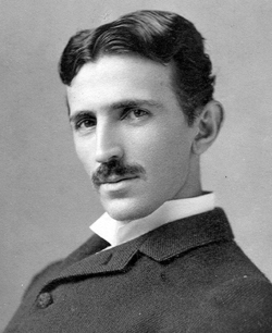
Michael Faraday, the Inventor of Faraday’s Law

In 1831, Michael Faraday performed experiments with coils of wire, magnets, and galvanometers. He observed that when a magnet was moved through a coil, or when the magnetic field around the coil was changed, a current was generated.

Faraday’s Law proved that electricity could be produced directly from magnetism — a revolutionary concept at the time. Faraday’s experiments were deceptively simple but profoundly important, showing that energy could be converted from one form (mechanical motion of the magnet) into another (electric current). 


Theoretical Context

Faraday’s Law provided one of the first clear demonstrations that electricity and magnetism are not separate forces but part of the same phenomenon. This insight was later formalized by James Clerk Maxwell, whose Maxwell’s equations mathematically unified electromagnetism.

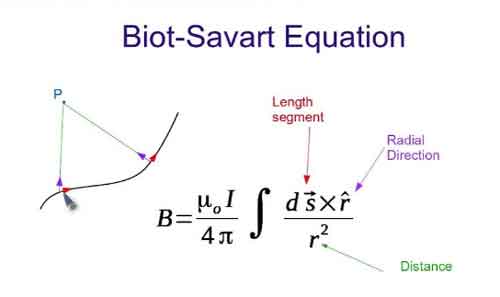
Alongside Ampère’s Law and the Biot–Savart Law, Faraday’s Law gave scientists a new framework to describe the invisible forces of nature. It also introduced the idea of fields, regions of influence surrounding magnets and electrical charges, which became central to modern physics. Read our article titled: Who Invented Electricity for more information about the foundation of electricity.


Understanding Electromagnetic Induction

Faraday’s Law showed that induction can occur in several ways:

  • By moving a conductor through a magnetic field

  • By changing the strength of a magnetic field

  • By altering the orientation or size of the conductor’s loop in the field

In each case, the result is the same: a changing magnetic flux produces an EMF. The direction of the induced current is explained by Lenz’s Law, which states that the induced current always opposes the change that created it, ensuring energy conservation.

The principle of electromagnetic induction is the basis for the operation of various electrical devices, including:

  • Generators: These devices convert mechanical energy into electrical energy by rotating a coil within a magnetic field, causing the magnetic flux to change and inducing an EMF in the coil.

  • Transformers: Transformers work on the principle of mutual induction, where a changing current in the primary coil produces a varying magnetic field, which in turn induces an EMF in the secondary coil.

  • Induction motors: In these motors, a changing magnetic field is created by the stator, inducing an EMF in the rotor conductors, which generates a current that interacts with the magnetic field to produce torque and drive the motor.


Coils, Flux, and Electrodynamics

Faraday’s induction experiments showed that the induced voltage in a coil is equal to the rate of change of magnetic flux through it. This relationship depends on several factors, including the magnetic field strength, the loop area, and the number of turns in the coil. In fact, the induced EMF is proportional to the rate at which a coil of wire cuts across magnetic field lines, meaning that more turns in the coil increase the overall flux linkage.

From the perspective of electrodynamics, this effect illustrates how charges respond to forces within a conductor. The Lorentz force explains why electrons move when exposed to a changing field, while a time-varying field generates a non-conservative electric field that sustains induction. These principles are embedded in the Maxwell–Faraday equation, which extends Faraday’s insight into the framework of Maxwell’s equations.

Faraday also noted that induction is not limited to mutual coupling between separate coils. The principle of self-induction arises when a coil’s own changing current produces an induced EMF opposing the original change. This phenomenon became central to the design of inductors and transformers.

Ultimately, the legacy of Faraday’s Law extends to our understanding of electromagnetic waves. By linking induction with Maxwell’s field theory, Faraday’s Law explains how time-varying fields generate waves that propagate through space — a concept that underpins modern communications and physics.


Why Faraday’s Law Mattered

At the time of its discovery, electricity was known mainly from batteries and static experiments. Faraday’s Law proved that electricity could be generated in continuous and controlled ways. This breakthrough opened the door to inventions that would transform society, from power generation to communication technologies.


Everyday Applications of Faraday’s Law

The importance of Faraday’s Law extends far beyond the laboratory. It forms the basis of countless technologies, including:

  • Electric generators – converting mechanical energy into electrical power.

  • Transformers – enabling efficient power transmission over long distances.

  • Induction motors – powering everything from industrial machines to household appliances.

  • Wireless charging systems – transferring energy without physical connections.

  • Magnetic storage and security – used in swipe cards and sensors.

  • Induction heating and cooktops – converting magnetic energy into heat for practical use.

  • Eddy current braking – providing non-contact braking in trains, amusement rides, and industrial systems by inducing currents that resist motion.

  • Inductors in circuits – storing energy in magnetic fields and controlling current in electrical systems.

  • Wireless energy transfer in EVs – enabling electric vehicles to charge without plugs using electromagnetic induction.

These applications show how Faraday’s 19th-century experiments continue to power the 21st-century world.


Faraday’s Legacy

Faraday’s Law was not just a scientific milestone but also a turning point for technology and industry. Without his insights, there would be no electric power grids, no telecommunications as we know them, and no modern electronics.

The law also highlighted an important principle: that simple experiments can lead to world-changing insights. With little formal education, Faraday reshaped science and technology, showing that careful observation and curiosity could unlock nature’s secrets.

Faraday’s Law remains one of the most important discoveries in physics. By revealing that changing magnetic fields could create electricity, it provided the foundation for modern electrical engineering, industrial power systems, and everyday devices.

Faraday’s Law stands as a reminder that the forces of nature — magnetism, electricity, and motion — are deeply interconnected. Faraday’s insight into electromagnetic induction continues to shape the modern world, demonstrating that a discovery made nearly two centuries ago remains a vital force in our lives today.


Frequently Asked Questions


What did Faraday’s Law prove?

Faraday’s experiments with coils and magnets in 1831 proved that a changing magnetic field can induce an electromotive force (EMF) in a conductor. This showed that electricity can be generated from magnetism, a discovery that revolutionized science and technology.


Why is Faraday’s Law important today?

Faraday’s Law is the foundation of electrical power generation and transmission. It explains how generators, transformers, and induction motors work, making it essential to modern energy systems, communication technologies, and countless everyday devices.


How does Faraday’s Law relate to Maxwell’s equations?

Faraday’s Law was later formalized in Maxwell’s equations as the Maxwell–Faraday equation, which shows that a changing magnetic field produces an electric field. This unification confirmed that electricity and magnetism are two aspects of the same force.

Related News

Thevenin's Theorem

Thevenin’s Theorem simplifies complex linear circuits into a single voltage source and series resistance, making circuit analysis easier for engineers. It helps calculate current, load behavior, and equivalent resistance in practical electrical systems.


What is Thevenin’s Theorem?

Thevenin’s Theorem is a method in circuit analysis that reduces any linear electrical network to an equivalent circuit with a voltage source (Vth) in series with a resistance (Rth).

✅ Simplifies circuit analysis for engineers and students

✅ Calculates load current and voltage with accuracy

✅ Models equivalent resistance for real-world applications

Thevenin’s Theorem allows any linear, two-terminal circuit to be represented by a single voltage source in series with a resistance.

  • Reduces complex circuits to a simple equivalent consisting of a voltage source and a resistor

  • Makes analyzing load response and network behavior straightforward, saving time and effort

  • Widely used for calculating current, voltage, or power across loads in electrical networks

To fully grasp why Thevenin’s Theorem matters, it helps to revisit the principles of basic electricity, where voltage, current, and resistance form the foundation of all circuit analysis.


Understanding Thevenin’s Theorem

Thevenin’s Theorem is a cornerstone of basic electrical engineering and circuit analysis. First introduced by French engineer Léon Charles Thévenin in the late 19th century, the theorem allows engineers and students alike to simplify a complex electrical network to a single voltage source (known as the Thevenin voltage, Vth) in series with a single resistor (known as the Thevenin resistance, Rth). This is particularly useful when analyzing how a circuit will behave when connected to different loads. Concepts such as Ohm’s Law and electrical resistance work in conjunction with Thevenin’s method, ensuring accurate load and network calculations.

Thevenin’s Theorem states that any linear electrical network can be simplified to an equivalent circuit consisting of a single voltage source in series with a resistance. By removing the load resistance, engineers can calculate the equivalent circuit voltage at the terminals, which represents how the circuit will behave when reconnected. This approach replaces multiple components and ideal voltage sources with one simplified model, making circuit analysis more efficient while preserving accuracy in predicting load behavior.


How Thevenin’s Theorem Works

According to Thevenin’s Theorem, no matter how complicated a linear circuit may be, with multiple sources and resistors, it can be replaced by an equivalent Thevenin circuit. This greatly simplifies the process when you’re only interested in the voltage, current, or power delivered to a specific part of the circuit. The steps typically followed when using Thevenin’s Theorem are:

  1. Identify the portion of the circuit for which you want to find the Thevenin equivalent (usually across two terminals where a load is or will be connected).

  2. Remove the load resistor and determine the open-circuit voltage across the terminals. This voltage is the Thevenin voltage (Vth).

  3. Calculate the Thevenin resistance (Rth) by deactivating all independent voltage sources (replace them with short circuits) and current sources (replace them with open circuits), then determining the resistance viewed from the terminals.

  4. Redraw the circuit as a single voltage source Vth in series with resistance Rth, with the load resistor reconnected.


Why Use Thevenin’s Theorem?

There are several reasons why Thevenin’s Theorem is so widely used in both academic and practical electrical engineering:

  • Simplification – Instead of solving a complex network repeatedly each time the load changes, engineers can just reconnect different loads to the Thevenin equivalent, saving time and reducing the potential for error.

  • Insight – By reducing a circuit to its essential characteristics, it’s easier to understand how changes will affect load voltage, current, or power.

  • Foundation for Further Analysis – Thevenin’s Theorem forms the basis for other network analysis techniques, such as Norton's Theorem, and is fundamental to understanding more advanced topics like maximum power transfer.


Example Application

Imagine a scenario where you need to analyze a circuit with multiple resistors and voltage sources connected in series, with a load resistor at the end. Without Thevenin’s Theorem, calculating the voltage across or current through the load each time you change its resistance would require solving complicated sets of equations. Thevenin’s Theorem allows you to do all the hard work once, finding Vth and Rth, and then quickly see how the load responds to different values.

Illustrative Case: A power supply circuit needs to be tested for its response to varying loads. Instead of recalculating the entire network for each load, the Thevenin equivalent makes these calculations swift and efficient. A deeper look at capacitance and inductance shows how energy storage elements influence circuit behavior when simplified through equivalent models.


Limitations and Conditions

While powerful, Thevenin’s Theorem has limitations:

  • It only applies to linear circuits, those with resistors, sources, and linear dependent sources.

  • It cannot directly simplify circuits containing nonlinear elements such as diodes or transistors in their nonlinear regions.

  • The theorem is most useful for “two-terminal” or “port” analysis; it doesn’t help as much with multiple output terminals simultaneously, though extensions exist.


Connections to Broader Electrical Concepts

Thevenin’s Theorem is closely related to other concepts, such as Norton’s Theorem, which prescribes an equivalent current source and parallel resistance. Both theorems are widely applied in real-world scenarios, including power distribution, signal analysis, and the design of electronic circuits. For example, it's relevant when considering how hydro rates impact load distribution in utility networks.

Thevenin’s Theorem is more than just a trick for simplifying homework—it is a core analytical tool that forms the backbone of practical circuit analysis. Whether you are a student learning circuit theory or an engineer designing power systems, understanding and applying Thevenin’s Theorem is essential.  Understanding current flow and the role of a conductor of electricity provides practical insight into why reducing networks to simple equivalents makes engineering analysis more efficient.


Related Articles


View more

Electricity Terms Explained

Electricity terms explain voltage, current, resistance, impedance, power factor, frequency, AC/DC, circuits, transformers, and load. Master key definitions to analyze systems, size conductors, mitigate harmonics, and ensure safety compliance.


What Are Electricity Terms?

Standardized definitions for voltage, current, resistance, impedance, and power factor used in electrical engineering.

✅ Define units, symbols, and formulas per IEEE/IEC standards

✅ Clarify AC/DC behavior, phasors, impedance, and power factor

✅ Aid circuit analysis, sizing conductors, and safety compliance


Here are the top 50 commonly used electricity terms that are essential for understanding electrical systems, devices, and concepts: For a broader glossary with context and examples, see the curated list at Electrical Terms by Electricity Forum for deeper reference.

Voltage (V) – The electrical potential difference between two points in a circuit. Understanding how potential difference relates to the nature of electricity is clarified in this overview of what electricity is and how it behaves.

Current (I) – The flow of electric charge, measured in amperes (A). A concise explanation of electricity as a physical phenomenon is given in this definition of electricity for foundational understanding.

Resistance (R) – Opposition to current flow, measured in ohms (Ω).

Power (P) – The rate of doing work or transferring energy, measured in watts (W).

Ohm's Law – The relationship between voltage, current, and resistance. For a step-by-step refresher on the relationships among voltage, current, and resistance, explore this basic electricity guide to connect theory with practical examples.

Alternating Current (AC) – Electric current that reverses direction periodically.

Direct Current (DC) – Electric current that flows in one direction only. For a side-by-side comparison of waveform behavior, applications, and conversion methods, review the differences between AC and DC to strengthen conceptual understanding.

Frequency (f) – The number of cycles per second in AC, measured in hertz (Hz).

Impedance (Z) – The total opposition to current flow in an AC circuit, combining resistance and reactance, measured in ohms.

Capacitance (C) – The ability to store electrical energy in an electric field, measured in farads (F).

Inductance (L) – The ability of a conductor to induce a voltage when current changes, measured in henries (H).

Power Factor (PF) – The ratio of real power to apparent power, indicating the efficiency of a system.

Real Power (P) – The actual power consumed to perform work, measured in watts.

Apparent Power (S) – The total power in a system, combining real and reactive power, measured in volt-amperes (VA).

Reactive Power (Q) – Power in AC circuits that does not perform useful work, measured in volt-amperes reactive (VAR).

Load – The device or equipment that consumes electrical power.

Short Circuit – An abnormal connection between two points in a circuit, causing excessive current flow. To ground this topic in fundamentals, revisit what an electrical circuit is before examining fault conditions.

Overload – A condition where a circuit or device exceeds its rated current capacity.

Circuit Breaker – A protective device that interrupts the flow of current when an overload or short circuit occurs.

Fuse – A protective device that melts to break the circuit when excessive current flows.

Grounding (Earthing) – Connecting parts of an electrical system to the Earth to ensure safety.

Transformer – A device that transfers electrical energy between two or more circuits through electromagnetic induction.

Conductor – A material that allows the flow of electrical current, typically copper or aluminum.

Insulator – A material that resists the flow of electric current, such as rubber or plastic.

Phase – The distribution of alternating current electricity into separate waveforms, often used in three-phase power systems.

Watt (W) – The unit of power, equivalent to one joule per second.

Kilowatt (kW) – A unit of power equal to 1,000 watts.

Megawatt (MW) – A unit of power equal to 1 million watts.

Voltage Drop – The reduction in voltage across a component or conductor in an electrical circuit.

Arc Flash – A dangerous condition associated with the release of energy caused by an electric arc.

Resistor – A component that opposes the flow of current, used to control voltage and current in circuits.

Diode – A semiconductor device that allows current to flow in one direction only.

Rectifier – A device that converts AC to DC.

Inverter – A device that converts DC to AC.

Contactor – An electrically controlled switch used to control a power circuit.

Relay – A switch operated by an electromagnet, used for controlling circuits.

Switchgear – Equipment used to switch, control, and protect electrical circuits.

Distribution System – The system of wires and equipment that delivers electricity from substations to consumers.

Neutral – A conductor that carries current back to the source in an electrical system.

Busbar – A conductor used to distribute power from one source to multiple circuits.

Overcurrent Protection – Devices like fuses and circuit breakers designed to protect circuits from excessive current.

Phase Angle – The angular displacement between voltage and current waveforms in AC circuits.

Power Supply – A device that provides the necessary electrical power to a circuit or device.

Generator – A device that converts mechanical energy into electrical energy. This ties directly to how electrical energy is produced, transferred, and ultimately consumed.

Motor – A device that converts electrical energy into mechanical energy.

Frequency Converter – A device that changes the frequency of AC power.

Power Grid – A network of transmission lines, substations, and power stations for distributing electricity.

Service Panel – The central distribution point for electrical circuits in a building, containing circuit breakers or fuses.

Utility Transformer – A transformer that steps down high voltage for distribution to consumers.

Harmonics – Distortions in the electrical waveform that can affect power quality.

These terms cover a wide range of concepts from basic electrical theory to components and safety practices in electrical systems.


Related Articles

View more

Saving Electricity and Electrical Energy

Saving electricity through energy efficiency, power factor correction, load balancing, and demand response integrates smart meters, VFDs, and SCADA to cut losses, optimize voltage, and improve grid reliability in industrial and commercial systems.


What Is Saving Electricity?

Saving electricity applies engineering methods to cut losses, optimize loads, and improve efficiency and reliability.

✅ Implement power factor correction capacitors to reduce reactive power.

✅ Use VFDs for motor speed control and peak demand reduction.

✅ Deploy smart meters, SCADA, and analytics for load balancing.


Saving electricity becomes an increasingly important issue the more the cost of power increases. There is no such thing as cheap electricity. That is a basic fact in today's world of increasing costs for all forms of energy. It's a common fact that vast amounts of electric power are wasted every year in the world, mostly in areas where power is cheap and abundant. However, in recent years, as the supply of electricity generation has remained static and at the same time demand for power continues to increase, the power prices have increased dramatically. For a refresher on the fundamentals, see this brief guide to what electricity is to better frame consumption trends.

One of the leading cost inputs of electric energy is the cost of generation energy inputs. For instance, if all power generation came from oil, you can imagine what the cost of power would be. Since most power is generated from burning coal and natural gas, as the cost of these commodities increases, so does the cost of electric generation. A quick overview of primary sources of electricity clarifies how fuel price volatility feeds into rates.

Saving electricity, on the other hand, is one of the least expensive ways to generate large amounts of power is from the use of water in hydroelectric generation stations. Hydropower is covered among methods that generate electricity efficiently when geography permits.

The other least expensive way to generate power is from the use of uranium in nuclear power stations. Yes, nuclear power stations are very expensive to build but given the amount of power they generate, plus the fact that they operate 24 hours a day, makes them a very cost-effective way to generate electric power. Alongside nuclear, many regions are expanding alternative electricity options to diversify supply.


Using Less, Quickly
Energy conservation can be accomplished quickly when each home saves electricity through less consumption. This is accomplished by turning lights off when not needed. You can also turn off appliances and use less heat. First, power saver improvements can be made to the electrical equipment such that consumers receive the same services but with less power consumed. (These are sometimes called “efficiency improvements”). In the second case, the energy consumer takes deliberate measures to reduce energy use through changes in operations or procedure which may also cause inconvenience and result in a loss of service. These are typically called “behavioral” changes. For step-by-step ideas, practical checklists on how to save electricity can help households prioritize actions without sacrificing comfort.


Technical Efficiency Improvements
The technical measures to save consumption quickly are similar to those used to save power slowly except that they may be implemented with greater intensity by combining them with special subsidies or delivery schemes. Three examples are described below.

Retrofits—especially retrofits of large, energy-using facilities—are attractive targets during an energy crisis. About 8% of industrial power consumption is used to make compressed air, much of which is lost through system leaks. Understanding the relationship between electricity and power helps target leaks and idle loads more effectively.

Lighting replacements have been the most frequently used retrofit strategy. Replacing incandescent light bulbs with compact fluorescents (CFLs) was used in Brazil, California, and New Zealand. California consumers installed nearly eight million CFLs during the crisis period, resulting in almost 500 MW of demand reduction (Pang 2003). California cities replaced millions of traffic lights with LED lamps, each saving about 80 watts. California aggressively encouraged consumers to replace older appliances with new units qualifying for the Energy Star endorsement of high efficiency. While there is no such thing as truly free power, discussions about free electricity often highlight bill-lowering strategies and policy incentives.

When it comes to saving electricity, there are many techniques one can easily apply. Conservation (or using less) is the best and most extreme way. But when using less is not possible, the next best thing for energy conservation is the use of more energy efficient electrical equipment, such as:


  • Energy efficient electric Motors. Electric motors consumer 75 per cent of all power consumed by industry and any large consumer of power will save money by installing more energy efficient electric motors.
  • Variable frequency drives that operate and control electric motors and are good at saving electricity. These devices control the speed and torque and starting characteristics of large horsepower motors and one of the best ways for using less and earning more.
  • Energy efficient electric lighting is also good at saving electricity. There are lots of more efficient electric lighting technologies and control systems on the market today.
  • Energy efficient home appliances like refrigerators and dishwashers and clothes washers and dryers can make a large impact on your power bill.
  • A High-Efficiency Energy heating system saves heating and money.
  • Off-peak electric utility rates from electric utilities reward customers for saving electricity because they can provide consumers with an incentive to shift their power consumption into periods of the day when the electric utility is not at or near full generating capacity like late at night.


Related Articles

View more

Capacitance in Series

Capacitance in series reduces overall capacitance by summing the reciprocals of each capacitor. This concept is essential in electronics, circuit analysis, and power systems, ensuring proper charge storage, voltage division, and reliable circuit performance.


What is Capacitance in Series?

When capacitors are connected in series, their combined behavior follows specific rules that affect voltage distribution, total capacitance, and charge consistency.

✅ Reduces total capacitance as capacitors share the voltage

✅ Total capacitance is calculated using the reciprocal formula

✅ Charge on each capacitor is equal in a series circuit


In a series circuit, connecting more than one capacitor in series affects how voltage and charge are distributed, directly impacting the total capacitance of the system. Unlike parallel arrangements, a series setup reduces the overall capacitance and requires the use of a reciprocal formula to calculate the correct value. This configuration functions like a voltage divider, where the total voltage is split across each capacitor based on its individual capacitance. While this reduces the system’s ability to store charge, it also controls how voltage is allocated, which is useful in applications where precise energy storage and voltage regulation are needed.

For a clearer technical explanation, see our what is capacitance page, which breaks down how this key property affects circuit design.

When working with individual capacitors in electronic circuits, it is essential to understand their behaviour and effects. For example, in a series arrangement, the positive plate of one capacitor is connected to the negative plate of the next capacitor in line. This unique connection affects the circuit's total equivalent capacitance (C_total), resulting in a total capacitance that is smaller than the smallest individual capacitance (C) present in the series. The total capacitance of capacitors in series is always less than the value of the smallest individual capacitor in the arrangement.

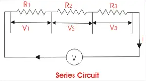
A series circuit is characterized by its linear sequence of components, through which the current flows in a single path. In such circuits, the total voltage is distributed across each component in proportion to its resistance. The overall resistance of a series circuit is equal to the sum of the individual resistances of the connected components. The unit of capacitance, the farad, measures a capacitor’s ability to store electric charge per unit voltage.

When they are connected in series, the total C of the circuit is affected. This is because the positive plate of the capacitors is connected in series to the total C. Each capacitor stores the same charge in this arrangement, and the total voltage is divided across the capacitors in proportion to their C. This characteristic of series-connected capacitors plays a significant role in designing electronic circuits that require specific voltage and charge distribution properties. To fully grasp how capacitors behave in series, it’s important to understand what is a capacitor and how it stores and releases electrical energy.


Capacitors in Series: Formula, Voltage, and Charge Characteristics

Feature Capacitors in Series
Total Capacitance Less than the smallest individual capacitor
Formula 1/Ctotal = 1/C₁ + 1/C₂ + 1/C₃ + ...
Voltage Distribution Voltage divides across capacitors based on capacitance values
Charge on Capacitors Same charge on all capacitors
Use Case Used when reduced overall capacitance is needed in a circuit
Energy Storage Lower total energy storage than a single capacitor with same voltage


Different types of capacitors, such as ceramic or electrolytic, behave differently in series configurations based on their construction and rated voltage.


Formula for Calculation

To accurately calculate the total C of capacitors connected in series, the following formula is employed:

C_total = 1 / (1/C1 + 1/C2 + 1/C3 + ... + 1/Cn)

This formula calculates the inverse of the total C. To find the actual total C, take the inverse of the sum of the inverse individual capacitances. This mathematical process enables the precise determination of the overall capacitance value in a series configuration, which is crucial when designing or analyzing electronic circuits.


Impact of the Smallest Capacitor on Total Capacitance

When several are connected in series, the total C becomes smaller than the smallest individual C. This phenomenon occurs because the capacitor with a smaller capacitance (C) limits the total capacitance (C), acting as a bottleneck for current flow and restricting the total charge stored in the circuit. Understanding this limiting effect is critical when selecting capacitors for a series configuration, as the smallest capacitor will significantly impact the overall performance of the electronic circuit. Engineers must also consider electrical resistance, which affects how current and voltage behave in conjunction with capacitors in mixed-component circuits.


Comparing Capacitors in Parallel and Series Configurations

In contrast to capacitors in series, when capacitors are connected in parallel, the total C is the sum of the individual capacitances. This difference occurs because each capacitor is directly connected to the power source in a parallel circuit, allowing it to store its charge independently. Consequently, capacitors in parallel configurations offer higher overall capacitance values, making them suitable for applications that require increased charge storage capabilities. Reviewing electrical resistance definition can help clarify how resistance and C work together in impedance-sensitive designs. You can explore how capacitance in parallel differs from series configurations when designing circuits requiring larger energy storage.


Equivalent Capacitance and Voltage Drop in Series Capacitors

The equivalent C of capacitors connected in series can be determined by dividing the total charge stored in the circuit by the total voltage across the circuit. This is because the total charge stored in the circuit equals the sum of the charges on each capacitor. In contrast, the total voltage is calculated to determine the total capacitance for the number of capacitors connected.

The voltage drop in capacitors connected in series is divided among the capacitors in proportion to their C. This means that the voltage across each capacitor is proportional to its C. Understanding the voltage drop distribution in series capacitors is essential when designing circuits that rely on specific voltage levels across components.


Replacing Capacitors in Series with a Single Equivalent Capacitor and Combination Circuits

In some cases, capacitors in series can be replaced with a single equivalent capacitor that has the same C value as the equivalent capacitance of the series capacitors. This replacement technique can simplify circuit design and analysis, consolidating multiple components into a single element with equivalent electrical properties.

In a combination circuit, capacitors are connected in both series and parallel configurations. These complex arrangements are commonly found in practical electronic applications, as they offer more flexibility and adaptability in achieving desired circuit properties. To calculate the total C of a combination circuit, first, compute the capacitance of each series combination, then add those capacitances to find the total C. This process may involve several steps, as the designer needs to consider the contributions of both series and parallel components to the overall C value.


Applications and Considerations of Capacitors in Series

Capacitors in series configurations are utilized in various electronic applications, such as power supply filtering, signal coupling, and decoupling, as well as in tuning and timing circuits. When designing these applications, engineers must consider the capacitors' voltage ratings, tolerances, temperature coefficients, and other parameters to ensure the circuit functions as desired.

One crucial consideration when working with capacitors in series is the voltage rating. The voltage rating of each capacitor must be sufficient to handle the voltage that will be applied across it. Since the total voltage is distributed among the capacitors in series, selecting capacitors with appropriate voltage ratings is essential to prevent component failure or degradation.

Another important consideration is the capacitors' tolerances, which indicate the possible variation in C values from their nominal specifications. Capacitors with tighter tolerances may be required for precise applications, as variations in C values can impact the overall performance of the electronic circuit. 


Related Articles


View more

Active Power

Active power is the actual energy consumed by electrical equipment to perform useful work, such as lighting or running motors. It is measured in kilowatts (kW) and is essential for efficient power system design, load management, and energy billing accuracy.


What is "active power"?

Active power is the real power consumed in an AC circuit to perform useful work.

✅ Measured in kilowatts (kW)

✅ Powers resistive loads like heaters, lights, and motors

✅ Crucial for calculating energy usage and efficiency


In AC circuits, active power (P) refers to the component of electrical power that results in energy transfer to a load. It is the energy that performs work—such as producing motion, light, or heat—and is distinct from reactive power, which oscillates between source and load without being consumed.

Active Power Formula

The general formula for active power is:

P = VIcosθ

Where:

  • P = Active Power (watts)

  • V = RMS Voltage

  • I = RMS Current

  • θ = Phase angle between voltage and current

In real-world power systems, only the portion of the current in phase with the voltage contributes to active power. The portion out of phase results in reactive power and does not produce usable energy.


Equation 1


The above active power equation is valid for both sinusoidal and nonsinusoidal conditions. For sinusoidal condition, '1rn, resolves to the familiar form,


Equation 2


Sinusoidal and Non-Sinusoidal Conditions

The calculation of active power can differ slightly depending on waveform distortion:

  • For sinusoidal conditions, Equation 1 simplifies to the standard P = VIcosθ form.

  • For non-sinusoidal waveforms, the total active power includes the sum of contributions from all harmonic components. However, since voltage distortion is typically below 5% in most power systems, the simplified equation is usually accurate enough for practical purposes.


Real-World Example

A standard incandescent light bulb converts electrical power into visible light and heat. This is a classic case of active power at work—where the current and voltage are in phase, and virtually all supplied power is consumed usefully.


Active vs Reactive vs Apparent Power

It’s important to distinguish active power from related concepts:

  • Reactive Power (Q): Energy exchanged but not consumed, measured in kVAR.

  • Apparent Power (S): The vector sum of active and reactive power, measured in kVA.

  • Power Factor: The ratio of active power to apparent power (PF = P/S).

While active power does the real work, apparent power impacts system loading and reactive power affects voltage stability. See our power factor training for more.


Measurement and Application

Active power is typically measured using true RMS meters that calculate the average of the instantaneous product of voltage and current. Advanced power analyzers now offer direct measurement of real power in both clean and distorted systems.

Engineers use active power data for:

  • Energy consumption analysis

  • Load management and optimization

  • System efficiency evaluation

  • Compliance with energy standards


Related Reading


Frequently Asked Questions


What is active power used for?

Active power is used to perform real work in electrical systems, such as lighting, heating, and running motors.


Is active power the same as real power?

Yes. Active power, real power, and true power are interchangeable terms that refer to the same concept.


How is active power calculated?

It is calculated using the formula P = VIcosθ, where V and I are RMS voltage and current, and θ is the phase angle between them.

In summary, understanding active power is essential for designing efficient electrical systems and ensuring energy accountability. By distinguishing it from reactive and apparent power, professionals can improve system performance and reduce energy losses.


Related Articles


View more

Green Electricity

Green electricity integrates renewable energy sources such as solar PV, wind turbines, and hydropower into smart grids, improving power quality, decarbonization, efficiency, and reliability for industrial loads and utility-scale networks.


What is green electricity?

Green electricity is renewable-source power via smart grids to cut emissions and enhance system efficiency.

✅ Integrates PV, wind, hydro with power electronics and converters

✅ Enhances grid stability via inverters, FACTS, and smart protection

✅ Reduces CO2, improves efficiency, supports microgrids and storage


Green electricity is a term describing what is thought to be environmentally friendly sources of electricity. Typically, this refers to renewable and non-polluting energy power sources. For a broader perspective on how different technologies contribute, see this overview of sources of electricity across modern grids.

Green electricity includes natural energetic processes which can be harnessed with little pollution. Anaerobic digestion, geothermal power, wind power, small-scale hydropower, solar power, biomass power, tidal power and wave power fall under such a category. Some versions may also include power derived from the incineration of waste. Comparisons with other clean options are summarized in this guide to alternative electricity solutions used worldwide.


Energies Wind Electricity 
The winds that blow across the UK can be harnessed by turbines to provide Green electricity. Wind turbines sited in suitable locations already provide a small, but growing percentage of the UK's electricity, and are used successfully all around the world. In fact wind power is the world's fastest growing energy source! Wind turbine technology has greatly improved over the last ten years, making wind turbines quieter and more efficient so that electricity generated from the wind is now often competitive with traditional coal-fired and nuclear power stations. Wind turbines are also beginning to be built at sea — in the future much of our electricity could come from these offshore windfarms. Understanding how turbines integrate into national systems is covered in this primer on electricity generation methods and planning.


Solar Electricity
Many people believe that we don't get much solar Green electricity here in the UK. In fact solar power is already being used to provide essential power for many types of equipment being used in both remote and urban areas across the country. A solar photovoltaic (PV) module works by converting sunlight directly into electricity (even on cloudy days) using semiconductor technology. The vast majority of solar modules available today use "waste" silicon from the computer chip industry as the semiconductor material. They can be integrated into buildings and even made into roof tiles virtually indistinguishable from normal tiles. 
Solar Electricity can also be used to heat water directly using specially designed collectors. Even in winter a useful amount of hot water can be produced from roof top collectors. A third way to use solar energy is simply to design buildings to make maximum use of the sun. Using this so-called 'passive solar' approach, much of the energy that we currently use for heating, lighting and air conditioning can be saved. Homeowners can explore practical steps to generate electricity with rooftop PV and storage.


Hydro Electricity
Water turbines have been used to provide Green electricity for over 100 years and presently provide over 1% of the UK's electricity. Although most of the possible sites for large hydropower stations in the UK have already been developed, there is a large potential for smaller schemes. These can either use a small dam or work as a 'run of the river' system which has a minimal impact on the local environment. Design considerations for small schemes are outlined in this resource on water electricity systems for communities.


Wave Electricity
Many different devices have been designed over the years to try and capture some of this huge energy resource — the latest one has recently started generating Green electricity on the isle of Islay, off the West Coast of Scotland. In this machine waves hitting the shore are channelled into a large tube to power a specially designed turbine. With the proper support, wave power could provide a significant proportion of the UK's electricity needs in the future.


Tidal Electricity
Tidal power has been used in Britain for over a thousand years — at the time of the Doomsday book over 5,000 tide powered mills were recorded. Unlike other Green electricity renewable energy sources, which depend on the weather, tidal power is as predictable as the tides themselves. One way to capture tidal energy is to build a barrage across an estuary, storing water behind it as the tide rises and then releasing the stored water through turbines at low tide. Several sites around the UK could be suitable for this type of tidal system, the largest being the Severn Estuary. Another way is to use 'marine current turbines', which work like underwater wind turbines, harnessing tidal currents instead of the winds.


Geothermal Electricity
Geothermal energy comes from hot rocks deep underground. In some parts of the world steam comes to the surface and can be used to run steam turbines to produce Green electricity directly. In other places water can be pumped down and heated by the rocks to make steam. Geothermal energy can also be used to provide hot water and heating for buildings. Case studies of enhanced systems are available in this overview of geothermal electricity projects worldwide.


Biomass Electricity
Either agricultural wastes or specially grown plants can be used as a fuel to run small Green electricity power stations. As plants grow they absorb carbon dioxide (the main gas responsible for climate change) which is then released when the plants are burnt. So using biomass does not add any extra carbon dioxide into the atmosphere. Specially grown 'energy crops' provide not only an environmentally sound source of electricity, but also an important new opportunity for farmers. Analyses of supply chains and grid impacts appear in this review of electricity production from biomass and other renewables.


Landfill gas Converted to Electricity
As rubbish decomposes in the landfill sites where our household waste is dumped, it gives off methane gas. This gas can be captured and burnt in a gas turbine to produce an attractive Green electricity tariff. Burning the gas does give off carbon dioxide but since methane, which is emitted from the landfill site, is in fact a much more powerful greenhouse gas it is better to burn it than to allow the methane to escape into the atmosphere. There are already many landfill gas systems operating in the UK.


Waste Incineration Electricity
The UK generates an enormous amount of waste, and space at landfill sites is quickly running out. The best solution would be to recycle as much of the waste as possible, but instead incinerators are being constructed to burn the waste. In some cases the energy is being used to generate green electricity. However many environmentalists are still concerned about the emission of harmful dioxins and also about the loss of a valuable resources that could have been recycled. You can read about Greenpeace's views on incineration.


Related Articles

View more

Sign Up for Electricity Forum’s Newsletter

Stay informed with our FREE Newsletter — get the latest news, breakthrough technologies, and expert insights, delivered straight to your inbox.

Electricity Today T&D Magazine Subscribe for FREE

Stay informed with the latest T&D policies and technologies.
  • Timely insights from industry experts
  • Practical solutions T&D engineers
  • Free access to every issue

Live Online & In-person Group Training

Advantages To Instructor-Led Training – Instructor-Led Course, Customized Training, Multiple Locations, Economical, CEU Credits, Course Discounts.

Request For Quotation

Whether you would prefer Live Online or In-Person instruction, our electrical training courses can be tailored to meet your company's specific requirements and delivered to your employees in one location or at various locations.