Inductive Load Explained

By R.W. Hurst, Editor


inductive load

An inductive load is common in electrical systems and can significantly impact power quality. Understanding inductive and resistive loads, as well as their impact on the quality of your electricity, is essential for designing and operating an effective electrical system.


What is an Inductive Load?

An inductive load is an electrical device or component that consumes active power while storing energy in a magnetic field due to inductance.

✅ Common in motors, transformers, and relays

✅ Impacts power factor and reactive power demand

✅ Requires compensation with capacitors for efficiency


Power Quality Analysis Training

Power Factor Training

Request a Free Power Quality Training Quotation

In power systems, an inductive load affects the flow of electrical current through conductors, creating conditions that may necessitate careful monitoring. A hot wire and a neutral wire must be properly balanced to avoid hazards, while ground fault circuit interrupters play a vital role in protecting against dangerous faults. Recognizing early signs of a short circuit, such as tripped breakers or overheating, is essential for maintaining system reliability and preventing equipment damage.


How does it affect Power Quality?

Inductive load affects power quality by introducing reactive power into an electrical system. Reactive power is the power that an IL consumes but does not convert into useful work. This can cause a decrease in the overall PF of the system. A low power factor (PF) can result in increased losses, decreased efficiency, and increased power source costs. Additionally, inductive loads can cause voltage drops and fluctuations, which can affect the operation of other electrical devices. Because inductive devices consume reactive power, engineers often use the apparent power formula to calculate their influence on system demand.


What are the types of inductive load?

There are several types of inductive loads, including electric motors, transformers, and heating elements. Electric motors are used in a wide range of applications, from household appliances to industrial machinery. Transformers are used to step up or step down voltage in electrical systems. Heating elements, such as those used in ovens and stovetops, rely on the inductive heating effect to generate heat. One way to minimize the effect of inductive loads on power factor is by installing an automatic power factor controller.


Common examples include:

  • Electric motors: ILs are commonly found in electric motors used in various appliances, such as washing machines, refrigerators, and air conditioners. Electric motors require electrical energy to create a magnetic field that rotates the motor's shaft, resulting in a lagging current.

  • Transformers are devices used to transfer electrical energy from one circuit to another through electromagnetic induction. They are commonly used in distribution systems to step up or step down the voltage to the required level.

  • Fluorescent lights use a ballast to regulate the flow of electricity to the lamp. The ballast contains an IL that helps regulate the electrical current and voltage to the light.

  • Welding equipment: Welding equipment, such as arc welders, use ILs to create a strong magnetic field that is used to generate the heat required for welding.

  • Induction cooktops: Induction cooktops use magnetic fields to create heat, and this requires the use of ILs to generate the magnetic field.

  • Speakers: Speakers use ILs in their voice coils to create a magnetic field that moves the speaker cone and produces sound.

It's essential to understand the different types of electrical load in order to manage consumption and ensure the efficient operation of electrical systems. Different types of loads require different management strategies, and PF correction may be necessary to optimize energy efficiency. Accurate evaluation of an inductive circuit often requires an apparent power calculator to measure kVA, kVAR, and kW contributions.


Frequently Asked Questions

How can you measure the Power Factor of an inductive load?

The PF of an IL can be measured using a PF meter or a digital multimeter. These devices measure the PF by comparing the real power (the power that is actually converted into useful work) to the apparent power (the total power consumed by the load). The PF is then calculated as the ratio of the real power to the apparent power. Inductive devices are often compared with a resistive load, which converts all energy into heat or light without reactive power.


What is the difference between a resistive and an inductive load?

A resistive load is a type of electrical load that converts electrical energy into heat or light, such as an incandescent light bulb or a resistor. A resistive load has a PF of 1, meaning that all of the electricity consumed by the load is converted into useful work. In contrast, an IL stores energy in a magnetic field and has a PF of less than 1. This means that some of the electricity consumed by the load is not converted into useful work.


What are some common examples?

Some common examples of ILs include electric motors, transformers, and fluorescent lights. These loads are found in a wide range of applications, from household appliances to industrial machinery.


How can you reduce the impact of inductive load on a system?

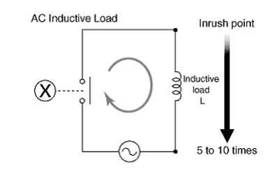
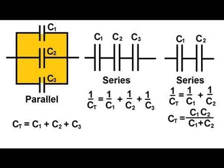
There are several ways to reduce the impact of ILs on an electrical system. One way is to improve the PF of the system by adding PF correction capacitors. These capacitors can help offset the reactive electricity consumed by ILs, thereby increasing the PF of the system. Another approach is to utilize soft starters or variable frequency drives with electric motors, which can reduce inrush current and minimize voltage fluctuations. Finally, using a high-efficiency supply or reducing the number of ILs in a system can also help reduce the impact of ILs on PQ. To balance inductive and capacitive elements, engineers apply power factor correction techniques that restore efficiency and reduce system losses.

By understanding the different types, measuring the PF, and reducing its impact on a system, electrical engineers can design and operate systems that are more efficient, reliable, and cost-effective.

It's worth noting that they are not the only types of electrical loads that can impact PQ. Capacitive loads, such as capacitors and fluorescent lights, can also introduce reactive power into a system. Additionally, purely resistive loads, such as resistors and incandescent light bulbs, do not introduce reactive power but can still affect PQ in other ways, including the generation of heat.

Understanding the different types of electrical loads and their impact on PQ is essential for designing and operating efficient and reliable electrical systems. While they can introduce reactive power and affect PF, there are ways to minimize their impact and improve PQ. By taking a holistic approach to electrical system design and operation, engineers can create systems that meet the needs of their users while minimizing costs and maximizing efficiency. Since inductive loads influence reactive currents, using the reactive power formula helps quantify their effect on power system design and operation.


Related Articles


Related News

Wattmeters – Power Measurement

Wattmeters measure electrical power in watts, monitoring energy use in industrial power systems. They provide accurate active power readings for efficiency and load management, utilizing voltage and current measurements to achieve precise results.


What are Wattmeters?

Wattmeters are instruments used to measure electrical power. They:

✅ Measure active electrical power in watts for various applications.

✅ Are used in industrial, commercial, and residential energy monitoring.

✅ Help optimize efficiency, manage loads, and ensure system safety.

A wattmeter measures instantaneous (or short-term) electrical power in watts, while a watthour meter accumulates that power over time and reports energy used (e.g. in kWh). Energy meters and smart meters extend this concept by recording consumption continuously for billing, load analysis, and energy audits.


Working Principle of Wattmeters

Electrical power is calculated using the formula:

P = E × I

Where:

  • P = Power in watts

  • E = Voltage in volts

  • I = Current in amperes

In DC circuits, watts are sometimes expressed as volt-amperes (VA). In AC circuits, wattmeters measure true (or active) power, taking into account the power factor to compensate for phase differences between voltage and current. Unlike reactive power (measured in kvar) or apparent power (measured in kVA), active power is the usable portion that does real work. This relationship is often represented in the power triangle, where vector analysis explains how apparent, reactive, and active power interact.


Construction and Internal Components

A typical wattmeter consists of two main coil assemblies:

  1. Current Coil (CC)

    • Heavy-gauge copper wire with low resistance.

    • Connected in series with the load to carry the circuit current.

  2. Voltage Coil (VC)

    • Fine-gauge wire with high resistance.

    • Connected in parallel with the load to measure voltage.

The electrodynamometer, commonly referred to as a dynamometer wattmeter, is a classic analog device that operates on the principle of a motor. The interaction between the magnetic fields of the current and voltage coils produces a torque proportional to the power, causing the pointer to move over a calibrated scale. Understanding wattmeter principles is a foundation of basic electricity training, helping learners connect theory to practical power measurement.


Figure 1 – Construction of a dynamometer wattmeter showing current and voltage coil arrangement.


Types of Wattmeters

  • Analog/Dynamometer – Durable, reliable, suited for laboratory and field measurements.

  • Digital – Higher accuracy, data logging, and integration with monitoring systems.

  • Clamp-on  – Measure power without breaking the circuit, ideal for quick diagnostics.

  • Specialized  – Designed for RF power, audio power, or other niche applications.

In three-phase systems, wattmeters are often applied in accordance with Blondel’s theorem, which specifies the number of measurement elements required in multi-phase circuits. They are frequently used in conjunction with 3 phase electricity concepts to ensure balanced load distribution and optimal system efficiency.


Fig. 2. Power can be measured with a voltmeter and an ammeter.


Measuring Power in DC and AC Circuits

In DC circuits, power measurement can be as simple as multiplying voltage and current readings from separate meters.

Example:

If a circuit operates at 117 V DC and draws 1 A, the power is:

P = 117 × 1 = 117 W

In AC systems, especially with reactive or distorted loads, a wattmeter is essential because voltage and current may not be in phase. The device automatically accounts for the phase angle, providing accurate true power readings. Advanced digital wattmeters also compensate for harmonic distortion and poor waveform quality, providing more reliable measurements than older analog designs.

By measuring energy transfer in circuits, they also relate to other power measurement instruments such as ammeters, voltmeters, and multimeters, which measure supporting parameters needed for complete electrical analysis. Accurate wattmeter readings are crucial for diagnosing performance issues in 3-phase power networks, where the relationships between voltage and current are critical. By measuring energy transfer in circuits, they help explain fundamental laws of electromagnetism, such as Ampère’s Law, which underpins the interaction between current and magnetic fields.


Fig. 2. Power can be measured with a voltmeter and an ammeter.


Practical Examples and Load Considerations

A household iron may consume 1000 W, drawing 8.55 A at 117 V.

A large heater may draw 2000 W, or 17.1 A, potentially overloading a 15 A breaker.

In industrial settings, watt meters help prevent equipment overloading, reduce downtime, and improve energy efficiency.


Modern Wattmeter Applications

Today’s wattmeters are often part of smart energy monitoring systems that:

  • Track energy consumption over time.

  • Integrate with SCADA and IoT platforms.

  • Enable predictive maintenance through power trend analysis.

  • Support compliance with energy efficiency regulations.


Accuracy, Standards, and Advanced Considerations

Measurement accuracy is a crucial factor in determining wattmeter performance. Devices are often classified by a class of accuracy, with error limits defined by international standards such as IEC, ANSI, or IEEE. Regular calibration and testing procedures ensure watt meters continue to deliver reliable results in both laboratory and field conditions.

Modern digital watt meters feature true RMS measurement, which accurately captures distorted waveforms caused by nonlinear loads. This is especially important in power systems where harmonic distortion is present. In commercial and industrial environments, accurate wattmeter data support energy audits, load analysis, and regulatory compliance, making them indispensable tools for engineers and facility managers. Wattmeter usage is closely linked to the fundamentals of electrical energy, enabling precise monitoring for efficiency and cost control.


Key Advantages of Wattmeters

  • Accurate real-time power measurement.

  • Enhanced energy management and cost savings.

  • Improved system reliability through overload prevention.

  • Compatibility with both AC and DC systems.

Wattmeters remain a vital tool for measuring and managing electrical power. Whether in a simple residential circuit, a commercial energy audit, or a high-tech industrial monitoring system, they ensure that electrical systems run efficiently, safely, and cost-effectively. As technology advances, digital and networked wattmeters continue to expand their role, integrating into smart grids and energy-optimized infrastructures. 


Related Articles


View more

Electricity Prices Explained

Electricity prices reflect tariffs, kWh rates, time-of-use schedules, peak demand charges, and grid congestion, driven by generation costs, transmission losses, and load profiles in power systems and industrial electrical engineering.


What Are Electricity Prices?

Electricity prices are costs per kWh shaped by tariffs, time-of-use, demand charges, and grid operating constraints.

✅ Defined per kWh with time-of-use and demand charges

✅ Influenced by generation mix, transmission losses, congestion

✅ Managed via load control, demand response, smart metering


Electricity prices, or rates, are usually determined by electric utilities and the governmental organizations that oversee them. The fees an electric utility company charges its customers for service aer based on electricity prices set by government, except in the case where they cost electricity prices on a deregulated basis. In that case, electricity prices are determined by marketplace factors such as supply and demand. Electric utility companies charge their customers different rates, depending on the type of customer, the kind of contract, and on the customer's needs. Electricity Prices bill energy on the kwh basis of the individual customer's rate, the level of consumption, and other charges, such as taxes and fuel adjustments. This is how electricity billed. For a deeper breakdown of typical rate components, resources like electricity cost guides explain line items and surcharges clearly.

That collection of rates is called a tariff. The power tariff is designed to provide the privately owned electric utility with enough income to allow investors to earn a cash return and cover operation and maintenance costs. Most of the larger utilities operate as regulated franchises, meaning that the prices they charge are subject to public review, often by a State public utility commission. In competitive markets, customers may choose an electricity supplier while the utility still handles delivery services and billing oversight.

Publicly owned electric utilities are nonprofit, local government agencies established to provide service to their communities and nearby consumers at cost, returning excess funds to the consumer in the form of community contributions, more economic and efficient facilities, and lower power rates. To meet these community objectives, public power agencies plan their electricity supply over multiyear horizons to manage risk and affordability.

Publicly owned electric utilities (which number approximately 2,000) include municipals, public power districts, State authorities, irrigation districts, and other State organizations. Some of these organizations also own or contract for electricity generation assets to enhance self-sufficiency and rate stability.

There are approximately 900 cooperative electric utilities in the United States currently doing business in 47 States. These utilities are owned by their members and are established to provide power to those members. Because member education supports better usage decisions, many cooperatives provide primers on what electricity is and how it is measured on bills.

Average retail Electricity prices of power are calculated by dividing utility revenue by retail sales. The resulting measurement is the cost, or average revenue per kilowatthour, of power sold. (A kilowatthour is equal to one watt of power supplied to an electric circuit steadily for 1,000 hours.) Electric utilities usually offer three primary classes of service: residential, commercial, and industrial. The average price per kilowatthour for residential consumers is generally higher than for any other sector due in part to higher costs associated with serving many consumers who use relatively small amounts of power. In Ontario, the industrial sector has the lowest energy prices and energy bills rates every month due to the economies of serving a few consumers who use relatively large amounts of electricity. Understanding the distinction between energy in kilowatthours and instantaneous electricity power demand helps customers interpret peak charges and capacity fees. Regional consumption patterns, including trends in electricity demand in Canada, can influence wholesale prices and cross-border power flows affecting local rates.


average retail


Related Articles

View more

Electricity Supplier - Make The Right Choice

Electricity supplier delivers power via transmission and distribution networks, managing tariffs, load forecasting, SCADA, and power quality, integrating renewables, smart meters, and demand response to ensure grid reliability, compliance, and efficient kWh billing.


What Is an Electricity Supplier?

An electricity supplier procures and delivers power, manages tariffs, and ensures grid reliability and power quality.

✅ Energy procurement and wholesale market participation

✅ Distribution coordination, SCADA monitoring, and outage management

✅ Tariff design, metering, billing, and power quality compliance


Who is my electricity supplier?

In Canada and the United States, it’s easy to learn which energy provider serves your property or residence. It depends on whether you are trying to find your electricity and natural gas supplier. Sometimes, homes and businesses have the power to choose their energy service utility company and the products and service they provide. Customers are free to choose. It's a competitive energy marketplace. For a plain-language primer on infrastructure, see the electricity supply overview to understand typical delivery steps.

If you use both services, your property might have the same local distribution company for both fuels, – commonly known as a "duel fuel supplier". But if your utility records are stored separately, you might need to more research to learn who supplies your natural gas services and your electricity services separately. If you are curious where the power originates, this guide to how electricity is generated explains common fuel sources and grid integration.


Here is a list of accredited Electricity Suppliers in Canada

https://www.ic.gc.ca/eic/site/mc-mc.nsf/eng/lm00525.html

Market dynamics can vary by province, and recent electricity demand trends in Canada help explain seasonal shifts in offers.


Here is a list of accredited Electricity Suppliers in the United States.

https://www.electricchoice.com/blog/25-top-providers-part-1/

When comparing providers, consult current electricity price benchmarks to contextualize quoted rates.


Who can supply electricity?

All electricity supplier companies must have a licence from the Office of Gas and Electricity Markets (Ofgem). One of the licence conditions is that a  company must produce codes of practice on:

Although the codes of practice are not legally enforceable, they will be useful when negotiating with a company and any breach should be reported to governmental regulatory authorities. Understanding the basics in this introduction to what electricity is can make those obligations clearer.


Choosing an electricity supplier

You can change your company if you wish. If you are considering changing your company you should be aware that the pricing structures, services offered and policies will differ between the different companies.You should carefully check the information and contracts of the competing electricity suppliers, and compare these to your current terms, to make sure that you choose the best deal for your needs. A lot depends on your gas bills or electricity bill, and your location by postal code. You can also estimate bill impacts by applying tips from this guide on how to save electricity while comparing plans.


Dual fuel offers

Dual fuel is the supply of gas and electricity by the same company. Some gas and electricity suppliers are licensed separately by Ofgem to supply customers with both fuels. Some companies will supply both fuels under one contract, while others will give one contract for gas and another for electricity. For households with high usage, reviewing your typical electricity power consumption patterns can reveal whether dual fuel makes financial sense.

Electricity Suppliers who make dual offers will often give a discount off the total bill as they can make administrative savings by issuing combined bills and collecting combined payments. However, this does not necessarily mean that the cost of gas and electricity

  • procedures for complaints
  • payment of bills, arrangements for dealing with arrears and prepayment meters
  • site access procedures
  • energy efficiency advice
  • services for older, disabled and chronically sick people. As part of this code of practice, the company must keep a register of these people and provide services to help those who are blind and partially sighted or deaf or hearing impaired. Especially during a power outage, it is important that these customers are restored asap.The customer may have to pay for some of these services.
    • how you will be charged for your electricity supply. Some companies may make a fixed standing charge and then a unit charge for the amount of electricity used; an company may not make a standing charge, but charge a higher unit price
    • whether different charges apply to different periods during the day
    • if cheaper prices are offered for particular payment methods, for example, if you pay by direct debit
    • what service standards each company is offering, for example, for repairs, extra help for older or disabled customers.All electricity suppliers must keep a list of their customers who ask to be identified as pensioners, chronically sick or disabled.The electricity supplier must tell all its customers that it keeps such a list and give information on how customers can be added to the list
    • the company's policies, for example, on debt and disconnection.


Related Articles

View more

Electrical Resistance Definition Explained

Electrical resistance definition explains how materials oppose current flow in circuits, measured in ohms, linked to voltage, resistivity, conductor geometry, temperature, and impedance, governed by Ohm's law and SI units in electronics.


What Is Electrical Resistance Definition?

It is the measure of how a material opposes electric current, equal to voltage divided by current and measured in ohms.

✅ Measured in ohms; per Ohm's law, resistance R equals voltage V over current I.

✅ Depends on material resistivity, length, cross-sectional area, and temperature.

✅ Key in circuit analysis, power dissipation, signal integrity, and safety.


Electrical Resistance Definition: ER occurs in an electrical circuit when current-carrying charged particles collide with fixed particles that make up the structure of the conductors. Resistance is measured in ohm. Resistance is the ohm w. Resistance occurs in every part of a circuit, including wires and especially power transmission lines. For a concise overview, see this introduction to electrical resistance to reinforce key definitions.

Dissipation of electric energy in the form of heat affects the amount of driving voltage required to produce a given current through the circuit. In fact, volts are mesured across a circuit divided by the current I (amperes) through that circuit defines quantitatively the amount of electrical resistance R. The ohm is the common unit of electrical resistance, equivalent to one volt per ampere and represented by the capital Greek letter omega, Ω. The electrical resistance of a wire is directly proportional to its length and inversely proportional to its cross-sectional area. Resistance also depends on the material of the conductor. For instance, the resistance of a conductor generally increases with increasing temperature the resistivity. This is why some conductors have almost zero resistance when cooled to extremely low temperatures, as is the case with superconductors, because of the relative resistivity of metals. There is a temperature coefficient of resistivity. If you need a refresher on potential difference and its role in circuits, review this explanation of voltage to connect the concepts.

Alternating-current resistors for current measurement require further design consideration. For example, if the resistor is to be used for current-transformer calibration, its ac resistance must be identical with its dc resistance within 1/100th% or better, and the applied voltage difference between its voltage terminals must be in phase with the current through it within a few tenths of a minute. Thin strips or tubes of resistance material are used to limit eddy currents and minimize "skin" effect, the current circuit must be arranged to have small self-inductance, and the leads from the voltage taps to the potential terminals should be arranged so that, as nearly as possible, the mutual inductance between the voltage and current circuits opposes and cancels the effect of the self-inductance of the current circuit. In (a) a metal strip has been folded into a very narrow U; in (b) the current circuit consists of coaxial tubes soldered together at one end to terminal blocks at the other end; in (c) a straight tube is used as the current circuit, and the potential leads are snugly fitting coaxial tubes soldered to the resistor tube at the desired separation and terminating at the center. These design choices are also easier to contextualize by comparing common types of resistors used for precise AC measurements.

Electrical Resistance coils consist of insulated resistance copper wire wound on a bobbin or winding form, hard-soldered at the ends to copper terminal wires. Metal tubes are widely used as winding form for dc resistors because they dissipate heat more readily than insulating bobbins, but if the resistor is to be used in ac measurements, a ceramic winding form is greatly to be preferred because it contributes less to the phase-defect angle of the resistor. The resistance wire ordinarily is folded into a narrow loop and wound bifilar onto the form to minimize inductance. This construction results in considerable associated capacitance of high-resistance coils, for which the wire is quite long, and an alternative construction is to wind the coil inductively on a thin mica or plastic card. The capacitive effect is greatly reduced, and the inductance is still quite small if the card is thin. When specifying coil assemblies, it helps to recall the standardized unit of electrical resistance so ratings and tolerances are interpreted consistently.

Resistors in which the wire forms the warp of a woven ribbon have lower time constants than either the simple bifilar- or card-wound types. Manganin is the resistance material most generally employed, but Evanohm and similar alloys are beginning to be extensively used for very high resistance coils. Enamel or silk is used to insulate the wire, and the finished coil is ordinarily coated with shellac or varnish to protect the wire from the atmosphere. Such coatings do not completely exclude moisture, and dimensional changes of insulation with humidity will result in small resistance changes, particularly in high resistances where fine wire is used. Material behavior, moisture effects, and long term stability are discussed further in this broader overview of electrical resistance for additional context.

Electrical Resistance boxes usually have two to four decades of resistance so that with reasonable precision they cover a considerable range of resistance, adjustable in small steps. For convenience of connection, terminals of the individual resistors are brought to copper blocks or studs, which are connected into the circuit by means of plugs or of dial switches using rotary laminated brushes; clean, well-fitted plugs probably have lower resistance than dial switches but are much less convenient to use. The residual inductance of decade groups of coils due to switch wiring, and the capacitance of connected but inactive coils, will probably exceed the residuals of the coils themselves, and it is to be expected that the time constant of an assembly of coils in a decade box will be considerably greater than that of the individual coils. Understanding how series and parallel combinations set the equivalent resistance will inform how decade boxes are deployed in complex networks.

Measurement of resistance is accomplished by a variety of methods, depending on the magnitude of the resistor and the accuracy required. Over the range from a few ohms to a megohm or more, an ohmmeter may be used for an accuracy of a few percent. A simple ohmmeter may consist of a milliammeter, dry cell, and resistor in a series circuit, the instrument scale being marked in resistance units, if you obey ohm law. For a better value, the voltage drop is measured across the resistor for a measured or known current through it. Here, accuracy is limited by the instrument scales unless a potentiometer is used for the current and voltage measurements. The approach is also taken in the wide variety of digital multimeters now in common use. Their manufacturers' specifications indicate a range of accuracies from a few percent to 10 ppm (0.001%) or better from the simplest to the most precise meters. Bridge methods can have the highest accuracy, both because they are null methods in which two or more ratios can be brought to equality and because the measurements can be made by comparison with accurately known standards. For two-terminal resistors, a Wheatstone bridge can be used; for four-terminal measurements, a Kelvin bridge or a current comparator bridge can be used. Bridges for either two- or four-terminal measurements also may be based on resistive dividers. Because of their extremely high input impedance, digital voltmeters that be used with standard resistors in unbalanced bridge circuits of high accuracy. For quick reference during test planning, the fundamental resistance formula clarifies how R, V, and I are related under Ohm law.

Digital multi meters are frequently used to make low-power measurements of resistors in the range between a few ohms and a hundred megohms or so. Resolution of such instruments varies from 1% of full scale to a part per million of full scale. These meters generally use a constant-current source with a known current controlled by comparing the voltage drop on an internal "standard" resistor to the EMF produced by a Zener diode. The current is set at such a level as to make the meter direct-reading in terms of the displayed voltage; that is, the number displayed by the meter reflects the voltage drop across the resistor, but the decimal point is moved and the scale descriptor is displayed as appropriate. Multimeters typically use three or more fixed currents and several voltage ranges to produce seven or more decade ranges with the full-scale reading from 1.4 to 3.9 times the range. For example, on the 1000-0 range, full scale may be 3,999.999 Q. Power dissipated in the measured resistor generally does not exceed 30 mW and reaches that level only in the lowest ranges where resistors are usually designed to handle many times that power. The most accurate multimeters have a resolution of 1 to 10 ppm of range on all ranges above the 10-0 range. Their sensitivity, linearity, and short-term stability make it possible to compare nominally equal resistors by substitution with an uncertainty 2 to 3 times the least count of the meter. This permits their use in making very accurate measurements, up to 10 ppm, or resistors whose values are close to those of standards at hand. Many less expensive multimeters have only two leads or terminals to use to make measurements. In those cases, the leads from the meter to the resistor to be measured become part of the measured


Related Articles

View more

Electricity Production

Electricity production converts primary energy into power via thermal, hydro, wind, and solar systems, optimizing efficiency, capacity factor, grid stability, transmission reliability, and emissions through turbines, generators, inverters, and advanced SCADA control.


What Is Electricity Production?

Electricity production converts energy to electric power, prioritizing efficiency, safety, and grid reliability.

✅ Conversion via turbines, generators, inverters, and transformers

✅ Control with SCADA, protective relays, and load-frequency regulation

✅ Optimization of efficiency, capacity factor, and emissions


Electricity Production continues to grow around the world, from a variety of energy power sources. In terms of world electricity generation, the US Department of Energy predicts advances strongly from 2004 to 2030. Global production increases by 2.4 percent per year over the projection period, from 16,424 billion kilowatthours in 2004 to 30,364 billion kilowatthours in 2030. Much of the growth in electric power demand is projected for nations outside the OECD. Although the non-OECD nations consumed 26 percent less electricity than the OECD nations in 2004, total generation in the non-OECD region in 2030 is projected to exceed generation in the OECD by 30 per cent. For context, the International Energy Outlook provides a concise overview of electricity generation trends worldwide today.

Total electricity demand in the non-OECD nations is expected to grow from 2004 to 2030 at an annual rate that is nearly triple the rate of growth for electricity demand in the OECD. The difference reflects the relative maturity of electricity infrastructure in the more developed OECD region, as well as the expectation that populations in the OECD countries generally will grow slowly or decline over the next 25 years. In addition, fast-paced growth in the developing non-OECD economies translates to rising standards of living and robust growth in consumer demand for lighting and appliances. Total electricity generation in the non-OECD region increases by an average of 3.5 percent per year in the IEO2007 reference case, as compared with a projected annual growth rate for OECD electricity generation that averages 1.3 per cent per year from 2004 to 2030. Among the energy end-use sectors, the most rapid growth in total world demand for electricity is projected for the buildings (residential and commercial) sectors.

Understanding the diversity of sources of electricity helps explain regional growth patterns in demand.

In Power plants, electricity Production involves the generation or creation of electric power, using rotating turbines attached to an energy generator. This mechanical manufacturing of electricity produces most commercially available electricity. Turbines are driven by a fluid which acts as an intermediate energy carrier. The fluids typically used are:

For readers new to plant design, this primer on how electricity is generated clarifies the roles of turbines, generators, and working fluids.

  • steam - Water is boiled by nuclear fission or the burning of fossil fuels (coal, natural gas, or petroleum). Some newer plants use the sun as the heat source: solar parabolic troughs and solar power towers concentrate sunlight to heat a heat transfer fluid, which is then used to produce steam. Another renewable source of heat used to drive a turbine is Geothermal power. Either steam under pressure emerges from the ground and drives a turbine or hot water evaporates a low boiling liquid to create vapour to drive a turbine.
  • water - Turbine blades are acted upon by flowing water, produced by hydroelectric dams or tidal forces,
  • wind - Most wind turbines generate electricity from naturally occurring wind. Solar updraft towers use wind that is artificially produced inside the chimney by heating it with sunlight.
  • hot gases - Turbines are driven directly by gases produced by the combustion of natural gas or oil. Combined cycle gas turbine plants are driven by both steam and gas. They generate power by burning natural gas in a gas turbine and use residual heat to generate additional electricity generation from steam. These plants offer efficiencies of up to 60%.

Hydropower and tidal technologies illustrate how water-based electricity remains a cornerstone in many regions.

Various other technologies have been studied and developed for power generation. Solid-state generation (without moving parts) is of particular interest in portable applications. This area is largely dominated by thermoelectric (TE) devices, though thermionic (TI) and thermophotovoltaic (TPV) systems have been developed as well. Typically, TE devices are used at lower temperatures than TI and TPV systems. Piezoelectric devices are used for power generation from mechanical strain, particularly in power harvesting. Betavoltaics are another type of solid-state power generator which produces electricity from radioactive decay. Beyond conventional turbines, a range of alternative electricity options are being explored for niche and distributed applications.

Fluid-based magnetohydrodynamic (MHD) electricity generation has been studied as a method for extracting electrical power from nuclear reactors and also from more conventional fuel combustion systems. These advanced concepts broaden our understanding of how we generate electricity under extreme conditions.

Electrochemical is also important in portable and mobile applications. Currently, most electrochemical power comes from closed electrochemical cells ("batteries"), which are arguably utilized more as storage systems than generation systems, but open electrochemical systems, known as fuel cells, have been undergoing a great deal of research and development in the last few years. Fuel cells can be used to extract power either from natural fuels or from synthesized fuels (mainly electrolytic hydrogen) and so can be viewed as either generation systems or storage systems depending on their use. In many systems the electricity generator ultimately interfaces with inverters and controls for grid integration.


Related Articles

View more

What is the Electricity Demand In Canada?

Electricity demand Canada drives load forecasting, grid reliability, peak demand management, renewable integration, and capacity planning across provinces, informing energy consumption trends, transmission constraints, demand response programs, and ISO market operations.


What Is Electricity Demand Canada?

It is the national electrical load across sectors guiding forecasting, grid planning, and reliability.

✅ Provincial load profiles and peak diversity analysis

✅ Demand response and time-of-use optimizing peak loads

✅ Transmission constraints and capacity expansion planning


Electricity Demand in Canada will continue to put, in the longer term, upward pressure on prices for consumers in both regulated and restructured or deregulated markets. For context, market fundamentals and policy design both shape electricity prices across provinces today, influencing bills over time.

These dynamics play out within an integrated electric power system that balances reliability, affordability, and decarbonization goals.

These pricing impacts will be felt due to the cost of developing new generation and transmission facilities in order to replace ageing infrastructure and due to the increased use of renewable sources of generation (e.g., wind, solar, biomass). Continued strength of oil and gas prices are expected to keep electricity prices higher in regions that rely on natural gas and oil products as input fuels for power generation. Understanding the mix of hydro, wind, solar, nuclear, and gas requires a grasp of how electricity is generated across Canada’s grid components.

With the exception of Ontario (due to its large summer seasonal air conditioning requirement for electricity demand, Canada is a winter-peaking system and so the highest demand loads usually occur in the winter. However, for provinces that have competitive wholesale markets (e.g. Alberta and Ontario), near-term price pressures could result from the increase in summer cooling demand. Prices could also experience additional upward pressure from fuels used to generate electricity; namely, oil and natural gas. These pressures could be further supported by unusual weather events, unplanned generation outages and transmission system failures. If wholesale price pressures are to be passed on to consumers, the cost impact would likely not be felt immediately. Instead, such costs would need to go through a review process in all provinces and be approved by the energy regulatory board of that respective province. Tight reserve margins can constrain electricity supply during extreme temperature events, amplifying short-term price volatility.

Consumer prices or "rates" vary for several reasons:

In many jurisdictions, the total electricity cost combines generation, transmission, distribution, and rider charges that appear separately on bills.


  • variation in generation costs; prices in hydro-based provinces tend to be lower (e.g., British Columbia, Manitoba and Quebec);
  • customer class (e.g., residential, commercial, industrial);
  • residential rates tend to be higher than commercial and industrial rates;
  • amount of energy consumed in a given period (e.g., rates may vary based on customer consumption);
  • time-of-use pricing (e.g., some consumers have access to time of use meters that show lower charges for electricity during off peak periods);
  • and capability to switch to lower cost fuels (e.g. industrial customers)

Consumers in deregulated provinces can compare plans from an electricity supplier to align contract terms and risk with their usage profile.


Electricity demand Canada in peak periods typically occurs during the winter months, although, at times, Ontario and Quebec experience peak electricity demand in the summer months due to increased use of air conditioning units. Spring and fall tend to be shoulder seasons with lower demand. Seasonal patterns also influence maintenance schedules for electricity generation across provinces, which can tighten supply during cold snaps or heat waves.


Related Articles

View more

Sign Up for Electricity Forum’s Newsletter

Stay informed with our FREE Newsletter — get the latest news, breakthrough technologies, and expert insights, delivered straight to your inbox.

Electricity Today T&D Magazine Subscribe for FREE

Stay informed with the latest T&D policies and technologies.
  • Timely insights from industry experts
  • Practical solutions T&D engineers
  • Free access to every issue

Download the 2025 Electrical Training Catalog

Explore 50+ live, expert-led electrical training courses –

  • Interactive
  • Flexible
  • CEU-cerified