Electricity Prices Explained


Electricity Prices

Electricity prices reflect tariffs, kWh rates, time-of-use schedules, peak demand charges, and grid congestion, driven by generation costs, transmission losses, and load profiles in power systems and industrial electrical engineering.


What Are Electricity Prices?

Electricity prices are costs per kWh shaped by tariffs, time-of-use, demand charges, and grid operating constraints.

✅ Defined per kWh with time-of-use and demand charges

✅ Influenced by generation mix, transmission losses, congestion

✅ Managed via load control, demand response, smart metering


Electricity prices, or rates, are usually determined by electric utilities and the governmental organizations that oversee them. The fees an electric utility company charges its customers for service aer based on electricity prices set by government, except in the case where they cost electricity prices on a deregulated basis. In that case, electricity prices are determined by marketplace factors such as supply and demand. Electric utility companies charge their customers different rates, depending on the type of customer, the kind of contract, and on the customer's needs. Electricity Prices bill energy on the kwh basis of the individual customer's rate, the level of consumption, and other charges, such as taxes and fuel adjustments. This is how electricity billed. For a deeper breakdown of typical rate components, resources like electricity cost guides explain line items and surcharges clearly.

That collection of rates is called a tariff. The power tariff is designed to provide the privately owned electric utility with enough income to allow investors to earn a cash return and cover operation and maintenance costs. Most of the larger utilities operate as regulated franchises, meaning that the prices they charge are subject to public review, often by a State public utility commission. In competitive markets, customers may choose an electricity supplier while the utility still handles delivery services and billing oversight.

Publicly owned electric utilities are nonprofit, local government agencies established to provide service to their communities and nearby consumers at cost, returning excess funds to the consumer in the form of community contributions, more economic and efficient facilities, and lower power rates. To meet these community objectives, public power agencies plan their electricity supply over multiyear horizons to manage risk and affordability.

Publicly owned electric utilities (which number approximately 2,000) include municipals, public power districts, State authorities, irrigation districts, and other State organizations. Some of these organizations also own or contract for electricity generation assets to enhance self-sufficiency and rate stability.

There are approximately 900 cooperative electric utilities in the United States currently doing business in 47 States. These utilities are owned by their members and are established to provide power to those members. Because member education supports better usage decisions, many cooperatives provide primers on what electricity is and how it is measured on bills.

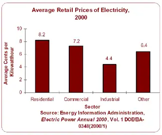
Average retail Electricity prices of power are calculated by dividing utility revenue by retail sales. The resulting measurement is the cost, or average revenue per kilowatthour, of power sold. (A kilowatthour is equal to one watt of power supplied to an electric circuit steadily for 1,000 hours.) Electric utilities usually offer three primary classes of service: residential, commercial, and industrial. The average price per kilowatthour for residential consumers is generally higher than for any other sector due in part to higher costs associated with serving many consumers who use relatively small amounts of power. In Ontario, the industrial sector has the lowest energy prices and energy bills rates every month due to the economies of serving a few consumers who use relatively large amounts of electricity. Understanding the distinction between energy in kilowatthours and instantaneous electricity power demand helps customers interpret peak charges and capacity fees. Regional consumption patterns, including trends in electricity demand in Canada, can influence wholesale prices and cross-border power flows affecting local rates.

Related News

Prospective Fault Current Meaning Explained

Prospective fault current (PFC) is the highest electric current that can flow in a system during a short circuit. It helps determine equipment ratings, breaker capacity, and safety measures in electrical installations to prevent overheating, fire, or component failure.


What is the Meaning of Prospective Fault Current?

Prospective fault current refers to the maximum current expected during a short circuit at any point in an electrical system.

✅ Helps size circuit breakers and fuses for safe disconnection

✅ Ensures compliance with installation and safety codes

✅ Prevents equipment damage from excessive short-circuit current

Prospective fault current (PFC) is a key factor in the safety and design of electrical systems. It represents the maximum current that could flow in the event of a fault, such as a short circuit. Understanding PFC is essential for selecting protective devices that can handle fault conditions safely. This article explores what PFC is, how it is measured, and its importance for electrical installations, while addressing key questions. Understanding electrical short circuits is key to calculating prospective fault current and ensuring system safety.

When measuring prospective short circuit current in an electrical system, it’s essential to perform tests between L1 N CPC and L2 N CPC to assess the fault current across different phases and protective conductors. These measurements help identify the maximum prospective fault current present in the system, especially at points involving live conductors. Whether taking note of a single-phase supply or between line conductors on a three-phase supply, proper testing protocols must be followed. Technicians should always use insulated test leads rated for the expected voltage and current levels, and please refer to the test meter manufacturer’s instruction for safe and accurate operation. Reliable results ensure that the protective devices can safely interrupt fault conditions, preventing system damage and ensuring compliance with fault current protection standards.


Frequently Asked Questions

Why is it Important?

Prospective fault current refers to the maximum current that could pass through a system during a fault. The PFC helps determine the breaking capacity of fuses and circuit breakers, ensuring these protective devices can handle high currents safely. This is vital for protecting the electrical installation and those working near it.

Understanding PFC is critical for ensuring increased safety for employees and third parties. Protective devices must be selected to handle PFC; otherwise, they may fail to operate correctly, leading to severe consequences, such as fires or injuries. To fully grasp how PFC affects energy flow, it’s useful to review the concept of electrical resistance in a circuit.


How is Prospective Fault Current Measured or Calculated?

PFC can be measured or calculated using tools such as a multifunction tester, often during fault current testing. The instrument uses a single-phase supply or between line conductors on a three-phase supply to measure the maximum potential current at various points in the installation. Testing often involves checking currents between L1 N CPC, L2 N CPC, and L3 N CPC, which measure current between the lines to neutral in a three-phase system.

When performing these tests, technicians should follow regulation 612.11 of a single-phase supply or between line conductors on a three-phase supply, ensuring that simple and circuit protective conductors are all connected correctly. Accurate testing must also account for maximum current flow. Live testing requires extreme caution, and it is important to refer to the test meter manufacturer’s instructions to ensure proper usage and safety. In three-phase systems, 3-phase electricity significantly impacts how fault current behaves during a short circuit.


What is the difference between PFC and Short-Circuit Current?

Though often confused, prospective fault current and short-circuit current are distinct. Prospective fault current is the theoretical maximum current that could flow in a fault, used to predict the worst-case scenario for selecting protective devices. Short-circuit current refers to the actual current that flows during a fault, which depends on real-time conditions such as circuit impedance. Prospective fault current is one of the many concepts that form the foundation of electricity fundamentals.


How Does Prospective Fault Current Impact the Selection of Protective Devices?

The calculation of PFC plays a critical role in selecting the correct protective devices. Circuit breakers and fuses must have a breaking capacity that matches or exceeds the prospective fault current in the system. If the PFC exceeds the breaking capacity, the protective device may fail, leading to dangerous electrical hazards.

For instance, fault current testing using a multifunction tester between phases and neutral (L1, L2, L3) ensures that protective devices are rated to handle the highest potential fault current in the system. Proper circuit protection ensures that the system can interrupt faults safely, minimizing the risks to workers and equipment.


What Standards and Regulations Govern Prospective Fault Current Calculations?

Various standards, such as IEC 60909, govern how PFC is calculated and how protective devices are selected. These regulations ensure that electrical systems are designed to handle maximum fault conditions safely. Regulation 612.11 further specifies how live testing should be conducted using proper equipment and safety protocols.

It is essential to test PFC at relevant points in the system and follow testing standards to ensure compliance and safety. Devices selected based on PFC calculations help ensure that electrical systems can withstand faults and maintain reliable operation.

Prospective fault current is a crucial element in the safety and reliability of electrical installations. By calculating PFC, engineers can select protective devices that ensure safe operation in the event of a fault. Testing for fault currents at different points in the system and adhering to regulations are essential steps in preventing hazardous conditions.

By choosing protective devices with the appropriate breaking capacity and following safe testing practices, electrical installations can handle fault conditions and protect both workers and equipment from harm. Selecting protective devices that match the PFC is essential for reliable electric power systems design.


Related Articles


View more

Electromagnetic Induction

Electromagnetic induction is the process of generating electric current by changing a magnetic field, forming the basis for transformers, generators, and electric motors in power generation and energy conversion systems.


What is Electromagnetic Induction?

Electromagnetic induction is a fascinating and vital concept shaping how we generate, transfer, and utilize electricity.

✅ Process where a changing magnetic field induces an electric current in a conductor

✅ Fundamental principle behind transformers, generators, and electric motors

✅ Essential for modern power generation, transmission, and energy conversion


Its underlying principles, Faraday's Law and Lenz's Law, explain the phenomena occurring when magnetic fields interact with conductors. At the same time, its various applications, such as electric generators, transformers, induction heating, and wireless charging, have revolutionized our daily lives. As we continue to explore and understand this intricacy, we can look forward to even more innovations and advancements in electricity and magnetism. Understanding Faraday's Law is essential to grasp how changing magnetic fields generate electricity through electromagnetic induction.


Fundamental Laws of Electromagnetic Induction

Faraday's Law of electromagnetic induction, invented by Michael Faraday, is a key principle that states that the induced EMF in a coil is proportional to the rate of change of the magnetic flux (dφ/dt) passing through the coil. The more rapidly the magnetic field changes, the higher the amount of voltage induced will be. This relationship between electricity and magnetism laid the foundation for the development of various electrical devices and systems. The relationship between electricity and magnetism forms the foundation of generators, transformers, and other key electrical systems.

Lenz's Law, another crucial principle, explains the direction of the induced current. It states that the induced current will always flow in a direction that opposes the change in magnetic flux, acting as a stabilizing electromotive force. By combining Faraday's and Lenz's Law, we can better understand how it operates in real-world applications. For a deeper understanding of how voltage is produced in coils, explore the principles of Lenz's Law.


Core Applications: Generators and Transformers

One notable application is the electrical generator, which converts mechanical energy into electrical energy. In a typical generator, a coil of wire rotates within a magnetic field, creating a changing magnetic flux. This change induces a voltage and current in the coil, generating electricity. Generators are commonly used in power plants, automobiles, and other devices requiring a continuous electrical supply. A three-phase transformer uses electromagnetic induction to efficiently transfer power between circuits at different voltages.

Another critical application is the transformer, which transfers electrical energy between circuits with different voltages. Transformers consist of two induction coils wrapped around a shared magnetic core. When an alternating current flows through the primary coil, it creates a magnetic field that induces a voltage in the secondary coil. By adjusting the number of turns in the coils, transformers can step up or down the voltage as needed for specific electrical systems.


Special Phenomena: Eddy Currents, Mutual Inductance, and Self-Inductance

Eddy currents are an intriguing aspect of electromagnetic induction. These currents form when a magnetic field changes, causing swirling, closed loops of electric current within a conductor. Eddy currents generate heat and can lead to energy losses in electrical systems, but they also have practical applications, such as in metal detectors and induction heating. Devices that use electromagnetic induction, such as electric motors, rely on core principles of inductance to regulate energy transfer.

Two critical aspects of electromagnetic induction are mutual inductance and self-inductance. Mutual inductance occurs when the current in one coil induces a voltage in a nearby coil due to their shared magnetic field. Self-inductance refers to a coil's ability to induce a voltage within itself when the current flowing through it changes. Understanding these concepts is crucial for designing and analyzing complex electrical circuits and systems.


Demonstrating the Principle: Coil and Magnet Interaction

In many cases, it involves the interaction of a coil and a magnet, either a permanent magnet or an electromagnet. A bar magnet, for example, may be moved near a coil, or the coil may be moved about the magnet. This motion changes the magnetic field and induces a voltage in the coil, demonstrating the dynamic relationship between electricity and magnetism. Learning the basics of electrical resistance helps explain how eddy currents generate heat in conductive materials.


Modern Impact and Emerging Technologies

It has an immense impact on modern life, from generating electricity in power plants to operating devices like transformers, electric motors, and wireless chargers. The principles of Faraday's Law and Lenz's Law help explain the complex phenomena that occur when magnetic fields interact with conductors. By harnessing these principles, scientists and engineers have created various practical applications that have revolutionized our daily lives.

Electromagnetic induction demonstrates the fundamental relationship between electricity and magnetism and is integral to many aspects of our modern world. Faraday's Law and Lenz's Law underpin this phenomenon, governing the induced voltage and current when magnetic fields change. The applications of electromagnetic induction range from electric generators and transformers to the study of eddy currents, mutual in influence and self-inductance. By understanding these principles, we can continue to innovate and develop new technologies to improve our daily lives and advance our understanding of the world.


Induction Heating

Electromagnetic induction heating is another practical application that relies on electromagnetic induction. This technology utilizes eddy currents to heat conductive materials, such as metals. By placing a conductive material within a rapidly changing magnetic field, eddy currents are generated within the material, producing heat due to their resistance. This heating method has been employed in various industrial processes, including metal hardening, welding, and cooking.

Wireless charging is an emerging technology that utilizes electromagnetic induction to transfer energy between two coils. When an electric current flows through the primary coil, it generates a magnetic field, which induces a voltage in the secondary coil, providing power to the device. This technology has seen increasing adoption in recent years, particularly for charging electric vehicles and smartphones, offering convenience and reduced dependence on cords and cables.


Related Articles


View more

Impedance Definition

Impedance Definition Explained

Understanding the concept of impedance (Z) is crucial for anyone working with or studying electrical circuits, particularly those involving alternating current (AC). To grasp the intricacies of impedance, it is essential to explore its definition and the various factors that come into play.

The term "impedance" is defined as the opposition that an electrical circuit presents to the flow of an alternating current (AC) or voltage. It is a complex quantity that includes both resistance and reactance components, making it vital in AC circuit analysis. Electrical impedance is essential in determining how electrical energy flows through a circuit, and it is influenced by various factors such as resistance, reactance, and frequency.

Resistance and reactance are two key elements that make up impedance. While resistance is the opposition to the flow of direct current (DC), reactance opposes the flow of AC. Reactance itself is composed of two parts: capacitive and inductive impedance. Capacitive impedance is due to the presence of capacitors in the circuit, while inductive impedance results from the presence of inductors.

Impedance is crucial in AC circuit analysis because it enables engineers and technicians to calculate how AC voltage and current behave within a circuit. This knowledge is necessary when designing and troubleshooting electrical systems. Furthermore, understanding impedance helps identify the optimal conditions for efficient energy transfer, as demonstrated by impedance matching.


Impedance matching refers to adjusting the Z of a source and load to match, maximizing the power transfer between the two. This is essential in various applications such as radio frequency (RF) communications, audio systems, and power transmission.

Calculating the total impedance (Z_total) in a circuit involves considering both the resistive and reactive components. For a series circuit, the total impedance is calculated using Ohm's law as follows:


Z_total = √ (R_total^2 + (X_L - X_C)^2)


Here, Z_total represents total impedance, R_total is the total resistance, X_L is the inductive reactance, and X_C is the capacitive reactance. In parallel circuits, the total impedance is computed by determining the reciprocal of the sum of the reciprocals of individual impedances.

Capacitive and inductive impedance play significant roles in AC circuits. As the frequency of the AC signal changes, the impedance of capacitors and inductors in the circuit also changes. As a result, capacitive impedance decreases with increasing frequency while inductive impedance increases. This characteristic can be utilized to design filters that selectively allow specific frequency ranges to pass through, shaping the output signal as desired.

Impedance spectroscopy is a technique that examines the Z of a material or device over a range of frequencies. This process provides valuable information on the electrical properties and behaviour of the material, enabling researchers and engineers to gain insight into various phenomena such as conductivity, dielectric properties, and electrochemical reactions. This knowledge can be applied to optimize the design and performance of various materials and devices.

Impedance definition and its various aspects, including electrical impedance, complex impedance, impedance matching, and impedance spectroscopy, are essential to understanding AC circuit analysis and the behaviour of electrical circuits in different applications. By examining the interplay of resistance and reactance and the influence of electric and magnetic fields, engineers can design and optimize circuits to ensure maximum efficiency and functionality.

View more

Electricity Grid - T&D

Electricity grid infrastructure delivers power through transmission lines, substations, and smart grid controls, balancing voltage and frequency, integrating renewable energy, enabling demand response, improving reliability, and supporting utilities with real-time monitoring and load management.


What Is the Electricity Grid?

A network of transmission, distribution, and control systems that delivers reliable electrical power to consumers.

✅ Transmits high-voltage power from plants to local networks

✅ Steps down voltage at substations for safe distribution

✅ Integrates renewables with smart grid and demand response


The electricity grid is a complex and essential component of modern society. It provides the power necessary to operate homes, businesses, and industries, and it is constantly evolving to meet the demands of a changing world. From power generation to distribution, transmission lines to load balancing and renewable energy integration, every component is critical in ensuring we can access reliable and affordable energy whenever needed. For a broader primer, resources such as electric power systems outline how these elements interconnect in practice.

At its core, the grid is a system that connects power generation facilities to consumers through transmission lines and distribution systems. It is designed to move electricity from where it is generated to where it is needed, whether in a residential home or a large industrial facility. The term "grid" refers to the interconnectedness of these systems, which allows power to flow from one location to another as needed. The federal energy regulatory commission ferc regulates the grid.

In North America, the transmission and distribution (T&D) grid is managed by federal, state, provincial, and territorial agencies. The grid is divided into various regions, each with its grid operator responsible for ensuring reliable and efficient operation within their respective jurisdiction. For instance, Canada's power delivery network is divided into four main regions: Western Canada, Ontario, Quebec, and the Atlantic region. Similarly, the United States' electricity grid is divided into three major interconnected systems: the Eastern Interconnection, Western Interconnection, and the Electric Reliability Council of Texas (ERCOT) system. Each region's grid operator works closely with neighbouring grid operators to ensure a seamless flow of electrical power across the interconnected grid, even during periods of high demand or unexpected outages.

The power delivery network can be broken down into three main components: power generation, transmission, and distribution. Power generation facilities can take many forms, including coal-fired, natural gas, nuclear, and renewable energy sources such as wind and solar. These facilities generate electrical power transmitted over high-voltage transmission lines to substations, where the voltage is lowered for distribution to homes and businesses through a network of distribution lines. For those new to supply technologies, overviews of how electricity is generated cover conventional and renewable pathways.

Transmission lines are a critical component of the T&D system, which deliver and produce electricity at higher voltages. T&D provides the means to move large amounts of electrical power over long distances. These lines are typically made of high-strength steel or aluminum and span hundreds of miles. They are also designed to be highly resilient to extreme weather events such as hurricanes, tornadoes, and ice storms. Understanding ratings, capacity, and losses draws on electricity power fundamentals that inform planning and operations.

The distribution system is the final component of the power grid, responsible for delivering electrical power directly to homes and businesses. This system includes transformers, power lines, and meters, which work together to regulate power flow to individual consumers. The distribution system also includes local power generation facilities, such as rooftop solar panels and small-scale wind turbines, which can supplement the power provided by the grid. To see how fuel mixes influence local grids, summaries of sources of electricity highlight regional differences.

As the world increasingly relies on electrical power, there is a growing need to modernize and upgrade the power delivery network to meet the demands of the 21st century. One approach to this is the development of a smart grid, which uses advanced sensors, communication networks, and analytics to optimize the flow of power and improve reliability. Another approach is the integration of renewable energy sources such as wind and solar into the grid, which can reduce greenhouse gas emissions and improve grid resilience. Advanced planning and forecasting increasingly leverage power system analysis to evaluate contingencies and optimize investments.

Load balancing is another critical function, ensuring that real-time power generation and consumption are matched. This is accomplished through a combination of forecasting, automated control systems, and energy storage facilities such as batteries and pumped hydroelectric storage. In flexible markets, insights into electricity generation help operators schedule resources effectively.

Reliability and resilience are also crucial factors in its overall performance. The grid must be designed to withstand extreme weather events and other disruptions, such as cyberattacks or equipment failures. This requires a combination of robust engineering and effective emergency response planning.


What is an electricity grid, and how does it work?

A T&D system is a complex network of power generation facilities, transmission lines, and distribution systems that work together to ensure reliable and affordable energy is available to consumers. At its core, the grid is a system that connects power generation facilities to consumers through transmission lines and distribution systems. It is designed to move electrical power from where it is generated to where it is needed, whether in a residential home or a large industrial facility. The grid uses high-voltage transmission lines to move electrical power over long distances, then lowers the voltage through transformers for distribution to homes and businesses. For foundational clarity, a concise explainer on what electricity is helps connect basic concepts to grid operations.


What is the difference between the transmission and distribution systems?

The transmission system is responsible for moving large amounts of electrical power over long distances at high voltages. This is accomplished through a network of high-voltage transmission lines and substations spanning hundreds of miles. The distribution system delivers electrical power directly to homes and businesses at lower voltages. This system includes transformers, power lines, and meters, which work together to regulate the flow of electricity to individual consumers.


How is renewable energy integrated?

Renewable energy sources such as wind and solar are integrated into the T&D system through a process called interconnection. This involves connecting the renewable energy source to the grid through a substation and transformer, ensuring that the energy generated can be transmitted to consumers. Renewable energy sources can also be connected to the grid through distributed generation, where energy is generated on-site at the point of consumption, such as through rooftop solar panels.


What are the challenges associated with maintaining the reliability and resilience of the T&D system?

Maintaining reliability and resilience is a complex task requiring robust engineering and effective emergency response planning. Some of the challenges associated with this include extreme weather events, cyberattacks, equipment failures, and natural disasters. In addition, as the grid becomes more reliant on renewable energy sources, new challenges may arise related to load balancing and energy storage.


What is a smart grid, and how does it differ from a traditional T&D system?

A smart grid is a modernized version of the traditional T&D system that uses advanced sensors, communication networks, and analytics to optimize the flow of electrical power and improve reliability. Unlike a traditional T&D system, designed to move electrical power from power plants to consumers, a smart grid enables two-way communication between consumers and the grid. This allows for greater control and flexibility in managing energy usage and improved efficiency and reliability.


How can energy storage be used to support the T&D system?

Energy storage can be used to support the T&D system in several ways. One essential function is to provide backup power in the event of a blackout or other disruption to the grid. Energy storage can also help balance the load on the grid, ensuring that power generation and consumption are matched in real-time. In addition, energy storage can help integrate renewable energy sources into the grid by storing excess energy for use during times of low generation.


What is grid modernization, and why is it important for the future of the T&D system?

Grid modernization refers to upgrading and improving the T&D system to meet the demands of a changing world. This may involve the development of a smart grid, the integration of renewable energy sources, and the deployment of advanced sensors and control systems. Grid modernization is important for the future of the T&D system because it will enable greater efficiency, reliability, and sustainability while ensuring that the grid is resilient to emerging threats and challenges.


Related Articles

View more

Electricity Deregulation Explained

Electricity deregulation enables competitive energy markets, retail choice, and wholesale power pricing, separating generation from transmission and distribution to enhance grid reliability, lower tariffs, spur innovation, and diversify suppliers for industrial and commercial loads.


What Is Electricity Deregulation?

Electricity deregulation unbundles utilities, enabling market-based generation, retail choice, and efficient pricing.

✅ Unbundles generation, transmission, and distribution functions.

✅ Enables locational marginal pricing and demand response programs.

✅ Promotes independent system operators and competitive wholesale markets.


In The United States, Electricity Deregulation is now more than 15 years into an experiment to deregulate and restructure the electric power generation, transmission and distribution industry. Some claim that it has produced national benefits as much as $30 billion per year. Others claim the change has resulted in penalties as high as $30 billion per year. And still others point to major declines in reliability and increased frequency of blackouts. For context, resources like what electricity is can clarify foundational terms before policy comparisons.

Why are there such broad disagreement about the impact? How do the results of deregulation and restructuring compare with predictions? Has the change benefited our industrial or commercial users, ordinary consumers and our national economy? To determine the answers to these questions, the key changes that were implemented must be reviewed. A primer on electric power systems helps frame how generation, transmission, and distribution interact under different market rules.

The nature of electric power systems requires significant investments in major facilities, typically costing from tens of millions to billions of dollars. These facilities have long construction lead-times, taking years from start to completion, and often remain in service for as long as 40 years. Regulation provided for the return of the investment (depreciation) and the return on the investment (earnings) over the facilities lifetime. These cost-recovery structures ultimately filter into electricity prices that customers see on their bills.

The systems were interconnected to take advantage of the diversity in times of peak use and in times of equipment failures and emergencies. The industry focus was on long-term cost minimization. Decisions were based on life-cycle cost analyses. In such an environment, a high degree of cooperation developed among those involved in owning, managing, planning and operating electric power systems2. The national savings from this cooperation and interconnection were carefully studied many times and had increased to nearly $20 billion annually3 by the late 1980s. Prices to consumers, controlled by state regulators, were reduced by these savings. Such regional coordination also stabilizes electricity supply during peak seasons and emergencies.

Many supporters of this and the introduction of competition into the electric power business believed it would lead to significant economic benefits and price reductions to consumers. The move to have competition replace government regulation gained many adherents, particularly in large industry, where there were concerns over growing foreign competition; with economists in the nation's universities, who welcomed an opportunity to apply their theories; by investment bankers, who saw the huge fees they would earn to finance numerous buyouts and mergers; by lawyers, accounting organizations and some engineers, who saw increased business; and by entrepreneurs, who saw opportunities for huge profits. Some utility executives believed competition would help increase the return to investors that had, at times, been unfairly limited by regulators. Advocates often cited gains in electricity power market efficiency as proof that liberalization could unlock innovation.

In general, those favouring Electricity Deregulation and competition as a driver were not aware of its effect on the benefits of coordination. Most lacked knowledge of power systems functioning and costs. The concept that profits would increase for the suppliers while prices would go down for consumers obviously required major cost reductions. But no analyses of the source of these cost reductions were conducted by competent engineers. Rather, it was the common belief they would result from increased competition. They sometimes conflated consumer-level tactics like how to save electricity with systemic cost drivers in bulk power operations.

Have such cost reductions occurred? The answer is clearly no. There have been some improvements in generator unit availability and efficiency. On the other hand, there have been huge additional costs and cost increases stemming from the reduced benefits of coordination, the increased complexity of the system, scheduling, and other operating procedures. For end users, focusing on saving electricity can mitigate bill impacts even as market-level costs fluctuate.


Related Articles

View more

Lenz's Law Explained

Lenz’s Law is a principle of electromagnetic induction stating that induced current flows in a direction that opposes the change in magnetic flux producing it. This rule ensures energy conservation and explains how circuits, coils, generators, and transformers behave in changing fields.


What is Lenz’s Law?

Lenz’s Law, rooted in Faraday’s Law of Induction, states that the direction of an induced current or electromotive force (emf) always opposes the change in magnetic flux that produced it. This principle safeguards conservation of energy in electromagnetic systems.

✅ Explains opposing force in induced current and magnetic fields

✅ Fundamental to understanding circuits, transformers, and generators

✅ Practical in energy conversion, electric motors, and induction device

Lenz's Law, named after the Russian physicist Heinrich Lenz (1804-1865), is a fundamental principle in electromagnetism. It states that the direction of the induced electromotive force (emf) in a closed conducting loop always opposes the change in magnetic flux that caused it. This means that the induced current creates a magnetic field that opposes the initial change in magnetic flux, following the principles of conservation of energy. A strong grounding in basic electricity concepts makes it easier to see why Lenz’s Law is central to modern circuit design.


Understanding Lenz's Law enables us to appreciate the science behind various everyday applications, including electric generators, motors, inductors, and transformers. By exploring the principles of Lenz's Law, we gain insight into the inner workings of the electromagnetic world that surrounds us. Engineers use this principle when designing three-phase electricity systems and 3-phase power networks to maintain energy balance.

Lenz's Law, named after the Russian physicist Heinrich Lenz (1804-1865), is a fundamental principle that governs electromagnetic induction. It states that the induced electromotive force (emf) in a closed conducting loop always opposes the change in magnetic flux that caused it. In simpler terms, the direction of the induced current creates a magnetic field that opposes the initial change in magnetic flux. 

Lenz's Law is a fundamental law of electromagnetism that states that the direction of an induced electromotive force (EMF) in a circuit is always such that it opposes the change that produced it. Mathematically, Lenz's Law can be expressed as:

EMF = -dΦ/dt

Where EMF is the electromotive force, Φ is the magnetic flux, and dt is the change in time. The negative sign in the equation indicates that the induced EMF is in the opposite direction to the change in flux.

Lenz's Law is closely related to Faraday's Law of electromagnetic induction, which states that a changing magnetic field induces an EMF in a circuit. Faraday's Law can be expressed mathematically as:

EMF = -dΦ/dt

where EMF is the electromotive force, Φ is the magnetic flux, and dt is the change in time.

Ampere's Law and the Biot-Savart Law are also related to Lenz's Law, as they describe the behaviour of electric and magnetic fields in the presence of currents and charges. Ampere's Law states that the magnetic field around a current-carrying wire is proportional to the current and the distance from the wire. The Biot-Savart Law describes the magnetic field produced by a current-carrying wire or a group of wires. Because Lenz’s Law governs the behavior of induced currents, it directly complements Ampere’s Law and the Biot-Savart Law in explaining magnetic fields.

Together, these laws provide a complete description of the behaviour of electric and magnetic fields in various situations. As a result, they are essential for understanding the operation of electric motors, generators, transformers, and other devices.

To better understand Lenz's Law, consider the scenario of a bar magnet moving toward a coil of wire. When the magnet moves closer to the coil, the number of magnetic field lines passing through the coil increases. According to Lenz's Law, the polarity of the induced emf in the coil is such that it opposes the increase in magnetic flux. This opposition creates an induced field that opposes the magnet's motion, ultimately slowing it down. Similarly, when the magnet is moved away from the coil, the induced emf opposes the decrease in magnetic flux, creating an induced field that tries to keep the magnet in place.

The induced field that opposes the change in magnetic flux follows the right-hand rule. If we hold our right hand around the coil such that our fingers point in the direction of the magnetic field lines, our thumb will point in the direction of the induced current. The direction of the induced current is such that it creates a magnetic field that opposes the change in the magnetic flux.

The pole of the magnet also plays a crucial role in Lenz's Law. When the magnet's north pole moves towards the coil, the induced current creates a magnetic field that opposes the north pole's approach. Conversely, when the magnet's south pole moves towards the coil, the induced current creates a magnetic field that opposes the south pole's approach. The direction of the induced current follows the right-hand rule, as we discussed earlier.

It is related to Faraday's Law of Electromagnetic Induction, which explains how a changing magnetic field can induce an electromotive force (emf) in a conductor. Faraday's Law mathematically describes the relationship between the induced electromotive force (emf) and the rate of change of magnetic flux. It follows Faraday's Law, as it governs the direction of the induced emf in response to the changing magnetic flux. To fully understand how electromagnetic induction works, it is helpful to see how Faraday’s discoveries laid the foundation for Lenz’s Law.

It is also related to the phenomenon of eddy currents. Eddy currents are loops of electric current induced within conductors by a changing magnetic field. The circulating flow of these currents generates their magnetic field, which opposes the initial magnetic field that created them. This effect is in line with Lenz's Law and has practical applications, such as in the braking systems of trains and induction cooktops.

Lenz's Law has numerous practical applications in our daily lives. For example, it plays a significant role in the design and function of electric generators, which convert mechanical energy into electrical energy. In a generator, a rotating coil experiences a changing magnetic field, resulting in the generation of an electromotive force (emf). The direction of this induced emf is determined by Lenz's Law, which ensures that the system conserves energy. Similarly, electric motors operate based on Lenz's Law. In an electric motor, the interaction between the magnetic fields and the induced electromotive force (emf) creates a torque that drives the motor. In transformers, including 3-phase padmounted transformers, Lenz’s Law explains why flux changes are controlled for efficiency and safety.

Lenz's Law is an essential concept in the design of inductors and transformers. Inductors are electronic components that store energy in their magnetic field when a current flows through them. They oppose any change in the current, following the principles of Lenz's Law. Transformers, which are used to transfer electrical energy between circuits, utilize the phenomenon of electromagnetic induction. By understanding it, engineers can design transformers.


Related Articles


View more

Sign Up for Electricity Forum’s Newsletter

Stay informed with our FREE Newsletter — get the latest news, breakthrough technologies, and expert insights, delivered straight to your inbox.

Electricity Today T&D Magazine Subscribe for FREE

Stay informed with the latest T&D policies and technologies.
  • Timely insights from industry experts
  • Practical solutions T&D engineers
  • Free access to every issue

Download the 2025 Electrical Training Catalog

Explore 50+ live, expert-led electrical training courses –

  • Interactive
  • Flexible
  • CEU-cerified