Choose The Right Conductor of Electricity

By R.W. Hurst, Editor


conductor of electricity

Conductor of electricity describes materials with high electrical conductivity, enabling current flow via free electrons or ions under voltage, such as copper, silver, and aluminum, used in wires, busbars, grounding, and power distribution systems.


What Is a Conductor of Electricity?

A conductor of electricity is a material that easily transmits electric current via free electrons or ions.

✅ Exhibits high conductivity and low resistivity under voltage

✅ Examples: copper, silver, aluminum, graphite, saline water

✅ Enables efficient current flow in cables, busbars, and circuits


A conductor of electricity is a material that allows electric charges to flow through it with little or no resistance. Copper, aluminum, silver, gold, and nickel are some of the most common conductive materials used in electrical engineering. Conductivity is affected by several factors, such as the material's composition, temperature, and impurities. Conductors are distinguished from insulators, which are materials that do not allow electric charge to flow through them. Electrical resistance measures a material's opposition to the flow of electric current. Understanding the properties of conductive materials is essential in designing and operating electrical circuits that power our world. For foundational context, see this overview of electricity to clarify related terms.

The basic principle of a conductor is that it contains free electrons that are not bound to any particular atom. Conductors allow negatively charged electrons to flow easily in an electric field from one atom to another. When a conductor is connected to a source of electric charges, such as a battery, the electrons in the conductor begin to flow in the direction of the electric field. For newcomers, this introduction to conductors expands on how free electrons move under an applied field.

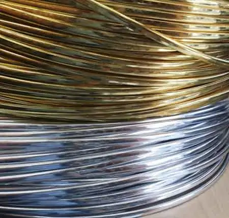
One of the most widely used conductor of electricity is copper. Copper is an excellent conductor of electrical current due to its high conductivity and low electrical resistance. As a result, copper wires are commonly used to transmit electric power over long distances. Copper is also highly durable, making it ideal for use in applications that require long-term reliability.

Aluminum is another common conductor of electrical current. It is cheaper and lighter than copper, which makes it an attractive option for electrical transmission lines. However, aluminum has a lower conductivity than copper, meaning more aluminum is needed to carry the same electric current as copper. This can lead to increased costs for larger electrical applications.

Silver is the best conductor of electrical current known to man. It has the highest electrical conductivity of any metal and is more conductive than copper. However, silver is much more expensive than copper and is only used in applications where its superior conductivity is required.

Gold is also an excellent conductor of electrical current, but it is even more expensive than silver. As a result, gold is mainly used in high-tech applications, such as electronics and aerospace, where its high conductivity and resistance to corrosion are critical.

Nickel is another metal that is a good conductor of electrical current. As a result, it is commonly used in electrical heating applications, such as in electric ovens and toasters.

A material's conductivity measures how easily it allows electric charge to flow through it. Conductivity is affected by several factors, such as the material's composition, temperature, and impurities. Pure water is an example of a poor conductor of electrical current since it contains very few free electrons.

Conductors are distinguished from insulators, which are materials that do not allow electric charge to flow through them. Rubber and plastic are good insulators that cover wires and cables to prevent electrical shock.

Electrical resistance measures a material's opposition to the flow of electric current. The resistance of a conductor depends on the material's composition, temperature, and length. In addition, Ohm's law states that the current through a conductor between two points is directly proportional to the voltage across the two points. For a deeper dive, this guide to electrical resistance explains the underlying physics and units. You can also review the resistance formula to see how voltage, current, and resistance interrelate in practice.


What are the 3 types of conductors?

Metallic conductors: Metallic conductors are materials made of metal that can conduct power. They contain free electrons not bound to any particular atom and can easily move through the metal lattice. Copper, aluminum, silver, gold, and nickel are some examples of metallic conductors.

Electrolytic conductors: Electrolytic conductors are solutions that can conduct due to the presence of dissolved ions. These solutions are typically made of an electrolyte and a solvent. Examples of electrolytic conductors include solutions of salt, acid, and base.

Semiconductor conductors: Semiconductor conductors are materials that have electrical conductivity between the conductors and insulators. They are used in electronic devices such as transistors, diodes, and solar cells. Some common semiconductor materials include silicon, germanium, and gallium arsenide.


What is the main conductor?
Copper is the most commonly used conductor due to its high electrical conductivity and low electrical resistance. It is also highly durable, making it ideal for use in applications that require long-term reliability. For example, copper wires are commonly used in power distribution systems to transmit electric power over long distances.


What properties does a conductor have?

In addition to high electrical conductivity and low electrical resistance, conductors also have high thermal conductivity, meaning they can transfer heat efficiently. In addition, they have low melting points, allowing them to be easily molded and shaped. Conductors are also ductile, easily drawn into thin wires without breaking.


What makes a good conductor of electricity?

A good conductor of electricity has a high number of free electrons available for conducting an electric charge. It also has low electrical resistance, meaning that it does not impede the flow of electric charge. In general, metals make good conductors of power because they have a high number of free electrons.


How does a conductor conduct electricity?

When a conductor is connected to a source of electric charge, such as a battery, the electric field causes free electrons in the conductor to move in the direction of the field. This movement of free electrons creates an electric current, the flow of electric charge.


What are some examples of good conductors?

Some examples of good conductors include copper, aluminum, silver, gold, and nickel. These metals have many free electrons and low electrical resistance, making them ideal for conducting an electric charge.


What is the difference between a conductor and an insulator?

The main difference between a conductor and an insulator is that a conductor allows an electric charge to flow with little or no resistance. In contrast, an insulator does not allow electric charge to flow. Insulators are typically used to cover or insulate conductors to prevent electric shock or keep the electric charge within a circuit. For a formal definition that complements this comparison, consult a concise conductor definition for precise terminology.


What is the role of a conductor in an electrical circuit?

The role of a conductor in an electrical circuit is to provide a path for the flow of electric charge. In addition, conductors connect the different components of an electrical circuit, such as resistors, capacitors, and inductors. They also transmit electric power from one place to another through power lines. For component selection context, see common types of resistors that conductors connect within practical circuits.


What is the importance of conductivity in electrical systems?

Conductivity is an essential property of materials used in electrical systems because it determines how easily an electric charge can flow through a material. Materials with high conductivity are used in applications where efficient transmission of electric power is required, such as in power distribution systems. Conversely, materials with low conductivity are used as insulators to prevent the flow of electric charge.


How does the thickness of a conductor affect its ability to conduct?

The thickness of a conductor affects its ability to conduct electrical current because thicker conductors have a lower electrical resistance. This means thicker conductors can carry more electric current with less power loss due to resistance. For example, a thin copper wire may not be able to have as much current as a thicker copper wire of the same length due to the increased resistance of the thinner wire. Therefore, the thickness of a conductor is an essential consideration in designing electrical circuits, especially for high-current applications where minimizing power loss due to resistance is critical. Additionally, thicker conductors are more durable and less likely to break under stress, making them more suitable for applications where mechanical stress is present, such as bridges and buildings.
  If these tradeoffs are new to you, this primer on electrical resistance connects cross-sectional area to current flow with clear examples.


Related Articles

Related News

Hydroelectricity Explained

Hydroelectricity converts hydropower into grid-ready electricity using dams, penstocks, turbines, and generators, enabling renewable baseload, pumped storage, high efficiency, and low emissions for resilient power systems with load balancing, frequency regulation, and strong capacity factors.


What Is Hydroelectricity?

Hydroelectricity is electricity generated by water turning turbines at dams, delivering low-carbon power to the grid.

✅ Converts hydraulic head and flow into alternating current.

✅ Uses synchronous generators, excitation, and step-up transformers.

✅ Supports grid inertia, regulation, and pumped-storage balancing.


Hydroelectricity is another term for power generated by harnessing the power of damming rivers and moving water into generating plants. Not necessarily falling water, just moving water. There are many famous such Hydroelectricity stations in the world, not the least of them at Niagara Falls, Grand Coulee and Boulder Dam and the three gorges dam in China . In the past, small plants produced electric hydroelectricity. Now, they are massive in size and generation capcity as well as having large reservoirs. If there is a need for power electrical generation stations situated close to the point of consumption is ideal. These are just a few of the many examples of energy produced by falling water. On the other hand, a small mill set in the rapids of a fast-moving stream is also an example of it in action, on a lesser scale. The truth is that any steady current of flowing water from a river or other waterway can be converted to power. Of all the sources electricity from hydroelectricity, dammed reservoirs is one of the cleanest possibe ways to generate electricity to a million people, compared with nuclear power. For broader background on water safety and power concepts, the guide on water and electricity explains interactions, risks, and basic generation principles.


How is HydroElectricity Generated?

Hydroelectricity is generated or "manufactured" in large hydroelectric plants, (electrical generating stations) using the same basic principle as a small grist mill yet on a much larger and vastly improved scale for better efficiency, using pumped storage. These power plants contain electrical generators which are attached to massive turbine devices which spin at great speeds as a result of water rushing through them. These pump water power station turbines are much more efficient at extracting the kinetic energy from the moving water and converting that energy it into electrical production through these generators. To see how hydro fits within the wider energy landscape, review how electricity is generated across different prime movers and grid systems.

The amount of electricity from Hydroelectricity extracted from water as an energy source depends not only on the capacities of volume sent through a hydroelectric power plant but on the difference in height between the source and the water's outflow. This height difference is called the head. The amount of potential energy in water is directly proportional to the head and how much water is released. To obtain very high head, water for a hydraulic turbine may be run through a large pipe called a penstock. These relationships between flow, head, and output are core electricity generation principles that guide plant design and optimization.

For instance, energy is derived to make electricity water has to move from a higher elevation to a lower elevation through a large tube" otherwise known in technical terms as a "penstock". When the water reaches the end of the penstock, it turns a water wheel or "turbine" at enormous speeds. The turbine rotates, via a connected shaft to an electrical generator, and this generator creates electricity. It is the turbine and generator working in combination that converts "mechanical energy" into "electric energy". The water that makes this possible, is a renewable energy resource, just like the wind that turns the turbine attached to a generator. This mechanical-to-electrical conversion is a classic way to generate electricity efficiently when hydraulic conditions are favorable.

Hydroelectricity may be extracted from water but it depends not only on the volume of water but also on the difference in height between the top of the penstock and where the water spins the turbine. This difference in height is often referred to as the "head". From this "head", it can be determined the exact amount of potential energy that can be converted. Therefore, it is advantageous to build power dams as high as possible to convert the maximum energy from mechanical energy. Project planners evaluate head, flow duration, and dispatch needs in the context of overall electricity production targets and grid reliability.

While many hydroelectricity generating stations supply world power grids, some projects are created for private business purposes. For example, aluminium manufacturing companies require large amounts of power. And there are many other examples of industries that use hydroelectricity in their manufacturing operations. Industrial facilities often diversify procurement among various sources of electricity to balance costs, resilience, and sustainability goals.

While hydroelectricity in the United States seems relatively clean and safe in comparison to burning fossil fuels (coal or oil or natural gas), nearly all large hydroelectricity installations in North America have significant had impacts on nearby environmental habitats once they are brought online. This is because they significantly impede the flow of water in rivers and lakes at the point where the generating dam is installed In turn, this causes significant increases in water levels in corresponding upstream water systems while at the same time creating much lower water levels downstream. Mitigation strategies may include fish passages, adaptive flow management, and complementary alternative electricity options to reduce ecological disruption.


Related Articles

View more

Kirchhoff's Law

Kirchhoff's Law, comprising the Current Law (KCL) and Voltage Law (KVL), governs electrical circuits by ensuring charge conservation and energy balance, essential for analyzing current flow, voltage drops, and network behaviour.


What is Kirchhoff's Law?

Kirchhoff's law is an essential principle in the analysis of electrical circuits, enabling a comprehensive understanding of the behaviour of complex circuits.

✅ Defines relationships between currents and voltages in electrical circuits

✅ Ensures conservation of charge (KCL) and energy (KVL) in networks

✅ Essential for analyzing and solving complex circuit problems

It consists of two fundamental rules, Kirchhoff's Current Law (KCL) and Kirchhoff's Voltage Law (KVL), which are intrinsically linked to other electricity laws, such as Ohm's law.  Kirchhoff’s Law works closely with Ohm’s Law Formula to calculate voltage drops, currents, and resistance in electrical networks.

Kirchhoff's Current Law (KCL) - Also known as the first Kirchhoff's law or Kirchhoff's junction rule, KCL states that the sum of the currents entering a junction in a circuit is equal to the sum of the currents leaving the junction. Mathematically, it can be expressed as:

ΣI_in = ΣI_out

KCL is based on the principle of the conservation of charge, asserting that charge can neither be created nor destroyed. In practical terms, KCL means that, at any given point in a circuit, the total current entering must equal the total current leaving, ensuring a continuous flow of electric charge. Understanding Basic Electricity provides the foundation for applying Kirchhoff’s Current Law and Voltage Law to real-world circuit analysis.

Kirchhoff's Voltage Law (KVL) - Also known as the second Kirchhoff's law or Kirchhoff's loop rule, KVL states that the sum of the voltage gains and losses (potential differences) around any closed loop in a circuit is zero. Mathematically, it can be expressed as:
ΣV_rise = ΣV_drop

KVL is based on the principle of the conservation of energy, indicating that energy cannot be created or destroyed but can only be converted from one form to another. In electrical circuits, KVL implies that the total voltage supplied in a loop equals the total voltage drop across all components, ensuring that energy is conserved. Accurate circuit calculations require a clear grasp of Electrical Resistance and how it impacts voltage distribution across components.


Relation to Other Electricity Laws

The most significant connection between Kirchhoff's and other electricity laws is Ohm's law, which defines the relationship between voltage, current, and resistance in an electrical circuit. Ohm's law can be expressed as:

V = IR

When analyzing a circuit using Kirchhoff's laws, Ohm's law is often employed to calculate unknown quantities such as voltage drops, currents, or resistance values. By combining Kirchhoff's laws with Ohm's law, a complete understanding of the behaviour of electrical circuits can be achieved, facilitating efficient design, troubleshooting, and optimization. Applying Kirchhoff’s principles is easier when you understand key Electrical Terms used in engineering and troubleshooting.


History

Gustav Robert Kirchhoff, a German physicist, made significant contributions to understanding electrical circuits by establishing two fundamental laws: Kirchhoff's Voltage Law (KVL) and Kirchhoff's Current Law (KCL). These laws are essential tools for circuit analysis, enabling engineers to design and troubleshoot electrical networks efficiently. In addition to resistance, Capacitance plays a vital role in determining circuit behavior, especially in AC systems.

KVL, also known as the loop rule, states that the algebraic sum of all the voltages around a closed loop equals zero. This principle is derived from the conservation of energy, which ensures that no energy is lost within a closed system. In essence, KVL states that the energy supplied to a circuit is equal to the energy consumed by the components in that circuit. Therefore, when solving problems using KVL, it is essential to consider voltage drops across resistive elements like resistors and voltage rises due to sources like batteries or generators.

On the other hand, KCL, or the junction rule, states that the algebraic sum of currents entering a junction (node) in a circuit is equal to the sum of currents leaving the same junction. This law is a consequence of the conservation of charge, which posits that charge cannot be created or destroyed within an electrical circuit. KCL ensures that the total charge entering and leaving a node remains constant, with the currents (I1, I2, I3, I4, I5) balancing each other. Knowledge of Voltage Drop is essential when using KVL to assess energy losses in electrical circuits.

The significance of these laws in electrical networks lies in their versatility, as they can be applied to a wide range of circuits, from simple series and parallel circuits to more complex electrical networks. Kirchhoff's laws can be employed in conjunction with Ohm's Law, which states that the current through a conductor is proportional to the voltage across it and inversely proportional to its resistance. Using Kirchhoff's and Ohm's Law, engineers can analyze various aspects of a circuit, including voltage drops, current flow, and power distribution.

When analyzing series and parallel circuits, his laws offer valuable insight into the behaviour of electrical components. In series circuits, the current remains constant throughout the entire loop, while the voltage drops across each resistor are proportional to their respective resistances. The voltage across each branch is constant in parallel circuits, but the current is divided among the parallel resistors according to their resistances. By applying KVL and KCL to these configurations, engineers can determine the optimal arrangement of components for a given application.

To illustrate the application of his laws, consider a simple example. Imagine a circuit with a battery, two resistors in series, and a capacitor in parallel with the second resistor. By applying KVL and KCL, we can determine the voltage drop across each resistor, the current flow through each branch, and the voltage across the capacitor, enabling us to analyze the circuit's behaviour under various conditions.

Despite their usefulness, his laws have some limitations and assumptions. For instance, they assume that the components in a circuit are ideal, meaning they have no internal resistance or capacitance. Additionally, they don't account for the effects of electromagnetic fields or the finite speed of signal propagation in AC circuits. However, these limitations are often negligible in many practical applications, as they only marginally impact circuit performance. For a deeper historical context, explore the History of Electricity and the contributions of Gustav Kirchhoff to modern circuit theory.


Related Articles


View more

Voltage Drop Calculator

A voltage drop calculator helps electricians and engineers estimate line loss, wire size, and circuit efficiency. By inputting conductor length, current, and material, it ensures proper electrical design, safe voltage regulation, and compliance with power distribution standards.


What is a Voltage Drop Calculator?

A voltage drop calculator (VDC) is crucial for any electrical engineer or designer. It enables them to calculate VD accurately, which is essential for maintaining an efficient and safe electrical system.

✅ Quickly estimates voltage loss in electrical circuits

✅ Helps select the correct wire size for load and distance

✅ Supports NEC code compliance and system efficiency


Power Quality Analysis Training

Power Factor Training

Request a Free Power Quality Training Quotation

Voltage drop calculators are used in various applications, including residential, commercial, and industrial settings, and offer several benefits, such as accurate calculations, time savings, cost reduction, and hazard prevention. Additionally, engineers can ensure the electrical system operates efficiently and safely by considering factors such as cable sizing, wire gauge, and the type of conductor used. Want the full math? Visit our voltage drop formula guide for detailed equations and examples.

There are numerous VDCs available on the internet, and one of the best places to find them is on Google Play.


Applications of Voltage Drop Calculators

VDCs are used in various residential, commercial, and industrial applications. For instance, in residential applications, VDCs help determine the appropriate wire size for the electrical service panel, the length of wires, and the type of installation, ensuring that the electrical system operates correctly and safely. Additionally, VD formulas can be used to calculate resistance and reactance in both single-phase and three-phase electrical systems. It is measured in feet over a specified length.

In commercial applications, voltage drop calculators are used to design and maintain electrical systems in buildings such as hospitals, schools, and offices. These buildings require careful design to ensure that they meet the power requirements of the building and are safe for occupants. VDCs play a crucial role in this process by calculating the VD in the circuit and determining the appropriate wire size and other specifications.

In industrial applications, VDCs are used to design and maintain electrical systems in factories and other industrial settings. These systems require careful design to ensure they meet the equipment's power requirements and are safe for workers. VDCs determine the circuit's VD, the appropriate wire size, and other specifications to ensure that the electrical system operates efficiently and safely. For an overview of the general principles of voltage drop across AC and DC systems, read our article.


Benefits of Using a VDC

Using a VDC offers several benefits, including:

Accurate Calculations: VDCs use complex algorithms to calculate VD accurately. This ensures that the electrical system operates efficiently and safely.

Saves Time: VDCs save time by automating the process of calculating VD. This allows engineers to focus on other aspects of the design process, such as equipment selection and installation.

Reduces Costs: By accurately calculating VD, engineers can select the appropriate wire size and other specifications, thereby reducing the cost of the electrical system.

Prevents Hazards: Accurate calculation of VD prevents electrical hazards, including fires and shocks. 


FREE Voltage Drop Calculator 


Cable Sizing and Wire Gauge

One of the most critical factors to consider when designing an electrical system is cable sizing and wire gauge. The conductor's or wire gauge's size is critical in determining the amount of current that can flow through the conductor without causing excessive VD or overheating. American Wire Gauge (AWG) is the standard system used to specify wire sizes, providing a range of conductor sizes based on the wire's cross-sectional area. Additionally, the National Electrical Code (NEC) provides guidelines for ampacity and voltage drop (VD) for various conductor sizes and types of installations.


Copper or Aluminum Conductors

The type of conductor used in an electrical system also affects the voltage drop (VD). Copper and aluminum conductors are the most commonly used materials, with copper being preferred due to its lower resistance and higher conductivity. However, aluminum conductors are less expensive and commonly used in larger conductors and power transmission lines.


Frequently Asked Questions


How do I calculate voltage drop?

To calculate VD, you can use the VD formula, which is V = IR, where V is the voltage drop, I is the current flowing through the conductor, and R is the resistance of the conductor. By knowing the current, resistance, and length of the conductor, you can calculate the VD and determine whether it falls within acceptable limits.


How do I use it?

To use a VDC, you need to input the current flowing through the conductor, the length of the conductor, and the wire gauge or cable size. The tool then uses complex algorithms to calculate the VD in the circuit accurately. Based on the results, you can determine the appropriate wire size, cable length, and other specifications necessary to maintain an efficient and safe electrical system.


How is voltage drop calculated in a circuit?

VD is calculated in a circuit using Ohm's Law, which states that the VD across a conductor is equal to the product of the current and resistance. By knowing the current, resistance, and length of the conductor, you can calculate the VD and determine whether it falls within acceptable limits.


What factors affect voltage drop in a circuit?

The factors that affect VD in a circuit include the current flowing through the conductor, the length of the conductor, the resistance of the conductor, and the wire gauge or cable size. Other factors, such as the type of conductor and installation, can also affect VD.


Why is it important to calculate voltage drop?

Calculating VD is essential in maintaining an efficient and safe electrical system. VD can impact the performance of electrical equipment and devices, leading to hazards such as fires and electrical shock. By accurately calculating VD, engineers can select the appropriate wire size, cable length, and other necessary specifications to maintain an efficient and safe electrical system.


What are the benefits of using a VDC?

Using a VDC offers several benefits, including accurate calculations, time savings, cost reduction, and hazard prevention. By accurately calculating VD, engineers can select the appropriate wire size and other specifications, thereby reducing the cost of the electrical system. In addition, calculating VD accurately can prevent electrical hazards such as fires and shocks.


Are there any limitations to using a VDC?

While VDCs offer numerous benefits, they also have some limitations. For example, they rely on the accuracy of the input parameters, but may overlook other factors that can affect voltage drop, such as temperature and ambient conditions. Additionally, they may not be suitable for complex electrical systems.


What is the voltage drop per 100 ft?

The VD per 100 ft depends on various factors, including the current flowing through the conductor, the conductor's length, its resistance, and the wire gauge or cable size. Therefore, it is essential to calculate the VD accurately to determine the appropriate wire size and cable length necessary to maintain an efficient and safe electrical system.


What is a rule of thumb for voltage drop?

The rule of thumb for VD is that the VD in a circuit should not exceed 3% for power circuits and 5% for lighting circuits. These values are based on the National Electrical Code (NEC) guidelines, ensuring the electrical system operates efficiently and safely.

Southwire Voltage Drop Calculator


Related Pages


View more

Electricity and Electrical Energy

Electricity powers modern engineering, driving circuits, voltage, current, and AC/DC power systems for transmission, distribution, and control. Engineers analyze resistance, impedance, and frequency, optimize grids, and integrate renewables with transformers, generators, and smart controls.


What Is Electricity?

Electricity is the flow of charge enabling energy conversion, signal transmission, and power control across circuits.

✅ Quantified by voltage (V), current (A), and power (W)

✅ Governed by Ohm's Law, Kirchhoff's Laws, and Maxwell's equations

✅ Transmitted via grids using AC, transformers, and protection


Electricity is a manufactured product. It is not something you pump out of the ground or mine or collect from the sun or wind. For a clear primer on definitions and units, visit what electricity is to ground these ideas.

Electric power is manufactured from a rotating machine that we call an electrical generator. After it is generated, (manufactured) it is then delivered through copper wires to where it is utilized If you want to see how turbines and alternators convert motion into power, explore the electricity generator to understand key components and operation.

Electricity - most people don't understand what it is. They just turn on the light switch or start the appliance or push the button and something works. It's only when there is no electric power available that we start to consider the importance of it in our daily personal and working lives. A step-by-step explanation of fields, voltage, and current is outlined at how electricity works for readers new to the topic.

But the invention of the machine to generate power is right next to the invention of the printing press in the list of major contributions to the advancement of human civilization. For context on pioneers from Faraday to Tesla, review who invented electricity to connect invention with modern grids.

Without it, we would be burning wood and coal to heat our homes and businesses and using oil and candles to light our way in the dark. That is the way it was for humans civilization for countless centuries. Only since the invention of the electric generator have humans been able to advance in every aspect of modern life. In fact, modern living is defined by electric power. This shift from fuels to electrons is traced in the history of electricity to show how infrastructure reshaped society.

We have assembled a series of pages in our web site to help you to understand the business of electricity - how it works and how it is used. To dive deeper into fundamentals before the business aspects, start with electricity: how it works for a concise technical overview.

We hope that you can use this information to better understand the technology and issues behind the manufacturing of electric power. Further reading on thermal, hydro, and renewable pathways is available at how electricity is generated to see how manufacturing methods compare.


Related Articles

View more

Electricity Grid - T&D

Electricity grid infrastructure delivers power through transmission lines, substations, and smart grid controls, balancing voltage and frequency, integrating renewable energy, enabling demand response, improving reliability, and supporting utilities with real-time monitoring and load management.


What Is the Electricity Grid?

A network of transmission, distribution, and control systems that delivers reliable electrical power to consumers.

✅ Transmits high-voltage power from plants to local networks

✅ Steps down voltage at substations for safe distribution

✅ Integrates renewables with smart grid and demand response


The electricity grid is a complex and essential component of modern society. It provides the power necessary to operate homes, businesses, and industries, and it is constantly evolving to meet the demands of a changing world. From power generation to distribution, transmission lines to load balancing and renewable energy integration, every component is critical in ensuring we can access reliable and affordable energy whenever needed. For a broader primer, resources such as electric power systems outline how these elements interconnect in practice.

At its core, the grid is a system that connects power generation facilities to consumers through transmission lines and distribution systems. It is designed to move electricity from where it is generated to where it is needed, whether in a residential home or a large industrial facility. The term "grid" refers to the interconnectedness of these systems, which allows power to flow from one location to another as needed. The federal energy regulatory commission ferc regulates the grid.

In North America, the transmission and distribution (T&D) grid is managed by federal, state, provincial, and territorial agencies. The grid is divided into various regions, each with its grid operator responsible for ensuring reliable and efficient operation within their respective jurisdiction. For instance, Canada's power delivery network is divided into four main regions: Western Canada, Ontario, Quebec, and the Atlantic region. Similarly, the United States' electricity grid is divided into three major interconnected systems: the Eastern Interconnection, Western Interconnection, and the Electric Reliability Council of Texas (ERCOT) system. Each region's grid operator works closely with neighbouring grid operators to ensure a seamless flow of electrical power across the interconnected grid, even during periods of high demand or unexpected outages.

The power delivery network can be broken down into three main components: power generation, transmission, and distribution. Power generation facilities can take many forms, including coal-fired, natural gas, nuclear, and renewable energy sources such as wind and solar. These facilities generate electrical power transmitted over high-voltage transmission lines to substations, where the voltage is lowered for distribution to homes and businesses through a network of distribution lines. For those new to supply technologies, overviews of how electricity is generated cover conventional and renewable pathways.

Transmission lines are a critical component of the T&D system, which deliver and produce electricity at higher voltages. T&D provides the means to move large amounts of electrical power over long distances. These lines are typically made of high-strength steel or aluminum and span hundreds of miles. They are also designed to be highly resilient to extreme weather events such as hurricanes, tornadoes, and ice storms. Understanding ratings, capacity, and losses draws on electricity power fundamentals that inform planning and operations.

The distribution system is the final component of the power grid, responsible for delivering electrical power directly to homes and businesses. This system includes transformers, power lines, and meters, which work together to regulate power flow to individual consumers. The distribution system also includes local power generation facilities, such as rooftop solar panels and small-scale wind turbines, which can supplement the power provided by the grid. To see how fuel mixes influence local grids, summaries of sources of electricity highlight regional differences.

As the world increasingly relies on electrical power, there is a growing need to modernize and upgrade the power delivery network to meet the demands of the 21st century. One approach to this is the development of a smart grid, which uses advanced sensors, communication networks, and analytics to optimize the flow of power and improve reliability. Another approach is the integration of renewable energy sources such as wind and solar into the grid, which can reduce greenhouse gas emissions and improve grid resilience. Advanced planning and forecasting increasingly leverage power system analysis to evaluate contingencies and optimize investments.

Load balancing is another critical function, ensuring that real-time power generation and consumption are matched. This is accomplished through a combination of forecasting, automated control systems, and energy storage facilities such as batteries and pumped hydroelectric storage. In flexible markets, insights into electricity generation help operators schedule resources effectively.

Reliability and resilience are also crucial factors in its overall performance. The grid must be designed to withstand extreme weather events and other disruptions, such as cyberattacks or equipment failures. This requires a combination of robust engineering and effective emergency response planning.


What is an electricity grid, and how does it work?

A T&D system is a complex network of power generation facilities, transmission lines, and distribution systems that work together to ensure reliable and affordable energy is available to consumers. At its core, the grid is a system that connects power generation facilities to consumers through transmission lines and distribution systems. It is designed to move electrical power from where it is generated to where it is needed, whether in a residential home or a large industrial facility. The grid uses high-voltage transmission lines to move electrical power over long distances, then lowers the voltage through transformers for distribution to homes and businesses. For foundational clarity, a concise explainer on what electricity is helps connect basic concepts to grid operations.


What is the difference between the transmission and distribution systems?

The transmission system is responsible for moving large amounts of electrical power over long distances at high voltages. This is accomplished through a network of high-voltage transmission lines and substations spanning hundreds of miles. The distribution system delivers electrical power directly to homes and businesses at lower voltages. This system includes transformers, power lines, and meters, which work together to regulate the flow of electricity to individual consumers.


How is renewable energy integrated?

Renewable energy sources such as wind and solar are integrated into the T&D system through a process called interconnection. This involves connecting the renewable energy source to the grid through a substation and transformer, ensuring that the energy generated can be transmitted to consumers. Renewable energy sources can also be connected to the grid through distributed generation, where energy is generated on-site at the point of consumption, such as through rooftop solar panels.


What are the challenges associated with maintaining the reliability and resilience of the T&D system?

Maintaining reliability and resilience is a complex task requiring robust engineering and effective emergency response planning. Some of the challenges associated with this include extreme weather events, cyberattacks, equipment failures, and natural disasters. In addition, as the grid becomes more reliant on renewable energy sources, new challenges may arise related to load balancing and energy storage.


What is a smart grid, and how does it differ from a traditional T&D system?

A smart grid is a modernized version of the traditional T&D system that uses advanced sensors, communication networks, and analytics to optimize the flow of electrical power and improve reliability. Unlike a traditional T&D system, designed to move electrical power from power plants to consumers, a smart grid enables two-way communication between consumers and the grid. This allows for greater control and flexibility in managing energy usage and improved efficiency and reliability.


How can energy storage be used to support the T&D system?

Energy storage can be used to support the T&D system in several ways. One essential function is to provide backup power in the event of a blackout or other disruption to the grid. Energy storage can also help balance the load on the grid, ensuring that power generation and consumption are matched in real-time. In addition, energy storage can help integrate renewable energy sources into the grid by storing excess energy for use during times of low generation.


What is grid modernization, and why is it important for the future of the T&D system?

Grid modernization refers to upgrading and improving the T&D system to meet the demands of a changing world. This may involve the development of a smart grid, the integration of renewable energy sources, and the deployment of advanced sensors and control systems. Grid modernization is important for the future of the T&D system because it will enable greater efficiency, reliability, and sustainability while ensuring that the grid is resilient to emerging threats and challenges.


Related Articles

View more

Electric Power Systems

Electric power systems manage generation, transmission, and distribution across grids and substations, using protection relays, SCADA, and control systems to ensure reliability, stability, power quality, and efficient load flow with renewable integration.


What Are Electric Power Systems?

Networks that generate, transmit, and distribute power, ensuring reliability, stability, and efficient grid operation.

✅ Includes generation, transmission, distribution, and substations.

✅ Uses protection, SCADA, and controls for reliability and safety.

✅ Integrates renewables with load flow, stability, and demand forecasting.


Electric power systems have evolved significantly in recent years, driven by the increasing demand for clean and sustainable energy sources. Advancements in renewable energy integration, smart grid technology, energy storage, and microgrids are transforming how we generate, transmit, and consume electricity. In addition, as the world continues to face the challenges of climate change and security, developing and implementing these technologies are essential for building a more sustainable and resilient future. Readers new to core concepts can review what electricity is to connect these technologies with fundamental principles.


The main components of an electric power system include generation, transmission and distribution, and load management. Generation refers to producing energy from various sources such as fossil fuels, nuclear and renewable energy. Renewable electrical energy sources, like solar, wind, and hydro, are increasingly being integrated into electric power systems to reduce dependence on fossil fuels and decrease greenhouse gas emissions. However, integrating renewable energy sources requires advanced technologies and strategies to maintain grid stability. For a concise survey of primary resources, see major sources of electricity for additional context on resource mixes. Those interested in the conversion processes can explore how electricity is generated to understand key methods and tradeoffs.

One such technology is the smart grid, an intelligent network that uses digital communication technology to monitor and control the flow of electricity. Smart grids enable better integration of renewable sources by managing their intermittent nature and ensuring grid stability. Additionally, smart grids facilitate demand response, a mechanism that encourages consumers to adjust their consumption based on real-time price signals, ultimately leading to more efficient use of resources. For system-level context on grid architecture, the overview at electricity grid basics explains how modern networks coordinate supply and demand.

Energy storage plays a crucial role, particularly in renewable integration. By storing excess energy generated during periods of low demand, energy storage systems can help balance supply and demand, improve grid stability, and reduce the need for additional generation plants. Some common energy storage technologies include batteries, pumped hydro, and flywheels. For background on production metrics that storage helps smooth, consult electricity production data to see how output varies across time.

Microgrids, small-scale systems that can operate independently or in conjunction with the main grid, contribute to more resilient systems. They often incorporate renewable sources, storage, and advanced control systems to provide a reliable electricity supply, especially during grid outages or emergencies. Microgrids can also reduce losses associated with long-distance electricity transmission and help alleviate stress on the main grid.

Grid stability remains one of the key challenges. The integration of renewable sources and the increasing demand for electricity place significant stress on the existing infrastructure. Solutions for grid stability include advanced control systems, energy storage, and distributed generation. Distributed generation refers to smaller-scale generation units, like solar panels or wind turbines, located closer to the end-users, which can help reduce the burden on the main grid. Engineers use rigorous studies such as power system analysis to evaluate contingencies and design robust operating strategies.

Demand response is managed in modern electric power systems through advanced communication and control technologies. Real-time data on consumption and generation allows utilities to adjust pricing and encourage consumers to shift their usage patterns, helping to reduce peak demand and improve overall system efficiency.

Emerging technologies in electric power systems include single-phase and three-phase power supplies designed to deliver electricity more efficiently and effectively to various types of loads. Single-phase power is typically used in residential settings, while three-phase power is more commonly used in commercial and industrial applications. Innovations in electrical engineering in the United States also drive advancements in transmission and distribution systems, focusing on reducing losses and improving reliability. A broader view of production scaling and plant types is provided in electricity generation overviews that link equipment choices with system performance.


Related Articles

View more

Sign Up for Electricity Forum’s Newsletter

Stay informed with our FREE Newsletter — get the latest news, breakthrough technologies, and expert insights, delivered straight to your inbox.

Electricity Today T&D Magazine Subscribe for FREE

Stay informed with the latest T&D policies and technologies.
  • Timely insights from industry experts
  • Practical solutions T&D engineers
  • Free access to every issue

Download the 2025 Electrical Training Catalog

Explore 50+ live, expert-led electrical training courses –

  • Interactive
  • Flexible
  • CEU-cerified