Electricity Supplier - Make The Right Choice


Electricity Supplier

Electricity supplier delivers power via transmission and distribution networks, managing tariffs, load forecasting, SCADA, and power quality, integrating renewables, smart meters, and demand response to ensure grid reliability, compliance, and efficient kWh billing.


What Is an Electricity Supplier?

An electricity supplier procures and delivers power, manages tariffs, and ensures grid reliability and power quality.

✅ Energy procurement and wholesale market participation

✅ Distribution coordination, SCADA monitoring, and outage management

✅ Tariff design, metering, billing, and power quality compliance


Who is my electricity supplier?

In Canada and the United States, it’s easy to learn which energy provider serves your property or residence. It depends on whether you are trying to find your electricity and natural gas supplier. Sometimes, homes and businesses have the power to choose their energy service utility company and the products and service they provide. Customers are free to choose. It's a competitive energy marketplace. For a plain-language primer on infrastructure, see the electricity supply overview to understand typical delivery steps.

If you use both services, your property might have the same local distribution company for both fuels, – commonly known as a "duel fuel supplier". But if your utility records are stored separately, you might need to more research to learn who supplies your natural gas services and your electricity services separately. If you are curious where the power originates, this guide to how electricity is generated explains common fuel sources and grid integration.


Here is a list of accredited Electricity Suppliers in Canada

https://www.ic.gc.ca/eic/site/mc-mc.nsf/eng/lm00525.html

Market dynamics can vary by province, and recent electricity demand trends in Canada help explain seasonal shifts in offers.


Here is a list of accredited Electricity Suppliers in the United States.

https://www.electricchoice.com/blog/25-top-providers-part-1/

When comparing providers, consult current electricity price benchmarks to contextualize quoted rates.


Who can supply electricity?

All electricity supplier companies must have a licence from the Office of Gas and Electricity Markets (Ofgem). One of the licence conditions is that a  company must produce codes of practice on:

Although the codes of practice are not legally enforceable, they will be useful when negotiating with a company and any breach should be reported to governmental regulatory authorities. Understanding the basics in this introduction to what electricity is can make those obligations clearer.


Choosing an electricity supplier

You can change your company if you wish. If you are considering changing your company you should be aware that the pricing structures, services offered and policies will differ between the different companies.You should carefully check the information and contracts of the competing electricity suppliers, and compare these to your current terms, to make sure that you choose the best deal for your needs. A lot depends on your gas bills or electricity bill, and your location by postal code. You can also estimate bill impacts by applying tips from this guide on how to save electricity while comparing plans.


Dual fuel offers

Dual fuel is the supply of gas and electricity by the same company. Some gas and electricity suppliers are licensed separately by Ofgem to supply customers with both fuels. Some companies will supply both fuels under one contract, while others will give one contract for gas and another for electricity. For households with high usage, reviewing your typical electricity power consumption patterns can reveal whether dual fuel makes financial sense.

Electricity Suppliers who make dual offers will often give a discount off the total bill as they can make administrative savings by issuing combined bills and collecting combined payments. However, this does not necessarily mean that the cost of gas and electricity

  • procedures for complaints
  • payment of bills, arrangements for dealing with arrears and prepayment meters
  • site access procedures
  • energy efficiency advice
  • services for older, disabled and chronically sick people. As part of this code of practice, the company must keep a register of these people and provide services to help those who are blind and partially sighted or deaf or hearing impaired. Especially during a power outage, it is important that these customers are restored asap.The customer may have to pay for some of these services.
    • how you will be charged for your electricity supply. Some companies may make a fixed standing charge and then a unit charge for the amount of electricity used; an company may not make a standing charge, but charge a higher unit price
    • whether different charges apply to different periods during the day
    • if cheaper prices are offered for particular payment methods, for example, if you pay by direct debit
    • what service standards each company is offering, for example, for repairs, extra help for older or disabled customers.All electricity suppliers must keep a list of their customers who ask to be identified as pensioners, chronically sick or disabled.The electricity supplier must tell all its customers that it keeps such a list and give information on how customers can be added to the list
    • the company's policies, for example, on debt and disconnection.


Related News

Electricity Generator

Electricity generator converts mechanical energy to electrical power via electromagnetic induction using a prime mover, alternator, stator, and rotor, delivering regulated AC/DC output, high efficiency, and stable voltage and frequency.


What Is an Electricity Generator?

An electricity generator converts mechanical energy to electric power using electromagnetic induction, AC or DC.

✅ Converts rotational torque into regulated AC or DC output

✅ Uses stator, rotor, and excitation for voltage regulation

✅ Applied in power plants, gensets, microgrids, and renewables


An Electricity Generator can create electricity by converting mechanical energy into electrical current that can be used in electrical systems. Wind turbines house such generators to convert the kinetic energy of wind into power that can feed power grids. involve the production of electrons that are a part of every atom,. Electricity is what results when electrons are flowing through a conductor. Ultimately, all that is needed to generate electricity is a metal wire for a conductor and a catalyst to start the electrically charged electrons flowing. You see, unlike natural gas and other fossil fuels that are mined from the Earth, electricity is a manufactured product. Most generators operated by electric utilties are alternating current (ac) generators but there are still some direct current (dc) generators in existence. For a clear primer on charge, current, and how generators relate to these basics, see what is electricity to ground these concepts.

Alternating current is easily generated by means of a rotating magnet windings in a coil of wire, or by a rotating coil of wire inside a powerful magnet. In either case, the ac appears between the ends of the length of wire. This takes place in an electricity generator, which was invented by Michael Faraday. A portable generator can be used as backup power during a power outage. If you want a step-by-step view of induction and circuit behavior, consult how electricity works for context beyond this overview.

The ac voltage that a generator (motor) can develop depends on the strength of the magnets field, the number of turns in the wire coil, and the speed at which the magnet or coil rotates. The ac frequency depends only on the speed of rotation. Normally, for utility ac, this speed is 3,600 revolutions per minute (rpm), or 60 complete revolutions per second (rps), so that the frequency is 60 Hz. Design choices that set coil turns, flux, and rotational speed are discussed in how electricity is generated with practical examples.

When a load, such as a light bulb or heater, is connected to an ac generator, it becomes more difficult to turn the generator. The more power needed from a generator, the greater the amount of power required to drive it. This is why it is not possible to connect a generator to, for instance, your stationary bicycle, and pedal an entire city into electrification. There's no way to get something for nothing. The electrical power that comes out of a generator can never be more than the mechanical power driving it. In fact, there is always some energy lost, mainly as heat in the generator. Your legs might generate 50 W of power to run a small radio, but nowhere near enough to provide electricity for a household. Realistic scenarios for human power and small prime movers are outlined in generate electricity to help size expectations.

The efficiency of a generator is the ratio of the magnet generate power output to the driving power, both measured in the same units (such as watts or kilowatts), multiplied by 100 to get a percentage. No generator is 100 percent efficient. But a good one can come fairly close to this ideal. Typical loss mechanisms and efficiency ranges across technologies are compared in electricity generation for further reading.

At power plants, the power generators can be huge. Each one can be as big as a house. In a power plant, each electricity generator is driven by a massive turbine. Often, steam drives the turbine, and the steam is obtained via heat derived from natural energy source, like falling water. Capacity factors, fuel choices, and turbine types are covered in electricity production to illustrate real-world plant operation.

There are many different sources of electricity and many different ways electricity can be produced and consumed. For instance, modern wind turbines are explained in electricity windmill with details on siting, capacity, and grid integration.


Related Articles

View more

Hydroelectricity Explained

Hydroelectricity converts hydropower into grid-ready electricity using dams, penstocks, turbines, and generators, enabling renewable baseload, pumped storage, high efficiency, and low emissions for resilient power systems with load balancing, frequency regulation, and strong capacity factors.


What Is Hydroelectricity?

Hydroelectricity is electricity generated by water turning turbines at dams, delivering low-carbon power to the grid.

✅ Converts hydraulic head and flow into alternating current.

✅ Uses synchronous generators, excitation, and step-up transformers.

✅ Supports grid inertia, regulation, and pumped-storage balancing.


Hydroelectricity is another term for power generated by harnessing the power of damming rivers and moving water into generating plants. Not necessarily falling water, just moving water. There are many famous such Hydroelectricity stations in the world, not the least of them at Niagara Falls, Grand Coulee and Boulder Dam and the three gorges dam in China . In the past, small plants produced electric hydroelectricity. Now, they are massive in size and generation capcity as well as having large reservoirs. If there is a need for power electrical generation stations situated close to the point of consumption is ideal. These are just a few of the many examples of energy produced by falling water. On the other hand, a small mill set in the rapids of a fast-moving stream is also an example of it in action, on a lesser scale. The truth is that any steady current of flowing water from a river or other waterway can be converted to power. Of all the sources electricity from hydroelectricity, dammed reservoirs is one of the cleanest possibe ways to generate electricity to a million people, compared with nuclear power. For broader background on water safety and power concepts, the guide on water and electricity explains interactions, risks, and basic generation principles.


How is HydroElectricity Generated?

Hydroelectricity is generated or "manufactured" in large hydroelectric plants, (electrical generating stations) using the same basic principle as a small grist mill yet on a much larger and vastly improved scale for better efficiency, using pumped storage. These power plants contain electrical generators which are attached to massive turbine devices which spin at great speeds as a result of water rushing through them. These pump water power station turbines are much more efficient at extracting the kinetic energy from the moving water and converting that energy it into electrical production through these generators. To see how hydro fits within the wider energy landscape, review how electricity is generated across different prime movers and grid systems.

The amount of electricity from Hydroelectricity extracted from water as an energy source depends not only on the capacities of volume sent through a hydroelectric power plant but on the difference in height between the source and the water's outflow. This height difference is called the head. The amount of potential energy in water is directly proportional to the head and how much water is released. To obtain very high head, water for a hydraulic turbine may be run through a large pipe called a penstock. These relationships between flow, head, and output are core electricity generation principles that guide plant design and optimization.

For instance, energy is derived to make electricity water has to move from a higher elevation to a lower elevation through a large tube" otherwise known in technical terms as a "penstock". When the water reaches the end of the penstock, it turns a water wheel or "turbine" at enormous speeds. The turbine rotates, via a connected shaft to an electrical generator, and this generator creates electricity. It is the turbine and generator working in combination that converts "mechanical energy" into "electric energy". The water that makes this possible, is a renewable energy resource, just like the wind that turns the turbine attached to a generator. This mechanical-to-electrical conversion is a classic way to generate electricity efficiently when hydraulic conditions are favorable.

Hydroelectricity may be extracted from water but it depends not only on the volume of water but also on the difference in height between the top of the penstock and where the water spins the turbine. This difference in height is often referred to as the "head". From this "head", it can be determined the exact amount of potential energy that can be converted. Therefore, it is advantageous to build power dams as high as possible to convert the maximum energy from mechanical energy. Project planners evaluate head, flow duration, and dispatch needs in the context of overall electricity production targets and grid reliability.

While many hydroelectricity generating stations supply world power grids, some projects are created for private business purposes. For example, aluminium manufacturing companies require large amounts of power. And there are many other examples of industries that use hydroelectricity in their manufacturing operations. Industrial facilities often diversify procurement among various sources of electricity to balance costs, resilience, and sustainability goals.

While hydroelectricity in the United States seems relatively clean and safe in comparison to burning fossil fuels (coal or oil or natural gas), nearly all large hydroelectricity installations in North America have significant had impacts on nearby environmental habitats once they are brought online. This is because they significantly impede the flow of water in rivers and lakes at the point where the generating dam is installed In turn, this causes significant increases in water levels in corresponding upstream water systems while at the same time creating much lower water levels downstream. Mitigation strategies may include fish passages, adaptive flow management, and complementary alternative electricity options to reduce ecological disruption.


Related Articles

View more

Resistance in Series Explained

Resistance in series refers to the arrangement of individual resistors in a circuit, where the current flows through each resistor end to end. In this configuration, the total resistance (R) of the circuit is equal to the sum of the individual resistances, also known as the equivalent R.


What is Resistance in Series?

Resistance in series refers to a circuit configuration where resistors are arranged in a single path:

✅ Total resistance is the sum of all resistors in the circuit

✅ The same current flows through each resistor

✅ Voltage divides across each resistor based on its value

To calculate the total R in a series circuit, the individual resistances of each resistor are added together. The formula to calculate the equivalent resistance in a series connection is Rtotal = R1 + R2 + R3 + ..., where R1, R2, R3, and so on, represent the individual resistances of each resistor in the circuit.

Ohm's law also applies to series circuits, where the current through each resistor is the same, but the voltage across each resistor is proportional to its R. The total voltage across the series combination of resistors equals the sum of the voltage drops across each resistor.

It is essential to note that the total resistance in a series circuit is always greater than the resistance of any individual resistor in the circuit, due to the cumulative effect of each resistor's resistance.

On the other hand, resistors connected in parallel result in a parallel circuit. The equivalent R of a parallel circuit is calculated differently from a series connection. Instead of adding the individual resistances, the reciprocal of each R is added, and the resulting value is inverted to obtain the equivalent resistance.


R in Series - Parallel

When you place R-I-S, their ohmic values add up arithmetically to reach the total (or net) R.

We can connect a series of resistors (equal to the sum of the individual resistances of a parallel circuit), all having identical ohmic values, in parallel sets of series networks or series sets of parallel networks. When we do either of these things, we create a series-parallel network that can significantly increase the total power-handling capacity of the network compared to the power-handling capacity of a single parallel resistor.


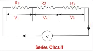
Fig. 4-14. Three resistors in series. 

Sometimes, the total single equivalent R of the combination circuit in a series-parallel network equals the value of any one of the resistors. This always happens if the parallel branches or parallel combinations of the connection components are all identical and are arranged in a network called an n-by-n (or n x n) matrix. That means when n is a whole number, we have n series sets of n resistors connected in parallel, or else we have n parallel sets of n resistors connected in series in the circuit. These two arrangements yield the same practical result for electrical circuits.

A combination of series parallel combinations array of n by n resistors, all having identical ohmic values and identical power ratings, will have n2 times the power-handling capability of any resistor by itself. For example, a 3 x 3 series-parallel matrix of 2 W resistors can handle up to 32 x 2 = 9 x 2 = 18 W. If we have a 10 x 10 array of 1/2 W resistors, then it can dissipate up to 102 x 1/2 = 50 W. We multiply the power-handling capacity of each individual resistor by the total number of resistors in the matrix.

The above-described scheme works if, but only if, all of the resistors have identical ohmic values according to ohms law and identical power-dissipation ratings in terms of total voltage drops when the sum of the voltage drops across each resistor. If the resistors have values that differ even a little bit from one another, one of the components will likely draw more current than it can withstand, so that it will burn out, no matter the voltage source. Then the current distribution in the network will change further, increasing the likelihood that a second resistor will fail, and maybe more.

If you need a resistor that can handle 50 W, and a certain series-parallel connection of the network will handle 75 W, that's fine. But you should not "push your luck" and expect to get away with using a network that will handle only 48 W in the same application. You should allow some extra tolerance, say 10 per cent over the minimum rating. If you expect the network to dissipate 50W, you should build it to handle 55W or a bit more. You don't have to use "overkill," however. You'll waste resources if you cobble together a network that can handle 500W when you only expect it to cope with 50W—unless that's the only convenient combination you can make with available resistors.


Related Articles


View more

Watt’s Law - Power Triangle

Watt’s Law defines the relationship between power (watts), voltage (volts), and current (amps): Power = Voltage × Current. It’s used in electrical calculations to determine energy usage, system efficiency, and safe equipment ratings in both residential and industrial systems.


What is: Watt’s Law?

Watt’s Law is a fundamental principle in electrical engineering:

✅ Calculates electrical power as the product of voltage and current

✅ Helps design efficient and safe electrical systems

✅ Used in both residential and industrial applications

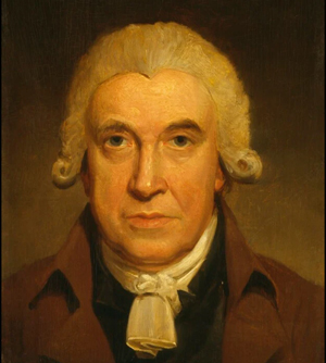
Watt’s Law is a fundamental principle in electrical engineering that defines the relationship between power, voltage, and current in an electrical circuit. James Watt invented the law. It states that the power (measured in watts) of an electrical device is equal to the product of the voltage (measured in volts) and the current (measured in amperes) flowing through it. In other words, the watt's law formula is expressed as: Power = Voltage × Current. This simple equation is essential for understanding how electrical components consume and distribute energy in a circuit. 

For example, consider a light bulb connected to an electrical circuit. The electrical potential (voltage) pushes the electric charge through the filament of the bulb, creating a flow of electrons (current). As the electrons flow, they generate heat and light, representing the bulb’s power in a circuit. By knowing the voltage and current, you can easily calculate the power output of the bulb. The wattage of the bulb indicates the energy consumed per second.

Practical applications of this formula are vast. This equation is especially useful in designing safe and efficient electrical systems. For instance, designing the wiring for both small devices and large power systems requires a thorough understanding of the relationship between voltage, current, and power. The formula helps ensure that systems are capable of delivering the required energy without causing failures or inefficiencies.

Ohm’s Law and this principle are often used together in electrical engineering. While power focuses on the relationship between voltage and current, Ohm’s Law deals with the relationship between voltage, current, and resistance (measured in ohms). Ohm’s Law states that voltage equals current multiplied by resistance (Voltage = Current × Resistance). By combining Ohm’s Law and this power equation, you can analyze an electrical system more comprehensively. For example, if you know the voltage and resistance in a circuit, you can calculate the current and then determine the power in the circuit. To fully understand Watt's Law, it helps to explore how voltage and current electricity interact in a typical electrical circuit.


Georg Simon Ohm – German physicist and mathematician (1787–1854), known for Ohm's Law, relating voltage, current, and resistance.


What is Watt's Law and how is it used in electrical circuits?

Watt’s Law is a fundamental principle in electrical engineering that defines the relationship between power, voltage, and current in an electrical circuit. The formula is expressed as:

Power (Watts) = Voltage (Volts) × Current (Amperes)

In simpler terms, Watt’s Law states that the electrical power consumed by a device (measured in watts) is the product of the electrical potential difference (voltage) and the current flowing through the circuit. Accurate calculations using Watt’s Law often require a voltage-drop calculator to account for line losses in long-distance wiring. Comparing voltage drop and voltage sag conditions illustrates how slight changes in voltage can have a substantial impact on power output.


James Watt – Scottish inventor and mechanical engineer (1736–1819), whose improvements to the steam engine led to the naming of the watt (unit of power).


How is it used? Watt’s Law is widely used to determine the amount of power an electrical device or system consumes. This is especially important for designing electrical circuits, optimizing power distribution, and ensuring the efficiency of devices. Here are a few examples of how it’s applied:

  • Electrical Circuit Design: Engineers use it to calculate the power consumption of devices and ensure that circuits can handle the expected electrical load. This helps prevent overloads and ensures that the wiring is safe.

  • Power Output Calculations: Using this formula, you can calculate the power output of a generator, appliance, or device, enabling you to match the right components to your system's requirements.

  • Energy Efficiency: Understanding power consumption in appliances and devices helps consumers make informed choices, such as selecting energy-efficient options. Devices like wattmeters and watthour meters measure power and energy usage based directly on the principles of Watt’s Law. For a deeper look at how devices like ammeters help measure current, see how their readings plug directly into Watt’s Law calculations.


How is Watt's Law different from Ohm's Law?

Watt’s Law and Ohm’s Law are both fundamental principles in electrical engineering, but they deal with different aspects of electrical systems:

  • Watt’s Law defines the relationship between power, voltage, and current. It focuses on the amount of energy used by a device in a given circuit. The formula is:

           Power = Voltage × Current

  • Ohm’s Law defines the relationship between voltage, current, and resistance in a circuit. Ohm’s Law explains how the current is affected by the voltage and the resistance present in the circuit. The formula for Ohm’s Law is:

            Voltage = Current × Resistance


Key Differences:

  • Focus: It focuses on power, while Ohm’s Law focuses on the flow of electricity in a circuit, particularly how resistance affects current.

  • Watt’s Law is used to determine the amount of power a device is consuming. Ohm’s Law, on the other hand, is used to calculate current, voltage, or resistance in a circuit depending on the other known variables.

  • Applications: It is applied when designing systems that require power management, such as calculating the power output or efficiency of devices. Ohm’s Law is used more in analyzing how current behaves in a circuit when different resistive elements are present.

By combining both laws, electrical engineers can gain a comprehensive understanding of how electrical systems function, ensuring that devices operate efficiently and safely. When used with Ohm’s Law, Watt's Law enables engineers to analyze both energy consumption and electrical resistance.

One key area of application is in energy consumption. By understanding the voltage and current values for a specific device, engineers can monitor the amount of energy the device consumes. This is especially important for managing energy usage in homes, businesses, and power systems. By applying the formula, you can identify inefficient devices and make more informed decisions about energy efficiency.

In renewable energy systems, such as solar panels and wind turbines, this principle plays a critical role in optimizing energy output. Engineers use the formula to calculate how much electrical energy is being generated and distributed. This is crucial for ensuring that power systems operate efficiently and minimize excess energy loss.

Another practical application of this formula is in the automotive industry. It is used to design vehicle charging systems and battery technologies. For example, electric vehicle (EV) charging stations depend on understanding voltage, current, and power to ensure efficient charging times. Engineers use the equation to calculate the charging capacity required for EV batteries, helping to create optimal charging solutions.

In large facilities like data centers, this Watt’s Law formula is used to ensure power distribution is efficient. By applying the relationship between power, voltage, and current, engineers can effectively manage power systems, thereby reducing energy consumption and operational costs. Proper energy management in data centers is crucial, as high power usage can result in significant energy costs.

This power formula is indispensable for electrical engineers and technicians. The applications of Watt’s Law extend across various industries and are utilized in everything from designing power system wiring to developing renewable energy technologies. By combining Ohm’s Law and this principle, electrical engineers can optimize the performance of electrical components, ensuring energy efficiency and system reliability. Understanding the role of a resistor in a circuit can reveal how power is dissipated as heat, a key concept derived from Watt’s Law.

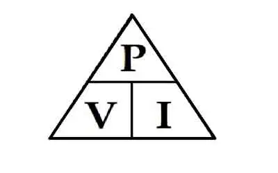
Finally, visual tools like the Watt's Law triangle are often used to simplify the application of this principle, helping both professionals and students understand how to apply the formula. As technology advances and energy demands grow, this formula remains a key element in electrical engineering, guiding the development of more efficient systems for the future.


Related Articles


View more

Electricity Meter

An electricity meter measures electrical energy consumption in homes, businesses, and industries. Also called a power meter or energy meter, it records kilowatt-hours, supports billing, monitors usage patterns, and ensures accurate tracking of electrical load.


What is an Electricity Meter?

An electricity meter is a vital device that utility companies use to measure the amount of electric power consumed by a household or business.

✅ Tracks consumption in kilowatt-hours (kWh) for accurate billing

✅ Monitors load, efficiency, and usage trends over time

✅ Essential for power distribution, energy management, and safety


It provides valuable data that helps both consumers and utility companies monitor power consumption, leading to improved energy management and more accurate billing.


How does an electricity meter work?

It measures the amount of power a household or business consumes, typically in kilowatt-hours (kWh). It records usage over time, allowing utility companies to bill customers accordingly.

Various types exist to suit different applications. The most common include:

  • Electromechanical meters (kWh) with a rotating aluminum disc that measures energy flow.

  • Digital meters that display consumption on an electronic screen.

  • Smart meters are advanced digital devices that automatically transmit usage data to the utility.

Smart meters are central to the smart grid, a modernized system designed to improve the efficiency and reliability of power distribution. With a smart device, consumers can access real-time information about their usage while utilities can implement time-of-use billing to encourage energy conservation during peak hours.


Net Metering & Solar Export Meters

For households with solar panels or other distributed energy sources, net recorders facilitate two-way power flow. They measure both the electrical energy consumed from the grid and the power exported back to it. This enables net metering programs, allowing consumers to earn credits or payments for surplus energy, making the adoption of renewable energy more cost-effective.


Communication & Technology Behind Smart Meters

Smart meters are part of the Advanced Metering Infrastructure (AMI), which utilizes communication networks, including RF mesh, cellular, and power line communication (PLC), to securely transmit usage data to the utility. This connectivity enables demand response programs, remote disconnections, and predictive maintenance, while providing consumers with detailed insights via apps and dashboards.


How do I read my Electricity Meter?

Reading your device may seem complicated, but it’s straightforward:

  • Electromechanical types use dials. Read each from left to right, taking the lower number if the pointer is between two digits.

  • Digital types display readings directly on an LCD screen, often cycling through consumption, demand, and tariff data.
    Some utilities also offer web portals or mobile apps that allow consumers to track their daily or hourly usage.


How can I check if my Electricity Meter is accurate?

To test accuracy, turn off all appliances and observe whether the recorder continues to record consumption. If it does, contact your utility for a professional inspection. Most utilities are required by regulation to maintain meter accuracy within specific tolerances defined by ANSI or IEC standards.

One innovation is the prepaid electricity meter, where consumers pay in advance for power. Once the credit is exhausted, the supply is disconnected until it is recharged. This approach enables households to budget more effectively and promotes conscious energy use.


Security & Privacy in Modern Meters

Electricity meter tampering is a significant concern for utilities. Attempts to reduce recorded consumption can lead to safety hazards and financial losses. Modern recorders include anti-tamper seals, encrypted communication, and intrusion detection to protect data integrity and ensure accurate billing. Utilities also conduct regular inspections to detect and prevent fraud.


What is a Smart Electricity Meter, and how does it differ?

It is a digital device that provides real-time usage data, supports two-way communication, and integrates with the smart grid. Unlike traditional recorders, it enables:

  • Automated reading

  • Dynamic tariffs and demand response

  • Access to consumer dashboards, apps, and alerts

These capabilities enhance billing accuracy, empower consumers to lower their energy costs, and facilitate a more flexible and sustainable grid.


Market Adoption & Trends

Smart meter adoption is growing worldwide. According to industry reports, over 1 billion smart meters have been deployed globally, with continued growth expected in North America, Europe, and Asia. In Canada, utilities like BC Hydro have rolled out smart meters to millions of customers, aiming for more reliable service and reduced outages.


Pros, Cons, and Challenges

Electricity meters offer several clear benefits, including accurate billing, improved energy management, integration with renewable energy sources, and reduced costs associated with manual meter reading. However, challenges include upfront costs, connectivity issues, consumer privacy concerns, and potential inaccuracies if meters drift out of calibration. Addressing these ensures the technology continues to deliver long-term benefits.


The Role of Electricity Meters in Energy Management

Understanding how they work, how to read them, and the different types available helps consumers make informed decisions about their energy usage. By verifying accuracy, adopting advanced technologies such as smart and prepaid meters, and utilizing apps and dashboards, households and businesses can gain greater control over their energy costs.

Ultimately, electricity meters are not just billing devices—they are gateways to improved efficiency, consumer empowerment, and a sustainable energy future.


Frequently Asked Questions


Can I read my smart meter remotely?

Yes. Most enable consumers to view their data via apps or online dashboards provided by their utilities.


How accurate are they?

They must comply with standards like ANSI C12 or IEC 62053, ensuring accuracy within strict tolerances.


What happens if it fails?

If it malfunctions, utilities are legally required to replace it and may use historical usage patterns for interim billing.


Related Articles


View more

Choose The Right Conductor of Electricity

Conductor of electricity describes materials with high electrical conductivity, enabling current flow via free electrons or ions under voltage, such as copper, silver, and aluminum, used in wires, busbars, grounding, and power distribution systems.


What Is a Conductor of Electricity?

A conductor of electricity is a material that easily transmits electric current via free electrons or ions.

✅ Exhibits high conductivity and low resistivity under voltage

✅ Examples: copper, silver, aluminum, graphite, saline water

✅ Enables efficient current flow in cables, busbars, and circuits


A conductor of electricity is a material that allows electric charges to flow through it with little or no resistance. Copper, aluminum, silver, gold, and nickel are some of the most common conductive materials used in electrical engineering. Conductivity is affected by several factors, such as the material's composition, temperature, and impurities. Conductors are distinguished from insulators, which are materials that do not allow electric charge to flow through them. Electrical resistance measures a material's opposition to the flow of electric current. Understanding the properties of conductive materials is essential in designing and operating electrical circuits that power our world. For foundational context, see this overview of electricity to clarify related terms.

The basic principle of a conductor is that it contains free electrons that are not bound to any particular atom. Conductors allow negatively charged electrons to flow easily in an electric field from one atom to another. When a conductor is connected to a source of electric charges, such as a battery, the electrons in the conductor begin to flow in the direction of the electric field. For newcomers, this introduction to conductors expands on how free electrons move under an applied field.

One of the most widely used conductor of electricity is copper. Copper is an excellent conductor of electrical current due to its high conductivity and low electrical resistance. As a result, copper wires are commonly used to transmit electric power over long distances. Copper is also highly durable, making it ideal for use in applications that require long-term reliability.

Aluminum is another common conductor of electrical current. It is cheaper and lighter than copper, which makes it an attractive option for electrical transmission lines. However, aluminum has a lower conductivity than copper, meaning more aluminum is needed to carry the same electric current as copper. This can lead to increased costs for larger electrical applications.

Silver is the best conductor of electrical current known to man. It has the highest electrical conductivity of any metal and is more conductive than copper. However, silver is much more expensive than copper and is only used in applications where its superior conductivity is required.

Gold is also an excellent conductor of electrical current, but it is even more expensive than silver. As a result, gold is mainly used in high-tech applications, such as electronics and aerospace, where its high conductivity and resistance to corrosion are critical.

Nickel is another metal that is a good conductor of electrical current. As a result, it is commonly used in electrical heating applications, such as in electric ovens and toasters.

A material's conductivity measures how easily it allows electric charge to flow through it. Conductivity is affected by several factors, such as the material's composition, temperature, and impurities. Pure water is an example of a poor conductor of electrical current since it contains very few free electrons.

Conductors are distinguished from insulators, which are materials that do not allow electric charge to flow through them. Rubber and plastic are good insulators that cover wires and cables to prevent electrical shock.

Electrical resistance measures a material's opposition to the flow of electric current. The resistance of a conductor depends on the material's composition, temperature, and length. In addition, Ohm's law states that the current through a conductor between two points is directly proportional to the voltage across the two points. For a deeper dive, this guide to electrical resistance explains the underlying physics and units. You can also review the resistance formula to see how voltage, current, and resistance interrelate in practice.


What are the 3 types of conductors?

Metallic conductors: Metallic conductors are materials made of metal that can conduct power. They contain free electrons not bound to any particular atom and can easily move through the metal lattice. Copper, aluminum, silver, gold, and nickel are some examples of metallic conductors.

Electrolytic conductors: Electrolytic conductors are solutions that can conduct due to the presence of dissolved ions. These solutions are typically made of an electrolyte and a solvent. Examples of electrolytic conductors include solutions of salt, acid, and base.

Semiconductor conductors: Semiconductor conductors are materials that have electrical conductivity between the conductors and insulators. They are used in electronic devices such as transistors, diodes, and solar cells. Some common semiconductor materials include silicon, germanium, and gallium arsenide.


What is the main conductor?
Copper is the most commonly used conductor due to its high electrical conductivity and low electrical resistance. It is also highly durable, making it ideal for use in applications that require long-term reliability. For example, copper wires are commonly used in power distribution systems to transmit electric power over long distances.


What properties does a conductor have?

In addition to high electrical conductivity and low electrical resistance, conductors also have high thermal conductivity, meaning they can transfer heat efficiently. In addition, they have low melting points, allowing them to be easily molded and shaped. Conductors are also ductile, easily drawn into thin wires without breaking.


What makes a good conductor of electricity?

A good conductor of electricity has a high number of free electrons available for conducting an electric charge. It also has low electrical resistance, meaning that it does not impede the flow of electric charge. In general, metals make good conductors of power because they have a high number of free electrons.


How does a conductor conduct electricity?

When a conductor is connected to a source of electric charge, such as a battery, the electric field causes free electrons in the conductor to move in the direction of the field. This movement of free electrons creates an electric current, the flow of electric charge.


What are some examples of good conductors?

Some examples of good conductors include copper, aluminum, silver, gold, and nickel. These metals have many free electrons and low electrical resistance, making them ideal for conducting an electric charge.


What is the difference between a conductor and an insulator?

The main difference between a conductor and an insulator is that a conductor allows an electric charge to flow with little or no resistance. In contrast, an insulator does not allow electric charge to flow. Insulators are typically used to cover or insulate conductors to prevent electric shock or keep the electric charge within a circuit. For a formal definition that complements this comparison, consult a concise conductor definition for precise terminology.


What is the role of a conductor in an electrical circuit?

The role of a conductor in an electrical circuit is to provide a path for the flow of electric charge. In addition, conductors connect the different components of an electrical circuit, such as resistors, capacitors, and inductors. They also transmit electric power from one place to another through power lines. For component selection context, see common types of resistors that conductors connect within practical circuits.


What is the importance of conductivity in electrical systems?

Conductivity is an essential property of materials used in electrical systems because it determines how easily an electric charge can flow through a material. Materials with high conductivity are used in applications where efficient transmission of electric power is required, such as in power distribution systems. Conversely, materials with low conductivity are used as insulators to prevent the flow of electric charge.


How does the thickness of a conductor affect its ability to conduct?

The thickness of a conductor affects its ability to conduct electrical current because thicker conductors have a lower electrical resistance. This means thicker conductors can carry more electric current with less power loss due to resistance. For example, a thin copper wire may not be able to have as much current as a thicker copper wire of the same length due to the increased resistance of the thinner wire. Therefore, the thickness of a conductor is an essential consideration in designing electrical circuits, especially for high-current applications where minimizing power loss due to resistance is critical. Additionally, thicker conductors are more durable and less likely to break under stress, making them more suitable for applications where mechanical stress is present, such as bridges and buildings.
  If these tradeoffs are new to you, this primer on electrical resistance connects cross-sectional area to current flow with clear examples.


Related Articles

View more

Sign Up for Electricity Forum’s Newsletter

Stay informed with our FREE Newsletter — get the latest news, breakthrough technologies, and expert insights, delivered straight to your inbox.

Electricity Today T&D Magazine Subscribe for FREE

Stay informed with the latest T&D policies and technologies.
  • Timely insights from industry experts
  • Practical solutions T&D engineers
  • Free access to every issue

Live Online & In-person Group Training

Advantages To Instructor-Led Training – Instructor-Led Course, Customized Training, Multiple Locations, Economical, CEU Credits, Course Discounts.

Request For Quotation

Whether you would prefer Live Online or In-Person instruction, our electrical training courses can be tailored to meet your company's specific requirements and delivered to your employees in one location or at various locations.