Electricity Meter

By Frank Baker, Associate Editor


An electricity meter measures electrical energy consumption in homes, businesses, and industries. Also called a power meter or energy meter, it records kilowatt-hours, supports billing, monitors usage patterns, and ensures accurate tracking of electrical load.


What is an Electricity Meter?

An electricity meter is a vital device that utility companies use to measure the amount of electric power consumed by a household or business.

✅ Tracks consumption in kilowatt-hours (kWh) for accurate billing

✅ Monitors load, efficiency, and usage trends over time

✅ Essential for power distribution, energy management, and safety


It provides valuable data that helps both consumers and utility companies monitor power consumption, leading to improved energy management and more accurate billing.


How does an electricity meter work?

It measures the amount of power a household or business consumes, typically in kilowatt-hours (kWh). It records usage over time, allowing utility companies to bill customers accordingly.

Various types exist to suit different applications. The most common include:

  • Electromechanical meters (kWh) with a rotating aluminum disc that measures energy flow.

  • Digital meters that display consumption on an electronic screen.

  • Smart meters are advanced digital devices that automatically transmit usage data to the utility.

Smart meters are central to the smart grid, a modernized system designed to improve the efficiency and reliability of power distribution. With a smart device, consumers can access real-time information about their usage while utilities can implement time-of-use billing to encourage energy conservation during peak hours.


Net Metering & Solar Export Meters

For households with solar panels or other distributed energy sources, net recorders facilitate two-way power flow. They measure both the electrical energy consumed from the grid and the power exported back to it. This enables net metering programs, allowing consumers to earn credits or payments for surplus energy, making the adoption of renewable energy more cost-effective.


Communication & Technology Behind Smart Meters

Smart meters are part of the Advanced Metering Infrastructure (AMI), which utilizes communication networks, including RF mesh, cellular, and power line communication (PLC), to securely transmit usage data to the utility. This connectivity enables demand response programs, remote disconnections, and predictive maintenance, while providing consumers with detailed insights via apps and dashboards.


How do I read my Electricity Meter?

Reading your device may seem complicated, but it’s straightforward:

  • Electromechanical types use dials. Read each from left to right, taking the lower number if the pointer is between two digits.

  • Digital types display readings directly on an LCD screen, often cycling through consumption, demand, and tariff data.
    Some utilities also offer web portals or mobile apps that allow consumers to track their daily or hourly usage.


How can I check if my Electricity Meter is accurate?

To test accuracy, turn off all appliances and observe whether the recorder continues to record consumption. If it does, contact your utility for a professional inspection. Most utilities are required by regulation to maintain meter accuracy within specific tolerances defined by ANSI or IEC standards.

One innovation is the prepaid electricity meter, where consumers pay in advance for power. Once the credit is exhausted, the supply is disconnected until it is recharged. This approach enables households to budget more effectively and promotes conscious energy use.


Security & Privacy in Modern Meters

Electricity meter tampering is a significant concern for utilities. Attempts to reduce recorded consumption can lead to safety hazards and financial losses. Modern recorders include anti-tamper seals, encrypted communication, and intrusion detection to protect data integrity and ensure accurate billing. Utilities also conduct regular inspections to detect and prevent fraud.


What is a Smart Electricity Meter, and how does it differ?

It is a digital device that provides real-time usage data, supports two-way communication, and integrates with the smart grid. Unlike traditional recorders, it enables:

  • Automated reading

  • Dynamic tariffs and demand response

  • Access to consumer dashboards, apps, and alerts

These capabilities enhance billing accuracy, empower consumers to lower their energy costs, and facilitate a more flexible and sustainable grid.


Market Adoption & Trends

Smart meter adoption is growing worldwide. According to industry reports, over 1 billion smart meters have been deployed globally, with continued growth expected in North America, Europe, and Asia. In Canada, utilities like BC Hydro have rolled out smart meters to millions of customers, aiming for more reliable service and reduced outages.


Pros, Cons, and Challenges

Electricity meters offer several clear benefits, including accurate billing, improved energy management, integration with renewable energy sources, and reduced costs associated with manual meter reading. However, challenges include upfront costs, connectivity issues, consumer privacy concerns, and potential inaccuracies if meters drift out of calibration. Addressing these ensures the technology continues to deliver long-term benefits.


The Role of Electricity Meters in Energy Management

Understanding how they work, how to read them, and the different types available helps consumers make informed decisions about their energy usage. By verifying accuracy, adopting advanced technologies such as smart and prepaid meters, and utilizing apps and dashboards, households and businesses can gain greater control over their energy costs.

Ultimately, electricity meters are not just billing devices—they are gateways to improved efficiency, consumer empowerment, and a sustainable energy future.


Frequently Asked Questions


Can I read my smart meter remotely?

Yes. Most enable consumers to view their data via apps or online dashboards provided by their utilities.


How accurate are they?

They must comply with standards like ANSI C12 or IEC 62053, ensuring accuracy within strict tolerances.


What happens if it fails?

If it malfunctions, utilities are legally required to replace it and may use historical usage patterns for interim billing.


Related Articles


Related News

Electric Power Systems

Electric power systems manage generation, transmission, and distribution across grids and substations, using protection relays, SCADA, and control systems to ensure reliability, stability, power quality, and efficient load flow with renewable integration.


What Are Electric Power Systems?

Networks that generate, transmit, and distribute power, ensuring reliability, stability, and efficient grid operation.

✅ Includes generation, transmission, distribution, and substations.

✅ Uses protection, SCADA, and controls for reliability and safety.

✅ Integrates renewables with load flow, stability, and demand forecasting.


Electric power systems have evolved significantly in recent years, driven by the increasing demand for clean and sustainable energy sources. Advancements in renewable energy integration, smart grid technology, energy storage, and microgrids are transforming how we generate, transmit, and consume electricity. In addition, as the world continues to face the challenges of climate change and security, developing and implementing these technologies are essential for building a more sustainable and resilient future. Readers new to core concepts can review what electricity is to connect these technologies with fundamental principles.


The main components of an electric power system include generation, transmission and distribution, and load management. Generation refers to producing energy from various sources such as fossil fuels, nuclear and renewable energy. Renewable electrical energy sources, like solar, wind, and hydro, are increasingly being integrated into electric power systems to reduce dependence on fossil fuels and decrease greenhouse gas emissions. However, integrating renewable energy sources requires advanced technologies and strategies to maintain grid stability. For a concise survey of primary resources, see major sources of electricity for additional context on resource mixes. Those interested in the conversion processes can explore how electricity is generated to understand key methods and tradeoffs.

One such technology is the smart grid, an intelligent network that uses digital communication technology to monitor and control the flow of electricity. Smart grids enable better integration of renewable sources by managing their intermittent nature and ensuring grid stability. Additionally, smart grids facilitate demand response, a mechanism that encourages consumers to adjust their consumption based on real-time price signals, ultimately leading to more efficient use of resources. For system-level context on grid architecture, the overview at electricity grid basics explains how modern networks coordinate supply and demand.

Energy storage plays a crucial role, particularly in renewable integration. By storing excess energy generated during periods of low demand, energy storage systems can help balance supply and demand, improve grid stability, and reduce the need for additional generation plants. Some common energy storage technologies include batteries, pumped hydro, and flywheels. For background on production metrics that storage helps smooth, consult electricity production data to see how output varies across time.

Microgrids, small-scale systems that can operate independently or in conjunction with the main grid, contribute to more resilient systems. They often incorporate renewable sources, storage, and advanced control systems to provide a reliable electricity supply, especially during grid outages or emergencies. Microgrids can also reduce losses associated with long-distance electricity transmission and help alleviate stress on the main grid.

Grid stability remains one of the key challenges. The integration of renewable sources and the increasing demand for electricity place significant stress on the existing infrastructure. Solutions for grid stability include advanced control systems, energy storage, and distributed generation. Distributed generation refers to smaller-scale generation units, like solar panels or wind turbines, located closer to the end-users, which can help reduce the burden on the main grid. Engineers use rigorous studies such as power system analysis to evaluate contingencies and design robust operating strategies.

Demand response is managed in modern electric power systems through advanced communication and control technologies. Real-time data on consumption and generation allows utilities to adjust pricing and encourage consumers to shift their usage patterns, helping to reduce peak demand and improve overall system efficiency.

Emerging technologies in electric power systems include single-phase and three-phase power supplies designed to deliver electricity more efficiently and effectively to various types of loads. Single-phase power is typically used in residential settings, while three-phase power is more commonly used in commercial and industrial applications. Innovations in electrical engineering in the United States also drive advancements in transmission and distribution systems, focusing on reducing losses and improving reliability. A broader view of production scaling and plant types is provided in electricity generation overviews that link equipment choices with system performance.


Related Articles

View more

Single Line Diagram

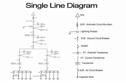
A single line diagram is a simplified representation of an electrical system using single lines and symbols to show components like transformers, circuit breakers, and busbars. It provides a clear overview of power flow and connections.


What is a Single Line Diagram?

A single line diagram is a simplified representation of an electrical power system or electrical grid that shows the flow of electricity through the system.

✅ Simplifies complex electrical power systems into a clear and easy-to-read format.

✅ Identifies components such as generators, transformers, and switchgear.

✅ Helps engineers design, analyze, and maintain electrical distribution networks.


In electrical engineering, a single line diagram is a graphical representation of a circuit or system using standard electrical symbols. These schematics are used in the design, operation, and maintenance of electrical power systems. Principles such as Ampere’s Law and the Biot-Savart Law explain the magnetic effects of current flow that are fundamental to the operation of systems represented in these diagrams.

A single line diagram (SLD) is a vital tool in power engineering, providing a clear representation of how electrical components are interconnected within a system. It illustrates the flow of electricity from the power source through devices like transformers, breakers, and transfer switches, ensuring safe and efficient power distribution. Engineers rely on SLDs to analyze, design, and maintain systems by simplifying complex circuits into easy-to-read schematics. In industrial and commercial settings, these diagrams help identify critical components and streamline maintenance, making them indispensable for modern power engineering applications. Key electrical properties like capacitance and electrical resistance directly influence how energy flows through the components shown in a single line diagram.

A single line diagram is a vital tool in electrical engineering and is used extensively in the design, operation, and maintenance of electrical power systems. They provide a simplified representation of a complex system and are an efficient way to communicate the flow of electricity through the system. Electrical symbols, transformers, circuit breakers, switchgear, and protection systems are all key components of a single line, and their proper representation is crucial for the proper functioning of an electrical power system.


Key Components in a Single Line Diagram

Component Symbol Used Purpose in Power Systems
Transformer Two interlinked coils Steps voltage up or down for efficient transmission and distribution.
Circuit Breaker Rectangle with a line break Protects circuits from overloads and short circuits by interrupting current flow.
Busbar Straight horizontal line Acts as a central point for electrical power distribution within switchgear.
Switchgear Combination of switch icons Houses disconnect switches and protection devices for system control.
Protection System Relay or fuse symbol Detects faults and isolates damaged sections to prevent equipment failure.


Electrical Symbols

Electrical symbols in a single line diagram are used to represent the different components of the electrical system on a single line diagram. These symbols are standardized and used universally in the electrical industry. Some common electrical symbols that can be found include transformers, circuit breakers, switches, busbars and protection systems. Engineers frequently rely on single line diagrams when performing power system analysis, since these schematics simplify complex circuits into clear, manageable visuals.


Power System Components

A power system comprises various components, including generators, transformers, circuit breakers, switchgear, and transmission lines. These components work together to transmit and distribute electrical power. Schematics are used to represent these components in a simplified way.

Electrical distribution is the process of delivering electricity to end-users. Schematics are used to design and plan the distribution network for a specific area. The schematics help identify the components needed to provide power to the area and determine the appropriate rating of the necessary equipment.

The electricity grid is a network of power stations, transmission lines, and distribution networks that supply electricity to end-users. Schematics are used to represent the various components of the electrical grid, and to design and plan the grid. The electrical drawings are also used to monitor and maintain the grid.

Circuit breakers are safety devices that are used to protect electrical circuits from overloading or short circuits. Single lines are used to identify the location of circuit breakers in a power distribution system and to determine their ratings.

Power Transformers are electrical protective devices that are used to increase or decrease the voltage of electrical power. Single lines are used to represent transformers in a system and to determine their ratings.

Load flow analysis is the study of the flow of electrical power through a control system. Single lines are used to study a system's load flow and determine the electrical loads on each component.

Busbars are electrical conductors used to distribute electrical power. Single lines represent busbars in a system and determine their ratings.

Switchgear combines electrical disconnect switches, fuses, and circuit breakers to isolate electrical equipment, ensuring safe operation. Single lines represent switchgear in a system and determine the appropriate ratings.

Protection systems safeguard electrical equipment from damage resulting from overloading or short circuits. Single lines are used to identify a system's protection systems and determine their ratings.


Frequently Asked Questions


What is a simplified representation of an electrical power system?

A single line diagram is a simplified representation of an electrical power system or electrical grid. It illustrates the flow of electricity through the system using a single line diagram and standardized electrical symbols. The schematic is commonly used in the design, operation, and maintenance of electrical power systems.


How is a single line diagram calculated?

It is calculated using load flow analysis. This involves modelling the electrical network and calculating the current and voltage at each point in the system. Load flow analysis is a complex process requiring specialized software and electrical engineering expertise.


What is the main purpose of a single line diagram?

The main purpose is to provide a simplified overview of a power system that can be easily understood by engineers, technicians, and other professionals. The schematic helps identify potential problems in the system and enables efficient design, operation, and maintenance. Accurate diagrams clearly illustrate the movement of active power through breakers, busbars, and switchgear, demonstrating how systems are protected and controlled under various load conditions.


What are some common symbols used in a single-line diagram?

Common symbols in a single-line diagram include transformers, circuit breakers, switches, busbars, and protection systems. These symbols are standardized and used universally in the electrical industry.


Why is it important in power system planning and design?

A single line diagram is crucial in power system planning and design, as it enables engineers to identify potential issues with the system and make informed decisions about equipment sizing, protection systems, and other critical design aspects. The schematic also helps to optimize the system design and improve its efficiency.


How is it used in fault analysis and protection system design?

A single line diagram is used in fault analysis and protection system design. By modelling the electrical network and simulating various fault scenarios, engineers can then design protection systems that quickly detect and isolate faults, minimizing damage to equipment and reducing downtime.


What are the steps involved in creating a single line diagram?

The steps involved in creating a single line diagram include gathering data about the system, modelling the electrical network, selecting appropriate equipment and protection systems, and creating the schematic using specialized software. This process requires expertise in electrical engineering and a deep understanding of power systems.


How can it be used for load flow analysis and system optimization?

A single-line diagram can be used for load flow analysis and system optimization by modelling the electrical network and calculating the current and voltage at each point in the system. This information can then be used to optimize the system design and improve its efficiency.


What are some common mistakes to avoid?

Some common mistakes to avoid when creating a single line diagram include using incorrect electrical symbols, failing to label components clearly, and neglecting to consider all aspects of the system design. It is important to thoroughly understand the system and its components to create an accurate and useful single-line diagram.


Related Articles


View more

Ampere to Ampere Hour Calculator Explained

An ampere to ampere hour calculator converts electric current (amps) to electric charge (Ah) based on time. Multiply current by time in hours to get ampere hours. It's useful for battery capacity, energy storage, and electrical system design.


What is "Ampere to Ampere Hour Calculator"?

An ampere to ampere hour calculator helps convert current flow over time into stored electrical charge.

✅ Multiply current (A) by time (h) to calculate charge (Ah)
✅ Useful for battery sizing and energy storage systems
✅ Supports electrical load and backup power planning


The Ampere to Ampere-Hour Calculator is a useful tool that allows users to estimate the capacity of a battery by converting the current supplied by an electrical device into ampere-hours (Ah). This calculation is particularly important when working with batteries, as it helps determine how long a battery can power a device based on the current it supplies and the device's usage duration. By using this calculator, you can easily convert amps to Ah and estimate the run-time for a specific battery. Understanding how voltage affects battery performance is key, and our voltage guide explains the role voltage plays in ampere-hour calculations. When calculating ampere-hours, it's important to account for voltage drop across conductors, especially in longer circuits. Use our voltage drop calculator to estimate losses and adjust your amp-hour estimations more accurately.


Frequently Asked Questions


What is an Ampere to Ampere Hour calculator, and how does it work?

This calculator helps convert the current, measured in amperes, into Ah capacity, which indicates how long a battery can supply a given current. For instance, a 100ah battery will deliver 100 ampere-hours of charge, meaning it can supply 1 ampere of current for 100 hours, or 10 amperes for 10 hours. To calculate Ah, the formula involves multiplying the current (in amperes) by the time in hours. For example, if a device draws 5 amperes for 20 hours, the result would be 100 ampere-hours. Learn how a watthour meter measures energy over time, complementing ampere-hour readings in power systems.


How do you convert amperes to ampere-hours using a calculator?

To convert amps to Ah, simply multiply the number of amperes by the number of hours the current is expected to flow. This step-by-step method is straightforward:

Ampere Hour (Ah) = Amperes (A) × Time (hours)

For example, a device drawing 5 amps for 10 hours would result in a consumption of 50 Ah. In practical applications, a 100ah battery could theoretically supply 5 amps for 20 hours before running out of charge. By following these steps, users can easily convert Ah to ensure they select the right battery for their needs. A basic understanding of watts law helps you relate amps, volts, and watts to better interpret your battery’s output.


Why is converting amperes to ampere-hours important for battery capacity calculation?

Knowing how to convert amperes to Ah is crucial in determining the capacity of a battery. It enables users to estimate the battery life of a connected device based on its current draw. This information is crucial for selecting the appropriate battery type for various applications, including powering electronic devices, off-grid systems, and backup power sources. A 100 Ah battery might be suitable for low-power consumption devices, while larger systems might require batteries with higher capacities. Knowing what ammeters measure can help you determine current flow before calculating ampere-hours.


What factors should be considered when using an Ampere to Ampere Hour calculator?

When using an Ampere to Ampere Hour Calculator, several factors can affect the accuracy of the results. These include the hour rating of the battery, which defines its capacity over a specific time period, as well as the efficiency of the battery, which can vary depending on the battery type. Additionally, environmental conditions, such as temperature, may affect the battery’s performance. It is also important to avoid common input errors, such as the “error this field is required” message, which can result from incomplete or incorrect data entry.


What are common applications of Ampere to Ampere Hour conversion in electrical systems?

Ah conversions are widely used in battery-powered devices, such as 100ah batteries for solar power systems, electric vehicles, and portable electronics. Calculating the battery Ah capacity is essential for ensuring that a battery can provide sufficient power for the required period. These conversions also help in sizing the battery system correctly and ensuring optimal performance over time. Many industries rely on these calculations for designing and managing power systems.

The Ampere to Ampere Hour Calculator is a valuable tool for converting amperes to Ah and estimating the capacity of a battery. Understanding how to calculate Ah ensures that you select the right battery type for your application, whether it’s powering an electrical device or an entire off-grid system. By considering factors like the hour rating and potential errors, you can make more informed decisions when choosing batteries for long-term use. Explore the concept of what is an ampere to understand the foundation of converting current to amp-hours in any system.


Related Articles


View more

DC Current - Electricity Explained

DC current delivers unidirectional electron flow with constant polarity, powering circuits, batteries, and electronics; characterized by steady voltage, low ripple, and efficient distribution via rectifiers, converters, and regulated power supplies in electrical engineering.


What Is DC Current?

DC current is unidirectional electron flow with constant polarity, providing steady voltage for efficient power delivery

✅ Provides constant voltage for sensitive electronics and logic circuits

✅ Generated by batteries, fuel cells, solar PV; produced via rectification

✅ Enables precise control in motors, sensors, and industrial automation


DC current is essential to electrical energy, powering devices ranging from small electronic gadgets to electric vehicles. We can appreciate its significance in modern life by understanding its properties, applications, and relationship to other electrical concepts such as voltage, resistance, and Ohm's Law. Despite its limitations in power transmission over long distances, the use of DC current in solar energy systems and electric vehicles continues to demonstrate its vital role in an increasingly electrified world. For a practical primer, the direct current overview clarifies key concepts used in everyday systems today.


Direct current (DC) and alternating current (AC) are the two primary forms of current that power various electrical devices and systems. As the name suggests, direct current flows in a single, unidirectional direction, while alternating current oscillates in direction and magnitude. This article will explore the fundamental concepts of DC current, its applications, and its relationship to other aspects of electricity. For deeper contrasts, the difference between AC and DC guide expands on efficiency, safety, and conversion considerations for designers.

It is the flow of electric charge (electrons) in a consistent direction across a conductor, such as a wire. The consistent flow differentiates it from AC, where the direction of the flow periodically reverses. One of the most significant differences between DC and AC current is their power transmission method. DC systems transmit power at a constant voltage, while AC power alternates at a specific frequency. Complementing this, an accessible alternating current explainer details waveform behavior and frequency effects relevant to grid systems.

Electrical circuits using DC current play an essential role in many everyday devices and systems. Some common applications of DC current include batteries, solar panels, and electronic devices. Batteries are a prime example of a DC power source, as they generate a steady flow of electrons from one terminal to another. Solar panels, on the other hand, convert sunlight into DC electrical energy, which can then be stored in batteries or transformed into AC for use in homes or businesses. If you're new to the topic, this current electricity introduction connects sources like batteries and solar arrays to practical loads in simple terms.

In DC current circuits, voltage and resistance are essential factors influencing the flow of electric charge. Voltage refers to the electric potential difference between two points, whereas resistance represents the opposition to the flow of current. Ohm's Law, a fundamental principle in electrical engineering, states that the current flowing through a conductor between two points is directly proportional to the voltage across those points and inversely proportional to the resistance between them. In other words, the higher the voltage or, the lower the resistance, the greater the current. A concise current reference ties these relationships to measurement practices and typical units used in labs.

DC current also plays a critical role in electric vehicles, where it is converted from high-voltage batteries to the required voltage for the electric motor. This conversion from DC to AC is essential because electric motors typically function on AC power.

DC current presents both advantages and disadvantages. One of its main benefits is its simplicity, as it maintains a constant voltage and current flow, making it easier to work with in electronic devices. Additionally, its unidirectional flow allows for more efficient power storage in batteries. However, one significant drawback is that it could be better suited for long-distance power transmission, as it suffers from substantial power loss over long distances.

The story of electricity would be incomplete without mentioning the famous "Battle of the Currents" between Thomas Edison, a staunch advocate of DC systems, and George Westinghouse, who supported AC systems. Ultimately, AC power emerged as the winner for power distribution due to its ability to transmit power over long distances with minimal energy loss. For historical and conceptual grounding, an electricity definition frames how these terms evolved across scientific practice.


DC Current Calculator Explained

A DC current calculator is a tool that helps to determine the direct current flowing through an electrical circuit based on known values of voltage, resistance, and sometimes power. It is used to simplify and verify calculations related to DC circuits and ensure proper circuit design, maintenance, and troubleshooting. The calculator uses Ohm's Law and the power equation as the basis for its calculations.

Ohm's Law states that the current (I) flowing through a conductor between two points is directly proportional to the voltage (V) across those points and inversely proportional to the resistance (R) between them. The formula is:

I = V / R

In addition to Ohm's Law, the power equation can be used to determine the current in a circuit when the power (P) and voltage (V) are known:

P = IV

By rearranging this formula, we can find the current:

I = P / V

To use a calculator, you will typically input the known voltage, resistance, and/or power values, and the calculator will solve for the unknown variable (in this case, the current). For safe circuit operation, some calculators may provide additional information, such as power dissipation or required resistor wattage. If you need a refresher before using calculation tools, this basic electricity primer reviews units, symbols, and safety fundamentals that prevent common mistakes.

A calculator is especially useful for electrical engineers, technicians, and hobbyists working with DC circuits to verify their calculations or diagnose issues within the circuit. It can help ensure the proper functioning of electronic devices, efficient energy usage, and the safety of the electrical components within a system.


Related Articles

View more

Power Factor Explained

Electrical systems depend on efficiency to operate safely and cost-effectively. One key indicator of that efficiency is power factor, which measures how effectively electrical energy is converted into useful work.

Power Quality Analysis Training

Power Factor Training

Request a Free Power Quality Training Quotation

Poor performance in this area leads to wasted energy, increased utility costs, and potential system stress. Managing it correctly can significantly improve overall reliability and lower expenses. To understand the foundation, see our detailed overview on what is power factor.


What is Power Factor?

In an AC circuit, managing efficiency often involves addressing issues caused by poor power factor. One common solution is to install capacitor banks, which help counteract the effects of inductive loads and improve the electrical system's power factor. However, when too much capacitance is introduced, it can result in a leading power factor, which may also create complications. Equipment that generates strong magnetic fields, such as motors and transformers, often disrupts the balance between real and apparent energy, reducing the ratio of power to apparent. Modern switched-mode supplies complicate matters further by introducing harmonic distortion into the energy supply, making it even more essential to monitor and correct the system regularly.


The Power Triangle visually represents the relationship between real power (kW), reactive power (kVAR), and apparent power (kVA) in an AC system. It highlights how a lower reactive component improves the overall system efficiency. In an AC circuit, real power (kW) performs useful work, reactive power (kVAR) supports magnetic fields, and apparent power (kVA) is the vector sum of the two.


How to Measure and Calculate Power Factor

Determining your system's performance begins with accurate measurement. Professionals use methods that involve real and apparent energy values, based on voltage and current readings.

To learn step-by-step techniques, visit our guide on how to calculate power factor. For the precise mathematical method, review the power factor formula.

You can also explore practical methods for finding power factor, which include using wattmeters, ammeters, and other field instruments.


Essential Tools for Performance Analysis

Accurately monitoring load conditions requires specialized equipment. Depending on the system's complexity, technicians may use portable meters, online analyzers, or built-in monitoring tools.

If you need a quick starting point, our power factor calculator simplifies the process.

For more detailed measurements, explore the capabilities of a power factor meter, designed for professional-grade accuracy.


Common Challenges in Electrical Systems

System inefficiencies often result from loads that are inductive or capacitive, creating phase shifts between voltage and current.

Inductive loads typically cause a lagging power factor, a frequent issue in industrial environments.

If you're dealing with capacitive loads or comparing system behaviors, you’ll find insights in leading vs lagging power factor.

Addressing these challenges early improves operational stability and reduces financial penalties from utilities.


Practical Methods to Improve Efficiency

Once a system's weaknesses are identified, targeted improvements can restore optimal conditions. Correction involves devices that realign the energy usage balance.

For an overview of different strategies, see power factor correction.

Installing a power factor correction capacitor is often the most straightforward method for load balancing.

For more dynamic systems, using an automatic power factor controller ensures continuous adjustments based on varying demands.


Why Unity Is the Ideal Goal

Achieving a unity rating, or a value of 1.0, means that all supplied energy is used effectively without waste.
Maintaining this condition ensures maximum cost savings, better equipment lifespan, and compliance with utility standards.

Discover the benefits and techniques by visiting unity power factor.


Measure, Monitor, and Manage for Long-Term Benefits

Improving the performance of your electrical system starts with regular monitoring, accurate measurement, and appropriate corrective action.
Whether you are troubleshooting existing problems or designing new systems, using the right tools and knowledge will keep operations running at peak power factor.


FAQ: Power Factor Questions


What causes a poor power factor?

Poor load balancing is typically caused by inductive loads like motors, transformers, and fluorescent lighting. These devices create magnetic fields that delay current flow, leading to a lagging power factor and wasted energy.


How much can a facility save by improving its power factor?

Improving system performance can reduce utility demand charges by 20% to 50% in some cases. It also decreases line losses, enhances system capacity, and extends equipment life, leading to significant operational savings.


What penalties apply for poor power factor?

Many utilities impose financial penalties if a facility’s reactive energy drops below a set threshold, often around 0.90. These charges can add thousands of dollars per year to an electric bill, making correction measures highly cost-effective.


What is a good power factor rating?

A good rating is typically above 0.95. The closer it is to 1.0, the more efficiently the system operates.


How often should I check my system's power factor?

It’s best to monitor it monthly, especially if your facility has changing load profiles throughout the year.


Can low power factor damage equipment?

While it may not cause direct damage, poor performance increases heating and losses, leading to premature wear and higher energy bills.


Are capacitors the only way to improve power factor?

No. Besides capacitors, active filters and automated correction devices like automatic power factor controllers offer flexible solutions.


What industries are most affected by poor load performance?

Industrial manufacturing, commercial buildings with heavy HVAC systems, and water treatment facilities are commonly impacted.


Related Articles


View more

Electricity Cost Principles Explained

Electricity cost reflects kWh rates, tariffs, demand charges, power factor penalties, and TOU peak/off-peak pricing, driven by load profiles, utility billing, transmission and distribution fees, and efficiency measures in industrial, commercial, and residential systems.


What Is Electricity Cost?

Electricity cost is the total price per kWh including energy, demand, and network charges under applicable tariffs.

✅ Includes energy (kWh), demand (kW), and fixed charges

✅ Varies by TOU tariffs, peak/off-peak, and seasons

✅ Affected by power factor, load profile, and efficiency


Electricity Cost principles involve looking at how much electricity consumption and we have to understand how it's measured.

At its core, understanding power use starts with grasping what electricity is and how it behaves in circuits.

It is determined at any moment and is measured in watts consumed. For example: if you want to determine the bill energy or bill electricity rate: For a refresher, see what a watt represents to relate device ratings to instantaneous power.

  • A 100-watt light bulb uses 100 watts.
  • A typical desktop computer uses 65 watts.
  • A central air conditioner uses about 3500 watts.

These device ratings illustrate electric load in practical terms as each appliance contributes to total demand.

If you want to know how to rate electricity pricing, you want to know how much energy you're using. When you use 1000 watts for an hour, that's a kilowatt-hour. For example:

  • Ten 100-watt light bulbs on for an hour, is 1 kWh
  • Ten 100-watt light bulbs on for 1/2 an hour, is 0.5 kWh
  • Ten 50-watt light bulbs on for an hour, is 0.5 kWh
  • One 60-watt light bulb on for an hour, is 0.06 kWh (60/1000)
  • Running a 3500-watt air conditioner for an hour is 3.5 kWh.

The average U.S. household used 10,654 kWh a year in 2001, or 888 kWh/mo. (Dept. of Energy) The U.S. as a whole used 3,883 billion kWh in 2003, or 13,868 kwH per person based on a population of 300 million. (Dept. of Energy)


Watt-hours

For smaller items we use the term watt-hours instead of kilowatt-hours. For example, we say a 60-watt light bulb uses 60 watt-hours of electricity billed, not 0.060 kWh. If you're unsure, this overview of what a watt-hour means clarifies the relationship between power and time.

Note that the "-hours" part is important. Without it we'd have no idea what period of time we were talking about.

If you ever see a reference without the amount of time specified, it's almost certainly per hour.

If your device lists amps instead of watts, then just multiply the amps times the voltage to get the watts. For example:

2.5 amps x 120 volts = 300 watts

Trivia: On a peak day in 2009, California used 50,743 megawatt-hours of electricity, or 50,743,000,000 watt-hours.

How much does electricity cost?


Electricity Cost

It depends on where you live (like Ontario), how much you use, and possibly when you use it. There are also fixed charges that you pay every month no matter how much electricity you use. For example, I pay $6/mo. for the privilege of being a customer of the electric company, no matter how much energy I use. Local infrastructure and electricity supply conditions can also influence pricing tiers.

Check your utility bill for the rates in your area. If it's not on your bill then look it up on the utility's website. National summaries of electricity prices help you compare trends across regions.

The electric company measures how much electricity you use in kilowatt-hours. The abbreviation for killowatt-hour is kWh. Note that on your bill there can be multiple charges per kWh (e.g., one for the "base rate", another for "fuel") and you have to add them all up to get the total cost per kWh. This measurement is recorded by a watt-hour meter that cumulatively tracks energy over time.

Most utility companies charge a higher rate when you use more than a certain amount of energy, and they also charge more during summer months when electric use is higher. As an example, here are the residential rates prices electricity for Austin, Texas (as of 11-03):

First 500 kilowatts5.8¢ per kilowatt hour (kWh)

Additional kilowatts (May-Oct.)10¢ per kilowatt hour

Additonal kilowatts (Nov.-Apr.)8.3¢ per kilowatt hour

These figures include a fuel charge of 2.265¢ per kWh.

The average cost of residential electricity was 9.86¢/kWh in the U.S. in March 2006. The average household used 888 kWh/mo. in 2001 and would pay $87.56 for it based on the March 2006 average rate. (Dept. of Energy)

The cost of electricity varies by region. In 2003 the price ranged from 5.81¢ in Tennessee to 12¢ in California, 14.314¢ in New York, and 16.734¢ in Hawaii. In Summer 2001, electricity was a whopping 20¢/kWh in parts of California.


Related Articles

View more

Sign Up for Electricity Forum’s Newsletter

Stay informed with our FREE Newsletter — get the latest news, breakthrough technologies, and expert insights, delivered straight to your inbox.

Electricity Today T&D Magazine Subscribe for FREE

Stay informed with the latest T&D policies and technologies.
  • Timely insights from industry experts
  • Practical solutions T&D engineers
  • Free access to every issue

Live Online & In-person Group Training

Advantages To Instructor-Led Training – Instructor-Led Course, Customized Training, Multiple Locations, Economical, CEU Credits, Course Discounts.

Request For Quotation

Whether you would prefer Live Online or In-Person instruction, our electrical training courses can be tailored to meet your company's specific requirements and delivered to your employees in one location or at various locations.