Electrical Units in Voltage, Current, Resistance, and Power
By Howard WIlliams, Associate Editor
Electrical units define how voltage, current, resistance, and power are measured so electricians and engineers can interpret electrical behavior, size equipment correctly, diagnose faults, and maintain safe electrical system operation.
In real electrical systems, these quantities are expressed using standardized units such as volts (V), amperes (A), ohms (Ω), and watts (W). These units allow professionals to interpret electrical behavior, verify equipment loading, and evaluate operating conditions across circuits and power systems.
In practical operation, units determine whether a measurement leads to an accurate engineering decision or a dangerous misunderstanding. Voltage, current, resistance, and power are not just measurement labels. They define how electricity behaves in conductors, motors, transformers, and electronic equipment.
When electrical units are misunderstood, the consequences appear quickly in operating systems. Conductors may be undersized, breakers may trip unexpectedly, transformers may overheat, and troubleshooting efforts may pursue the wrong fault. A voltage reading that appears acceptable may still signal a failure risk if current, resistance, or power values are misinterpreted.
Electrical units, therefore, exist for more than description. They provide the framework engineers and electricians use to evaluate systems, size equipment, verify safe loading conditions, and diagnose faults. The number on a meter matters, but the unit attached to that number determines what the measurement actually means.
Understanding electrical units is therefore not about memorizing symbols. It is about interpreting measurements correctly so that system performance, safety margins, and equipment ratings are evaluated accurately.
Electrical Units and Measurement Decisions
Electrical systems rely on standardized units to describe power behavior and quantify circuit performance. These units allow engineers, electricians, and technicians to interpret measurements consistently and apply electrical laws correctly during design, troubleshooting, and equipment sizing.
The most common electrical units used in practical systems include:
• Volt (V) – measures potential difference, indicating the pressure that drives current through a circuit.
• Ampere (A) – measures the rate of electric current flow through a conductor.
• Ohm (Ω) – measures resistance, which limits how easily current flows.
• Watt (W) – measures power, representing the rate at which energy is used or delivered.
• Volt-ampere (VA) – measures apparent power in alternating current systems, combining voltage and current without accounting for power factor.
• Hertz (Hz) – measures frequency, indicating how many cycles per second occur in an alternating current system.
Together, these electrical units form the foundation for calculations, equipment ratings, and system diagnostics. Correct interpretation of these units allows professionals to determine whether a circuit is operating within safe limits, whether equipment is properly sized, and whether abnormal conditions are developing.
In practical work, interpreting these units correctly is often more important than the measurement itself, because incorrect interpretation can lead to overloaded circuits, undersized equipment, and unreliable system operation.
Voltage
Voltage represents the electrical potential difference that drives current through a circuit and determines whether equipment can start, operate correctly, and deliver rated performance.
In practical systems, voltage determines whether equipment can start and operate correctly. Motors, lighting systems, electronic equipment, and control circuits all depend on stable voltage levels.
Even when the source voltage appears normal, problems can occur if losses develop along the circuit. Long conductors, undersized cables, and heavy loading can create significant voltage loss before power reaches the load. Engineers often analyze these conditions when evaluating Voltage Drop in feeders and branch circuits.
Current
Current measures the rate at which electric charge flows through a conductor. It is expressed in amperes and is one of the most critical indicators of system loading.
High current increases the conductor temperature, stresses the insulation, and can exceed the breaker or fuse ratings. Because of this, current measurements are frequently used to identify overloads, equipment failures, and abnormal operating conditions.
Understanding Current is essential when evaluating conductor capacity, motor loading, and protective device coordination. In many troubleshooting situations, abnormal current readings appear before any visible equipment failure occurs.
Resistance
Resistance describes how strongly a material or component opposes the flow of electric current. It is measured in ohms and depends on conductor material, cross-sectional area, and temperature.
In real power systems, resistance determines how much energy is lost as heat within conductors and components. Excessive resistance can produce overheated connections, inefficient circuits, and voltage loss along feeders.
Engineers often analyze Electrical Resistance when evaluating cable sizing, circuit performance, and potential failure points within electrical equipment.
Power
Power represents the rate at which energy is delivered to a load and converted into useful output such as heat, light, or mechanical motion. It is measured in watts.
Power values determine equipment sizing and energy demand within power systems. Motors, heaters, lighting systems, and industrial processes are typically rated by power output.
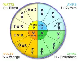
The relationship between voltage, current, and power is described by Watts' Law, which helps engineers determine electrical demand and evaluate system capacity. However, power measurements must also be interpreted alongside power factor and load type to fully understand performance.
Impedance in AC Systems
In alternating current systems, resistance alone does not determine current flow. Inductance and capacitance introduce additional opposition known as impedance.
Impedance combines resistive and reactive effects and influences how current and voltage interact in AC circuits. Motors, transformers, and transmission lines all exhibit impedance characteristics that affect power flow and voltage stability.
Understanding What Is Impedance is therefore essential when analyzing AC circuit performance, fault currents, and system behavior under load.
Capacitance and Inductance
Some electrical units appear less frequently in everyday measurements but become critical in specialized situations.
Capacitance describes the ability of a component to store energy in an electric field, while inductance describes energy stored in a magnetic field created by current flow. These characteristics influence switching behavior, transient response, and harmonic conditions in power systems.
Concepts such as Capacitance and Inductance become particularly important when analyzing power quality, filtering circuits, or systems with large motor and transformer loads.
Why Electrical Units Matter in Troubleshooting
The real purpose of electrical units becomes clear during troubleshooting. Instruments such as multimeters, clamp meters, and power analyzers provide numerical readings, but the unit attached to that number determines what the reading actually indicates.
A voltage measurement may suggest supply stability while current readings reveal overload conditions. A resistance value may identify a poor connection. Power measurements may indicate whether equipment is operating within its rated capacity.
When electrical units are interpreted correctly, they guide technicians toward accurate diagnoses and safe operating decisions. When they are misunderstood, even accurate measurements can lead to incorrect conclusions and equipment damage.
Electrical units, therefore, form the foundation of measurement, equipment design, and safe system operation. They provide the framework professionals use to interpret readings, analyze system behavior, and maintain reliable power infrastructure.