Ampere’s Law describes the relationship between magnetic fields and electric currents, a fundamental concept in electromagnetism. It explains how current produces a magnetic force, guiding the design of circuits, solenoids, coils, and transformers in electrical engineering.
What is Ampere’s Law?
Ampere's Law is a fundamental principle in electromagnetism that describes the relationship between electric current and the resulting magnetic field.
✅ It states that the magnetic field around a closed path is proportional to the electric current passing through it.
✅ It is a fundamental principle of electromagnetism, linking current and magnetic flux.
✅ Used in analyzing coils, solenoids, transformers, and magnetic circuits.
Named after the French physicist André-Marie Ampère, this powerful principle helps us understand the behaviour of magnetic fields generated by electric currents. It is crucial to develop the numerous technologies we use on a daily basis. Understanding Ampere's Law is easier when explored alongside related concepts in basic electricity, which provide the foundation for electrical theory.
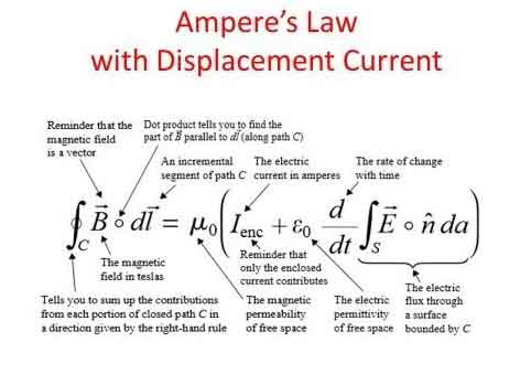
The principle states that the line integral of a magnetic field (B) around a closed loop is equal to the product of the permeability of free space (μ₀) and the net electric current (I) passing through the loop. This can be mathematically represented as:
∮ B⋅dl = μ₀I
Ampere’s Law at a Glance
| Aspect |
Explanation |
Example / Application |
| Definition |
Magnetic field around a closed loop is proportional to the net electric current passing through it. |
Helps calculate fields in wires, coils, solenoids. |
| Formula |
∮ B · dl = μ₀I (line integral of magnetic field equals permeability × current). |
Used in physics and engineering calculations. |
| Relation to Biot-Savart Law |
Both describe magnetic fields from current. Biot-Savart handles complex geometries; Ampere’s Law suits symmetrical setups. |
Magnetic field around a straight wire vs. irregular current paths. |
| Relation to Faraday’s Law |
Ampere’s Law: current → magnetic field. Faraday’s Law: changing magnetic field → induced EMF. |
Motors, generators, induction coils. |
| Role in Maxwell’s Equations |
One of the four fundamental equations of electromagnetism. |
Describes interaction of electric and magnetic fields. |
| Key Devices |
Guides design of solenoids, transformers, inductors, motors, and generators. |
Power systems, telecommunications, energy conversion. |
| Real-World Impact |
Essential to modern technology relying on electromagnetism. |
Smartphones, computers, power grids, antennas. |
Ampere’s Law and Magnetism
The principle can be applied to determine the magnetic field around current-carrying wires and other conductive materials, as well as within various electrical systems. It is an essential part of Maxwell's equations, a set of four equations that serve as the foundation of classical electromagnetism. These equations relate electric and magnetic fields to their sources (electric charges and currents) and describe how they propagate through space. The connection between electricity and magnetism is central to electromagnetism, where Ampere’s Law works hand-in-hand with Faraday’s Law to explain induction.
It calculates magnetic fields through the Biot-Savart Law, a mathematical expression that relates the magnetic field produced by a steady electric current to the current's geometry. Both principles have specific applications, with the Biot-Savart Law being more suitable for cases with intricate current configurations. At the same time, it is typically employed when dealing with symmetrical setups.
Ampere’s Law has numerous real-life applications, especially in developing and understanding devices and systems that involve electromagnetism. For example, it is used in the design of transformers, inductors, and solenoids, as well as in various applications such as telecommunications systems, motors, and generators. By applying it, engineers can predict and control the magnetic fields generated in these devices, ensuring they function optimally and efficiently.
Gauss’ Law and Electric Fields Around a Circle of Radius
When studying electromagnetism, a common problem is analyzing the behavior of electric fields around a symmetric object, such as a circle of radius r or a sphere. Gauss’ Law is especially powerful in such cases, because it states that the electric flux through a closed surface is proportional to the net charge enclosed. This means the distribution of field lines can be calculated without solving complex integrals directly.
For a uniformly charged circle of radius r, the electric field at a point along the axis can be derived by considering the superposition of contributions from each charge element. The result reveals that the electric field depends on both the radius of the circle and the distance from the observation point. This demonstrates how Gauss’ Law simplifies problems with high symmetry.
Mathematically, the relationship is expressed as:
∮ E · dA = Q / ε₀
Here, E represents the vector field of the electric field, dA is the infinitesimal area vector on the closed surface, Q is the enclosed charge, and ε₀ is the permittivity of free space. By applying this principle, one can determine that electric fields radiate symmetrically outward from charges, with strength diminishing with distance according to the geometry of the surface considered.
The application of Gauss’ Law in analyzing a circle of radius r is connected to Ampere’s Law, as both emphasize symmetry and integration around closed paths. Where Ampere’s Law links magnetic fields to current, Gauss’ Law links electric fields to charge, and together they form part of Maxwell’s equations, the foundation of electromagnetism.
Relationship between Ampere's Law and Faraday's Law
The relationship between Ampere's Law and Faraday's Law of electromagnetic induction is apparent in the phenomenon of electromagnetic induction itself. When a changing magnetic field induces an electric current in a conductive material, the resulting magnetic field generated by this electric current, in turn, affects the overall magnetic field. It helps us understand how these interacting magnetic fields behave and influence each other.
Ampere's Law and its applications in various devices and systems enable numerous technological advancements. For instance, when designing motors and generators, engineers can utilize the principle to optimize the magnetic field within the device, resulting in higher efficiency and improved performance. Ampere’s Law is also linked to the behavior of capacitance and inductance, both of which are essential in circuits and energy storage systems.
In the telecommunications realm, it helps explain the propagation of electromagnetic waves in cables and antennas. It enables engineers to design systems that minimize signal loss and maximize data transfer rates, ensuring that our smartphones, computers, and other devices remain connected and up-to-date.
By understanding the magnetic field lines and the interaction between electric current and magnetic fields, Ampere's Law opens doors to scientific discovery and innovation in numerous fields. From determining the magnetic field at a distance to the thumb rule and hand rule applications, this fundamental principle plays a crucial role in shaping the world of electromagnetism and the technology that surrounds us.
Electromagnetism
It is a cornerstone of electromagnetism that helps us understand the relationship between electric current and how it creates a magnetic field. It is a vital component of Maxwell's equations and intricately connected to other principles, such as Faraday's Law and Biot-Savart's Law. Ampere's Law has numerous applications in real-life scenarios and is essential for the functioning of many devices and systems that rely on electromagnetism. Its significance in the development of technology cannot be overstated, as it continues to drive scientific discovery and innovation. For students exploring fundamentals, the history of concepts like what is electricity and its evolution in electricity history provides valuable context to Ampere’s discoveries.
How does Ampere’s Law relate to Faraday's Law and Biot-Savart Law?
They are all essential principles in electromagnetism that describe various aspects of the interaction between electric currents and magnetic fields. Although each addresses different aspects, these are interrelated, forming a more comprehensive understanding of electromagnetism.
It describes the relationship between an electric current and its generated magnetic field. Mathematically, it states that the line integral of the magnetic field (B) around a closed loop is proportional to the net electric current (I) passing through the loop:
∮ B⋅dl = μ₀I
Ampere’s Law is useful for calculating magnetic fields in highly symmetrical situations, such as around straight wires, loops, or solenoids.
Faraday's Law: Faraday's Law of Electromagnetic Induction describes how a changing magnetic field induces an electromotive force (EMF) in a conductor. Mathematically, it states that the induced EMF is proportional to the rate of change of the magnetic flux (ΦB) through a closed loop formed by the conductor:
EMF = -dΦB/dt
Faraday's Law is fundamental to understanding the operation of devices such as generators, transformers, and induction motors, which rely on converting mechanical and electrical energy.
The Biot-Savart Law calculates the magnetic field at any point in space due to a specific current distribution. Mathematically, it can be expressed as:
dB = (μ₀ / 4π) * (Idl × r̂) / r²
The Biot-Savart Law is particularly useful for calculating magnetic fields in complex current configurations without symmetry.
Ampere's Law and Biot-Savart Law
Ampere's Law and Biot-Savart Law: Both deal with the magnetic field generated by an electric current. While the first is useful for calculating magnetic fields in symmetric situations, the Biot-Savart Law applies to a wider range of configurations, including those with intricate geometries. It can be derived from the Biot-Savart Law for specific symmetric situations.
Ampere's Law and Faraday's Law
Ampere's Law and Faraday's Law: These laws are related through Maxwell's equations, which connect electric and magnetic fields. While the first deals with the magnetic field generated by a steady electric current, Faraday's Law deals with the induced EMF resulting from a changing magnetic field. Both laws contribute to our understanding of electromagnetic phenomena and play a role in operating devices that rely on electromagnetism.
The Biot-Savart Law enables us to determine the magnetic field generated by a specific current distribution. Faraday's Law describes how a changing magnetic field can induce an EMF. In cases where the magnetic field changes due to a varying current, the Biot-Savart Law can be used to calculate the magnetic field, and then Faraday's Law can be applied to determine the induced EMF.
All three are interconnected principles in electromagnetism, each addressing a specific aspect of the interaction between the electric current and the electric field. Together, these form a more comprehensive understanding of electromagnetic phenomena and provide a basis for analyzing and designing various devices and systems that rely on electromagnetism.
Related Articles


_1497153600.webp)


