Biot Savart Law Explained

By R.W. Hurst, Editor

biot savart law

The Biot Savart Law describes how electric current generates magnetic fields, showing the relationship between current, distance, and field intensity. It is a key principle in physics, electromagnetism, and electrical engineering used to calculate magnetic effects in circuits.


What is Biot Savart Law?

The Biot Savart Law is a fundamental principle in electromagnetism that quantifies the magnetic field generated by an electric current.

✅ Relates magnetic field strength to current magnitude and distance.

✅ Provides a mathematical basis for calculating magnetic fields in circuits.

✅ Essential for understanding electromagnetism, physics, and engineering design.


Biot Savart Law and the study of electromagnetism have always been a fascinating field of science that deals with the interaction between electric and magnetic fields. One of the cornerstones in this domain is this law, named after the French scientists Jean-Baptiste Biot and Félix Savart. This law plays a vital role in understanding the behaviour of magnetic fields produced by electrical currents. The relationship between electricity and magnetism is at the heart of the Biot Savart Law, showing how moving charges generate magnetic effects.

Delving deeper into this fascinating concept, Biot Savart Law describes the magnetic field generated by a tiny current flowing through a conductor. The law states that the magnetic field at a point is directly proportional to the current and inversely proportional to the square of the distance between the point and the current-carrying conductor. Furthermore, the magnetic field's direction is perpendicular to the plane formed by the unit vector and the straight wire carrying the current. When studying current flow, it helps to compare this law with Ampere’s Law, which is often applied to symmetrical conductors and steady-state conditions.


Biot Savart Law Explained

It is a fundamental principle in electromagnetism that describes the magnetic field produced by a steady electric current. It is named after French physicists Jean-Baptiste Biot and Félix Savart, who formulated the law in 1820. It provides a means to calculate the magnetic field at any point in space due to a specific current distribution.

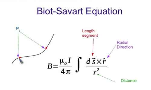
In mathematical terms, the Biot Savart Law can be expressed as:

dB = (μ₀ / 4π) * (Idl × r̂) / r²

Here,

  • dB represents the tiny magnetic field vector produced by an infinitesimal current element (Idl),

  • μ₀ is the permeability of free space (a constant with a value of 4π × 10^(-7) Tm/A),

  • I is the current flowing through the current element,

  • dl is the infinitesimal length vector of the current element,

  • r is the distance between the current element and the point in space where the magnetic field is being calculated,

  • r̂ is the unit vector pointing from the current element to the point of interest.

The Biot Savart Law states that the magnetic field produced by a small segment of a current-carrying conductor is proportional to the current, inversely proportional to the square of the distance from the point of interest, and depends on the angle between the current segment and the line connecting the segment to the point of interest.

To find the total magnetic field at a point in space due to an entire current distribution, you need to integrate the magnetic field contributions from each infinitesimal current element over the entire current-carrying conductor:

B = ∫dB

The Biot Savart Law is particularly useful for calculating the magnetic field in cases with complex current configurations or where symmetry is not apparent. In addition, it is often applied in situations where Ampere's Law would be difficult or impossible to use. Common applications include calculating magnetic fields due to straight wires, loops, and solenoids. A foundation in basic electricity concepts makes it easier to understand how current elements combine to produce magnetic fields.


Maxwell's Equations

One might wonder about the relationship between the Biot Savart Law and Maxwell's Equations, a set of fundamental equations that govern the behaviour of electric and magnetic fields. It can be derived from Maxwell's Equations, specifically Ampere's Law, which establishes a connection between an electric current and the magnetic field it generates.

While the Biot Savart Law and Ampere's Law address magnetic fields, their focus and applicability differ. For example, the Biot Savart Law is more useful for calculating magnetic fields due to current loops or irregular current-carrying conductors. In contrast, Ampere's Law best suits symmetrical geometries and steady-state currents.

The practical applications of the Biot Savart Law are abundant, ranging from designing and analyzing electromagnets and generators to determining the magnetic moment of a current loop, an essential parameter in magnetostatics. The law has also significantly advanced technologies such as magnetic resonance imaging (MRI), particle accelerators, and magnetic storage devices.

The versatility of the Biot Savart Law is exemplified by its ability to calculate magnetic fields of various geometries. From a straight wire or a solenoid to more complex configurations, such as toroidal or saddle-shaped coils, this law is a reliable tool for understanding the behaviour of magnetic fields in various scenarios.

Delving into the connections between different laws, the relationship between the Biot Savart Law and Faraday's Law is quite intriguing. While the Biot Savart Law is concerned with the magnetic field generated by a current, Faraday's Law deals with the electromotive force (EMF) induced in a conductor due to a changing magnetic field. Together, these laws form the basis of electromagnetic induction, which underpins the functioning of electric generators, transformers, and inductors.

The study of electromagnetism would only be complete by touching upon the concept of electric fields. Like magnetic fields, electric fields are fundamental aspects of electromagnetism, originating from electric charges. Coulomb's Law governs the interaction between electric charges, drawing parallels with the Biot Savart Law, which deals with magnetic fields generated by electric currents.

In the realm of vector calculus, the Biot Savart Law uses the cross product and the dot product to define the magnitude and direction of the magnetic field. These mathematical tools enable scientists and engineers to model and analyze the behaviour of magnetic fields in various applications.

One of the key parameters in the Biot Savart Law is the permeability of free space, denoted by the symbol μ₀. This constant defines the ease with which a magnetic field can permeate a vacuum and is crucial in determining the strength and range of the magnetic field generated by a current.

It is an essential concept in the study of electromagnetism. It provides a foundation for understanding magnetic fields generated by electric currents and connects with other fundamental laws, such as Ampere's Law, Faraday's Law, and Coulomb's Law. Moreover, the diverse applications of the Biot Savart Law, ranging from designing electromagnets to analyzing complex magnetic field geometries, showcase its versatility and importance.

As we continue to explore the world of electromagnetism, the Biot Savart Law will remain a crucial tool in our arsenal. Through rigorous research and innovative technologies, scientists and engineers will continue to unlock the mysteries of electric and magnetic fields, ultimately leading to groundbreaking discoveries and advancements that have the potential to transform our world.

From powering our homes with electricity to enabling cutting-edge technologies like MRI machines and particle accelerators, it plays a central role in shaping the science and engineering landscape. As we progress into the future, the Biot Savart law will undoubtedly continue to serve as a beacon of knowledge and understanding in the ever-evolving realm of electromagnetism. For a broader perspective on how energy sources shape our electrical systems, exploring alternative electricity provides useful context.


Related Articles


Related News

Electricity and Magnetism - Power Explained

Electricity and magnetism are interconnected forces forming electromagnetism, which explains electric currents, magnetic fields, and their interactions. These principles power motors, generators, transformers, and more in modern electrical and magnetic systems.


What is: "Electricity and Magnetism"

Electricity and magnetism are fundamental forces in physics that form the basis of electromagnetism.

✅ Describe how electric charges and magnetic fields interact in nature and technology

✅ Underlie the function of motors, transformers, and generators

✅ Explain current flow, induction, and electromagnetic waves

Electricity - What is it?

Electricity is a form of energy that is transmitted through copper conductor wire to power the operation of electrical machines and devices, including industrial, commercial, institutional, and residential lighting, electric motors, electrical transformers, communications networks, home appliances, and electronics.

When charged particles flow through the conductor, we call it "current electricity". This is because when the charged particles flow through wires, electricity also flows. We know that current means the flow of anything in a particular direction. For example, the flow of water. Similarly, the flow of electricity in a specific direction is referred to as an electric current. The interplay of charge, field, and force is explored in what is electric load, covering how power is delivered in electromagnetic systems.

When an electric current flows, it produces a magnetic field, a concept closely tied to Faraday's Law of Induction, which underpins much of modern electrical engineering.


Magnetism  - What is it?

Magnetism is a type of attractive or repulsive force that acts up to certain distance at the speed of light. The distance up to which this attractive or repulsive force acts is called a "magnetic field". Magnetism is caused by the moving electric charges (especially electrons). When two magnetic materials are placed close to each other, they experience an attractive or repulsive force. To understand magnetic field strength and units, our magnetic induction basics in induction page discusses flux and Teslas.


What is the relationship between electricity and magnetism?

In the early days, scientists believed that there were two uniquely separate forces. However, James Clerk Maxwell proved that these two separate forces were actually interrelated.

In 1820, Hans Christian Ørsted observed a surprising phenomenon: when he switched on the battery from which the electric current was flowing, the compass needle moved away from the north pole. After this experiment, he concluded that the electric current flowing through the wire produces a magnetic field.

Electricity and magnetism are closely related to each other. The electric current flowing through the wire produces a circular magnetic field outside the wire. The direction (clockwise or counterclockwise) of this magnetic field depends on the direction of the electric current.

Similarly, a changing magnetic field generates an electric current in a wire or conductor. The relationship between them is called electromagnetism.

Electricity and magnetism are interesting aspects of electrical sciences. We are familiar with the phenomenon of static cling in our everyday lives - when two objects, such as a piece of Saran wrap and a wool sweater, are rubbed together, they cling.

One feature of this that we don't encounter too often is static "repulsion" - if each piece of Saran wrap is rubbed on the wool sweater, then the pieces of Saran wrap will repel when brought near each other. These phenomena are interpreted in terms of the objects acquiring an electric charge, which has the following features:

  • There are two types of charge, which by convention are labelled positive and negative.

  • Like charges repel, and unlike charges attract.

  • All objects may have a charge equal to an integral number of a basic unit of charge.

  • Charge is never created or destroyed.

To explore how electric and magnetic forces interact at a distance, see what is static electricityis, which includes examples like static cling and repulsion.


Electric Fields

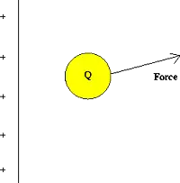
A convenient concept for describing these electric current and magnetic current forces is that of electric field currents. Imagine that we have a fixed distribution of charges, such as on the plate below, and bring a test charge Q into the vicinity of this distribution.


img134 
 

Fig. 1 Test charge in the presence of a fixed charge distribution

This charge will experience a force due to the presence of the other charges. One defines the electric field of the charge distribution as:


img135

The electric field is a property of this fixed charge distribution; the force on a different charge Q' at the same point would be given by the product of the charge Q' and the same electric field. Note that the electric field at Q is always in the same direction as the electric force.

Because the force on a charge depends on the magnitude of the charges involved and the distances separating them, the electric field varies from point to point, both in magnitude and direction.

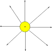
By convention, the direction of the electric field at a point is the direction of the force on a positive test charge placed at that point. An example of the electric field due to a positive point charge is given below. 


img136

Fig. 2: Electric field lines of a positive charge


Power and Magnetic Fields

A phenomenon apparently unrelated to power is electromagnetic fields. We are familiar with these forces through the interaction of compasses with the Earth's magnetic field, or the use of fridge magnets or magnets on children's toys. Magnetic forces are explained in terms very similar to those used for electric forces:

  • There are two types of magnetic poles, conventionally called North and South
  • Like poles repel, and opposite poles attract

However, this attraction differs from electric power in one important aspect:

  • Unlike electric charges, magnetic poles always occur in North-South pairs; there are no magnetic monopoles.

Later on we will see at the atomic level why this is so.

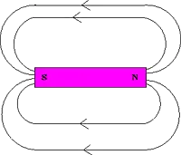
As in the case of electric charges, it is convenient to introduce the concept of a magnetic field in describing the action of magnetic forces. Magnetic field lines for a bar magnet are pictured below.

img137
 

Fig. 3: Magnetic field lines of a bar magnet

One can interpret these lines as indicating the direction that a compass needle will point if placed at that position.

The strength of magnetic fields is measured in units of Teslas (T). One tesla is actually a relatively strong field - the earth's magnetic field is of the order of 0.0001 T.


Magnetic Forces On Moving Charges

One basic feature is that, in the vicinity of a magnetic field, a moving charge will experience a force. Interestingly, the force on the charged particle is always perpendicular to the direction it is moving. Thus, magnetic forces cause charged particles to change their direction of motion, but they do not change the speed of the particle.

This property is utilized in high-energy particle accelerators to focus beams of particles, which ultimately collide with targets to produce new particles, including gamma rays and radio waves.

Another way to understand these forces of electricity and magnetism is to realize that if the force is perpendicular to the motion, then no work is done. Hence, these forces do no work on charged particles and cannot increase their kinetic energy.

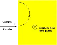
If a charged particle moves through a constant magnetic field, its speed stays the same, but its direction is constantly changing. A device that utilizes this property is the mass spectrometer, which is used to identify elements. A basic mass spectrometer is pictured below.


img145
 

Figure 4: Mass spectrometer

In this device, a beam of charged particles (ions) enters a region of a magnetic field, where they experience a force and are bent in a circular path. The amount of bending depends on the mass (and charge) of the particle, and by measuring this amount one can infer the type of particle that is present by comparing it to the bending of known elements.


Magnet Power From Electric Power

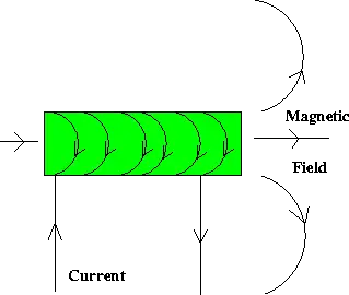
A connection was discovered (accidentally) by Orsted over 100 years ago, when he noticed that a compass needle is deflected when brought into the vicinity of a current-carrying wire. Thus, currents induce magnetic fields in their vicinity. An electromagnet is simply a coil of wires which, when a current is passed through, generates a magnetic field, as below.


img149
 

Figure 5: Electromagnet

Another example is in an atom, where an electron is a charge that moves around the nucleus. In effect, it forms a current loop, and hence, a magnetic field may be associated with an individual atom. It is this basic property which is believed to be the origin of the magnetic properties of various types of materials found in nature.

Maxwell's equations (also known as Maxwell's theory) are a set of coupled partial differential equations that, together with the Lorentz force law, form the foundation of classical electromagnetism, which deals with electromagnetic radiation, electromagnetic waves, and electromagnetic force.  For a deeper understanding of the magnetic effects of electrical current, our article on electromagnetic induction explains how magnetic fields can generate electricity in conductors.


Related Articles


View more

Electricity Grid - T&D

Electricity grid infrastructure delivers power through transmission lines, substations, and smart grid controls, balancing voltage and frequency, integrating renewable energy, enabling demand response, improving reliability, and supporting utilities with real-time monitoring and load management.


What Is the Electricity Grid?

A network of transmission, distribution, and control systems that delivers reliable electrical power to consumers.

✅ Transmits high-voltage power from plants to local networks

✅ Steps down voltage at substations for safe distribution

✅ Integrates renewables with smart grid and demand response


The electricity grid is a complex and essential component of modern society. It provides the power necessary to operate homes, businesses, and industries, and it is constantly evolving to meet the demands of a changing world. From power generation to distribution, transmission lines to load balancing and renewable energy integration, every component is critical in ensuring we can access reliable and affordable energy whenever needed. For a broader primer, resources such as electric power systems outline how these elements interconnect in practice.

At its core, the grid is a system that connects power generation facilities to consumers through transmission lines and distribution systems. It is designed to move electricity from where it is generated to where it is needed, whether in a residential home or a large industrial facility. The term "grid" refers to the interconnectedness of these systems, which allows power to flow from one location to another as needed. The federal energy regulatory commission ferc regulates the grid.

In North America, the transmission and distribution (T&D) grid is managed by federal, state, provincial, and territorial agencies. The grid is divided into various regions, each with its grid operator responsible for ensuring reliable and efficient operation within their respective jurisdiction. For instance, Canada's power delivery network is divided into four main regions: Western Canada, Ontario, Quebec, and the Atlantic region. Similarly, the United States' electricity grid is divided into three major interconnected systems: the Eastern Interconnection, Western Interconnection, and the Electric Reliability Council of Texas (ERCOT) system. Each region's grid operator works closely with neighbouring grid operators to ensure a seamless flow of electrical power across the interconnected grid, even during periods of high demand or unexpected outages.

The power delivery network can be broken down into three main components: power generation, transmission, and distribution. Power generation facilities can take many forms, including coal-fired, natural gas, nuclear, and renewable energy sources such as wind and solar. These facilities generate electrical power transmitted over high-voltage transmission lines to substations, where the voltage is lowered for distribution to homes and businesses through a network of distribution lines. For those new to supply technologies, overviews of how electricity is generated cover conventional and renewable pathways.

Transmission lines are a critical component of the T&D system, which deliver and produce electricity at higher voltages. T&D provides the means to move large amounts of electrical power over long distances. These lines are typically made of high-strength steel or aluminum and span hundreds of miles. They are also designed to be highly resilient to extreme weather events such as hurricanes, tornadoes, and ice storms. Understanding ratings, capacity, and losses draws on electricity power fundamentals that inform planning and operations.

The distribution system is the final component of the power grid, responsible for delivering electrical power directly to homes and businesses. This system includes transformers, power lines, and meters, which work together to regulate power flow to individual consumers. The distribution system also includes local power generation facilities, such as rooftop solar panels and small-scale wind turbines, which can supplement the power provided by the grid. To see how fuel mixes influence local grids, summaries of sources of electricity highlight regional differences.

As the world increasingly relies on electrical power, there is a growing need to modernize and upgrade the power delivery network to meet the demands of the 21st century. One approach to this is the development of a smart grid, which uses advanced sensors, communication networks, and analytics to optimize the flow of power and improve reliability. Another approach is the integration of renewable energy sources such as wind and solar into the grid, which can reduce greenhouse gas emissions and improve grid resilience. Advanced planning and forecasting increasingly leverage power system analysis to evaluate contingencies and optimize investments.

Load balancing is another critical function, ensuring that real-time power generation and consumption are matched. This is accomplished through a combination of forecasting, automated control systems, and energy storage facilities such as batteries and pumped hydroelectric storage. In flexible markets, insights into electricity generation help operators schedule resources effectively.

Reliability and resilience are also crucial factors in its overall performance. The grid must be designed to withstand extreme weather events and other disruptions, such as cyberattacks or equipment failures. This requires a combination of robust engineering and effective emergency response planning.


What is an electricity grid, and how does it work?

A T&D system is a complex network of power generation facilities, transmission lines, and distribution systems that work together to ensure reliable and affordable energy is available to consumers. At its core, the grid is a system that connects power generation facilities to consumers through transmission lines and distribution systems. It is designed to move electrical power from where it is generated to where it is needed, whether in a residential home or a large industrial facility. The grid uses high-voltage transmission lines to move electrical power over long distances, then lowers the voltage through transformers for distribution to homes and businesses. For foundational clarity, a concise explainer on what electricity is helps connect basic concepts to grid operations.


What is the difference between the transmission and distribution systems?

The transmission system is responsible for moving large amounts of electrical power over long distances at high voltages. This is accomplished through a network of high-voltage transmission lines and substations spanning hundreds of miles. The distribution system delivers electrical power directly to homes and businesses at lower voltages. This system includes transformers, power lines, and meters, which work together to regulate the flow of electricity to individual consumers.


How is renewable energy integrated?

Renewable energy sources such as wind and solar are integrated into the T&D system through a process called interconnection. This involves connecting the renewable energy source to the grid through a substation and transformer, ensuring that the energy generated can be transmitted to consumers. Renewable energy sources can also be connected to the grid through distributed generation, where energy is generated on-site at the point of consumption, such as through rooftop solar panels.


What are the challenges associated with maintaining the reliability and resilience of the T&D system?

Maintaining reliability and resilience is a complex task requiring robust engineering and effective emergency response planning. Some of the challenges associated with this include extreme weather events, cyberattacks, equipment failures, and natural disasters. In addition, as the grid becomes more reliant on renewable energy sources, new challenges may arise related to load balancing and energy storage.


What is a smart grid, and how does it differ from a traditional T&D system?

A smart grid is a modernized version of the traditional T&D system that uses advanced sensors, communication networks, and analytics to optimize the flow of electrical power and improve reliability. Unlike a traditional T&D system, designed to move electrical power from power plants to consumers, a smart grid enables two-way communication between consumers and the grid. This allows for greater control and flexibility in managing energy usage and improved efficiency and reliability.


How can energy storage be used to support the T&D system?

Energy storage can be used to support the T&D system in several ways. One essential function is to provide backup power in the event of a blackout or other disruption to the grid. Energy storage can also help balance the load on the grid, ensuring that power generation and consumption are matched in real-time. In addition, energy storage can help integrate renewable energy sources into the grid by storing excess energy for use during times of low generation.


What is grid modernization, and why is it important for the future of the T&D system?

Grid modernization refers to upgrading and improving the T&D system to meet the demands of a changing world. This may involve the development of a smart grid, the integration of renewable energy sources, and the deployment of advanced sensors and control systems. Grid modernization is important for the future of the T&D system because it will enable greater efficiency, reliability, and sustainability while ensuring that the grid is resilient to emerging threats and challenges.


Related Articles

View more

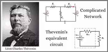
Thevenin's Theorem

Thevenin’s Theorem simplifies complex linear circuits into a single voltage source and series resistance, making circuit analysis easier for engineers. It helps calculate current, load behavior, and equivalent resistance in practical electrical systems.


What is Thevenin’s Theorem?

Thevenin’s Theorem is a method in circuit analysis that reduces any linear electrical network to an equivalent circuit with a voltage source (Vth) in series with a resistance (Rth).

✅ Simplifies circuit analysis for engineers and students

✅ Calculates load current and voltage with accuracy

✅ Models equivalent resistance for real-world applications

Thevenin’s Theorem allows any linear, two-terminal circuit to be represented by a single voltage source in series with a resistance.

  • Reduces complex circuits to a simple equivalent consisting of a voltage source and a resistor

  • Makes analyzing load response and network behavior straightforward, saving time and effort

  • Widely used for calculating current, voltage, or power across loads in electrical networks

To fully grasp why Thevenin’s Theorem matters, it helps to revisit the principles of basic electricity, where voltage, current, and resistance form the foundation of all circuit analysis.


Understanding Thevenin’s Theorem

Thevenin’s Theorem is a cornerstone of basic electrical engineering and circuit analysis. First introduced by French engineer Léon Charles Thévenin in the late 19th century, the theorem allows engineers and students alike to simplify a complex electrical network to a single voltage source (known as the Thevenin voltage, Vth) in series with a single resistor (known as the Thevenin resistance, Rth). This is particularly useful when analyzing how a circuit will behave when connected to different loads. Concepts such as Ohm’s Law and electrical resistance work in conjunction with Thevenin’s method, ensuring accurate load and network calculations.

Thevenin’s Theorem states that any linear electrical network can be simplified to an equivalent circuit consisting of a single voltage source in series with a resistance. By removing the load resistance, engineers can calculate the equivalent circuit voltage at the terminals, which represents how the circuit will behave when reconnected. This approach replaces multiple components and ideal voltage sources with one simplified model, making circuit analysis more efficient while preserving accuracy in predicting load behavior.


How Thevenin’s Theorem Works

According to Thevenin’s Theorem, no matter how complicated a linear circuit may be, with multiple sources and resistors, it can be replaced by an equivalent Thevenin circuit. This greatly simplifies the process when you’re only interested in the voltage, current, or power delivered to a specific part of the circuit. The steps typically followed when using Thevenin’s Theorem are:

  1. Identify the portion of the circuit for which you want to find the Thevenin equivalent (usually across two terminals where a load is or will be connected).

  2. Remove the load resistor and determine the open-circuit voltage across the terminals. This voltage is the Thevenin voltage (Vth).

  3. Calculate the Thevenin resistance (Rth) by deactivating all independent voltage sources (replace them with short circuits) and current sources (replace them with open circuits), then determining the resistance viewed from the terminals.

  4. Redraw the circuit as a single voltage source Vth in series with resistance Rth, with the load resistor reconnected.


Why Use Thevenin’s Theorem?

There are several reasons why Thevenin’s Theorem is so widely used in both academic and practical electrical engineering:

  • Simplification – Instead of solving a complex network repeatedly each time the load changes, engineers can just reconnect different loads to the Thevenin equivalent, saving time and reducing the potential for error.

  • Insight – By reducing a circuit to its essential characteristics, it’s easier to understand how changes will affect load voltage, current, or power.

  • Foundation for Further Analysis – Thevenin’s Theorem forms the basis for other network analysis techniques, such as Norton's Theorem, and is fundamental to understanding more advanced topics like maximum power transfer.


Example Application

Imagine a scenario where you need to analyze a circuit with multiple resistors and voltage sources connected in series, with a load resistor at the end. Without Thevenin’s Theorem, calculating the voltage across or current through the load each time you change its resistance would require solving complicated sets of equations. Thevenin’s Theorem allows you to do all the hard work once, finding Vth and Rth, and then quickly see how the load responds to different values.

Illustrative Case: A power supply circuit needs to be tested for its response to varying loads. Instead of recalculating the entire network for each load, the Thevenin equivalent makes these calculations swift and efficient. A deeper look at capacitance and inductance shows how energy storage elements influence circuit behavior when simplified through equivalent models.


Limitations and Conditions

While powerful, Thevenin’s Theorem has limitations:

  • It only applies to linear circuits, those with resistors, sources, and linear dependent sources.

  • It cannot directly simplify circuits containing nonlinear elements such as diodes or transistors in their nonlinear regions.

  • The theorem is most useful for “two-terminal” or “port” analysis; it doesn’t help as much with multiple output terminals simultaneously, though extensions exist.


Connections to Broader Electrical Concepts

Thevenin’s Theorem is closely related to other concepts, such as Norton’s Theorem, which prescribes an equivalent current source and parallel resistance. Both theorems are widely applied in real-world scenarios, including power distribution, signal analysis, and the design of electronic circuits. For example, it's relevant when considering how hydro rates impact load distribution in utility networks.

Thevenin’s Theorem is more than just a trick for simplifying homework—it is a core analytical tool that forms the backbone of practical circuit analysis. Whether you are a student learning circuit theory or an engineer designing power systems, understanding and applying Thevenin’s Theorem is essential.  Understanding current flow and the role of a conductor of electricity provides practical insight into why reducing networks to simple equivalents makes engineering analysis more efficient.


Related Articles


View more

3 PHASE ELECTRICITY

3 Phase Electricity supplies AC three-phase power via 120° phase-shifted sinusoidal waveforms, enabling balanced loads, higher power factor, efficient distribution, and smooth torque for industrial motors across commercial facilities and the electrical grid.


What Is 3 Phase Electricity?

An AC system with three sinusoidal phases delivering balanced, efficient power for distribution and industrial motors.

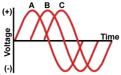
✅ Three 120° phase-shifted AC waveforms share balanced loads.

✅ Lower conductor size and losses than single-phase systems.

✅ Powers large motors with smoother torque and better efficiency.


3 phase electricity is referred to alternating current. It is best described as the timing of the electron movements. It is the most common delivery method worldwide because it is a cheaper and easier way to transmit power from one place to another. While this method of electrical transmission is popular in industrial, commercial and institutional power systems, most homes only use single-phase power. For a concise overview, see the three-phase electricity guide for context.


What does it mean?

If wires are in "phase", it means that timing of the electron movement, back and forth, is the same. The electrons are "in step" or "in time".

For newcomers, the basic electricity tutorial explains charge, current, and phase in simple terms.

To transmit and distribute alternating current, it is more efficient to use 3 circuits that are out of sequence. This idea was discovered by Nikola Tesla (1856 -1943). Much of its efficiency is because there is always voltage (electrons moving) in at least one wire.

You can review how alternating current behaves in circuits in the how electricity works resource to see why shifting phases improves continuity.

He found that it is an arrangement that fits in very nicely with generator design. The 120° phasing separation allows close to the optimum spacing and size of the copper conductors around the stator bore. The compatible generator is the cheapest form to make. Design notes for 3-phase power highlight how 120° spacing reduces copper and iron losses.

This type of power is designed especially for large electrical loads where the total electrical load is divided among the three separate phasing sequences. As a result, the wire and transformers will be less expensive than if these large loads were carried on a single system.

Generators usually have three separate windings, each producing its own separate single-phase voltage. Since these windings are staggered around the generator circumference, each of the voltages is "out of phase" with one another. That is, each of the three reaches the maximum and minimum points in the AC cycle at different times.

Definitions of "phase angle" and "phase sequence" are covered in the electricity terms glossary for reference.

Power is generated at electric utilities in this way. But, if this power is better than single phase, why not four, five or six phase? Theoretically, these would be even better, but equipment manufacturers would have to build motors to use it, and that just wouldn't be cost effective given the installed base of equipment that must continue to be powered. Utility practices for distribution are summarized in the electricity supply overview which also outlines standard voltage systems.

The word is often abbreviated using the Greek letter "phi" and is written as a zero with a slash mark through it.

The most important class of load is the electric motor. An induction motor has a simple design, inherently high starting torque, and high efficiency. Such motors are applied in industry for pumps, fans, blowers, compressors, conveyor drives, and many other kinds of motor-driven equipment. A motor will be more compact and less costly than a motor of the same voltage class and rating; and AC motors above 10 HP (7.5 kW) are uncommon. Three phase motors will also vibrate less and hence last longer than motor of the same power used under the same conditions.

Large air conditioning, etc. equipment use motors for reasons of efficiency, economy and longevity.

Resistance heating loads such as electric boilers or space heating may be connected to systems. Electric lighting may also be similarly connected. These types of loads do not require the revolving magnetic field characteristic of motors but take advantage of the higher voltage and power level usually associated with distribution. Fluorescent lighting systems also benefit from reduced flicker if adjacent fixtures are powered from different.

Large rectifier systems may have inputs; the resulting DC current is easier to filter (smooth) than the output of a rectifier. Such rectifiers may be used for battery charging, electrolysis processes such as aluminum production, or for operation of DC motors.

An interesting example of a load is the electric arc furnace used in steelmaking and in refining of ores.

In much of Europe stoves are designed to allow for a feed. Usually the individual heating units are connected between phase and neutral to allow for connection to a supply where this is all that is available.

For homeowners, the home electricity section explains single-phase panels, breakers, and typical loads.


Related Articles

View more

Electrical Units Explained

Electrical units measure various aspects of electricity, such as voltage (volts), current (amperes), resistance (ohms), and power (watts). These standard units are crucial in electrical engineering, circuit design, energy monitoring, and ensuring the safe operation of electrical systems.


What are Electrical Units?

Electrical units are standardized measures used to quantify electrical properties in circuits and systems.

✅ Measure voltage, current, resistance, power, and energy

✅ Used in electrical engineering, testing, and design

✅ Support safe and efficient electrical system operations

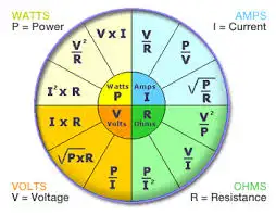
Electrical units are standardized measurements that describe various aspects of electricity, such as current, voltage, resistance, and power. These units, like amperes for current and volts for voltage, help quantify the behavior and interaction of systems. By understanding electrical units, professionals can assess performance, design circuits, and ensure safety across different applications. These electrical units play a crucial role in the functioning of everything from household appliances to industrial machinery, making them fundamental in engineering and everyday technology.

In common electricity systems, various electrical units of measure, such as magnetic field, are used to describe how electricity flows in the circuit. For example, the unit of resistance is the ohm, while the unit of time is the second. These measurements, often based on SI units, help define the phase angle, which describes the phase difference between current and voltage in AC circuits. Understanding these electrical units is critical for accurately analyzing performance in both residential and industrial applications, ensuring proper function and safety.


Ampere

The ampere is the unit of electric current in the SI, used by both scientists and technologists. Since 1948, the ampere has been defined as the constant current that, if maintained in two straight, parallel conductors of infinite length and negligible circular cross-section, and placed one meter apart in a vacuum, would produce between these conductors a force equal to 2 × 10^7 newtons per meter of length. Named for the 19th-century French physicist André-Marie Ampere, it represents a flow of one coulomb of electricity per second. A flow of one ampere is produced in a resistance of one ohm by a potential difference of one volt. The ampere is the standard unit of electric current, playing a central role in the flow of electricity through electrical circuits.


Coulomb

The coulomb is the unit of electric charge in the metre-kilogram—second-ampere system, the basis of the SI system of physical electrical units. The coulomb is defined as the quantity of electricity transported in one second by a current of one ampere. Named for the I8th—I9th-century French physicist.


Electron Volt

A unit of energy commonly used in atomic and nuclear physics, the electron volt is equal to the energy gained by an electron (a charged particle carrying one unit of electronic charge when the potential at the electron increases by one volt. The electron volt equals 1.602 x IO2 erg. The abbreviation MeV indicates 10 to the 6th (1,000,000) electron volts, and GeV, 10 to the 9th (1,000,000,000). For those managing voltage drop in long circuits, we provide a helpful voltage drop calculator and related formulas to ensure system efficiency.


Faraday

The Faraday (also known as the Faraday constant) is used in the study of electrochemical reactions and represents the amount of electric charge that liberates one gram equivalent of any ion from an electrolytic solution. It was named in honour of the 19th-century English scientist Michael Faraday and equals 6.02214179 × 10^23 coulombs, or 1.60217662 × 10^-19 electrons.


Henry

The henry is a unit of either self-inductance or mutual inductance, abbreviated h (or hy), and named for the American physicist Joseph Henry. One henry is the value of self-inductance in a closed circuit or coil in which one volt is produced by a variation of the inducing current of one ampere per second. One henry is also the value of the mutual inductance of two coils arranged such that an electromotive force of one volt is induced in one if the current in the other is changing at a rate of one ampere per second.


Ohm

The unit of resistance in the metre-kilogram-second system is the ohm, named in honour of the 19th-century German physicist Georg Simon Ohm. It is equal to the resistance of a circuit in which a potential difference of one volt produces a current of one ampere (1 ohm = 1 V/A); or, the resistance in which one watt of power is dissipated when one ampere flows through it. Ohm's law states that resistance equals the ratio of the potential difference to current, and the ohm, volt, and ampere are the respective fundamental electrical units used universally for expressing quantities. Impedance, the apparent resistance to an alternating current, and reactance, the part of impedance resulting from capacitance or inductance, are circuit characteristics that are measured in ohms. The acoustic ohm and the mechanical ohm are analogous units sometimes used in the study of acoustic and mechanical systems, respectively. Resistance, measured in ohms, determines how much a circuit resists current, as explained in our page on Ohm’s Law.


Siemens

The siemens (S) is the unit of conductance. In the case of direct current (DC), the conductance in siemens is the reciprocal of the resistance in ohms (S = amperes per volt); in the case of alternating current (AC), it is the reciprocal of the impedance in ohms. A former term for the reciprocal of the ohm is the mho (ohm spelled backward). It is disputed whether Siemens was named after the German-born engineer-inventor Sir William Siemens(1823-83) or his brother, the engineer Werner von Siemens (1816-92).


Volt

The unit of electrical potential, potential difference, and electromotive force in the metre—kilogram—second system (SI) is the volt; it is equal to the difference in potential between two points in a conductor carrying one ampere of current when the power dissipated between the points is one watt. An equivalent is the potential difference across a resistance of one ohm when one ampere of current flows through it. The volt is named in honour of the I8th—I9th-century Italian physicist Alessandro Volta. Ohm's law defines these electrical units, where resistance equals the ratio of potential to current, and the respective units of ohm, volt, and ampere are used universally for expressing electrical quantities. Energy consumption is measured in kWh, or kilowatt-hours. Explore how devices like ammeters and voltmeters are used to measure current and voltage across components. To better understand how voltage is measured and expressed in volts, see our guide on what is voltage.


Watt

The watt is the unit of power in the SI equal to one joule of work performed per second, or to 1/746 horsepower. An equivalent is the power dissipated in a conductor carrying one ampere of current between points at a one-volt potential difference. It is named in honour of James Watt, British engineer and inventor. One thousand watts equals one kilowatt. Most electrical devices are rated in watts. Learn how a watt defines power in electrical systems and its relationship to volts and amperes through Watts' Law.


Weber

The weber is the unit of magnetic flux in the SI, defined as the amount of flux that, linking a circuit of one turn (one loop of wire), produces in it an electromotive force of one volt as the flux is reduced to zero at a uniform rate in one second. It was named in honour of the 19th-century German physicist Wilhelm Eduard Weber and equals 10 to the 8th maxwells, the unit used in the centimetre—gram—second system.

Related Articles


View more

Electric Power Systems

Electric power systems manage generation, transmission, and distribution across grids and substations, using protection relays, SCADA, and control systems to ensure reliability, stability, power quality, and efficient load flow with renewable integration.


What Are Electric Power Systems?

Networks that generate, transmit, and distribute power, ensuring reliability, stability, and efficient grid operation.

✅ Includes generation, transmission, distribution, and substations.

✅ Uses protection, SCADA, and controls for reliability and safety.

✅ Integrates renewables with load flow, stability, and demand forecasting.


Electric power systems have evolved significantly in recent years, driven by the increasing demand for clean and sustainable energy sources. Advancements in renewable energy integration, smart grid technology, energy storage, and microgrids are transforming how we generate, transmit, and consume electricity. In addition, as the world continues to face the challenges of climate change and security, developing and implementing these technologies are essential for building a more sustainable and resilient future. Readers new to core concepts can review what electricity is to connect these technologies with fundamental principles.


The main components of an electric power system include generation, transmission and distribution, and load management. Generation refers to producing energy from various sources such as fossil fuels, nuclear and renewable energy. Renewable electrical energy sources, like solar, wind, and hydro, are increasingly being integrated into electric power systems to reduce dependence on fossil fuels and decrease greenhouse gas emissions. However, integrating renewable energy sources requires advanced technologies and strategies to maintain grid stability. For a concise survey of primary resources, see major sources of electricity for additional context on resource mixes. Those interested in the conversion processes can explore how electricity is generated to understand key methods and tradeoffs.

One such technology is the smart grid, an intelligent network that uses digital communication technology to monitor and control the flow of electricity. Smart grids enable better integration of renewable sources by managing their intermittent nature and ensuring grid stability. Additionally, smart grids facilitate demand response, a mechanism that encourages consumers to adjust their consumption based on real-time price signals, ultimately leading to more efficient use of resources. For system-level context on grid architecture, the overview at electricity grid basics explains how modern networks coordinate supply and demand.

Energy storage plays a crucial role, particularly in renewable integration. By storing excess energy generated during periods of low demand, energy storage systems can help balance supply and demand, improve grid stability, and reduce the need for additional generation plants. Some common energy storage technologies include batteries, pumped hydro, and flywheels. For background on production metrics that storage helps smooth, consult electricity production data to see how output varies across time.

Microgrids, small-scale systems that can operate independently or in conjunction with the main grid, contribute to more resilient systems. They often incorporate renewable sources, storage, and advanced control systems to provide a reliable electricity supply, especially during grid outages or emergencies. Microgrids can also reduce losses associated with long-distance electricity transmission and help alleviate stress on the main grid.

Grid stability remains one of the key challenges. The integration of renewable sources and the increasing demand for electricity place significant stress on the existing infrastructure. Solutions for grid stability include advanced control systems, energy storage, and distributed generation. Distributed generation refers to smaller-scale generation units, like solar panels or wind turbines, located closer to the end-users, which can help reduce the burden on the main grid. Engineers use rigorous studies such as power system analysis to evaluate contingencies and design robust operating strategies.

Demand response is managed in modern electric power systems through advanced communication and control technologies. Real-time data on consumption and generation allows utilities to adjust pricing and encourage consumers to shift their usage patterns, helping to reduce peak demand and improve overall system efficiency.

Emerging technologies in electric power systems include single-phase and three-phase power supplies designed to deliver electricity more efficiently and effectively to various types of loads. Single-phase power is typically used in residential settings, while three-phase power is more commonly used in commercial and industrial applications. Innovations in electrical engineering in the United States also drive advancements in transmission and distribution systems, focusing on reducing losses and improving reliability. A broader view of production scaling and plant types is provided in electricity generation overviews that link equipment choices with system performance.


Related Articles

View more

Sign Up for Electricity Forum’s Newsletter

Stay informed with our FREE Newsletter — get the latest news, breakthrough technologies, and expert insights, delivered straight to your inbox.

Electricity Today T&D Magazine Subscribe for FREE

Stay informed with the latest T&D policies and technologies.
  • Timely insights from industry experts
  • Practical solutions T&D engineers
  • Free access to every issue

Live Online & In-person Group Training

Advantages To Instructor-Led Training – Instructor-Led Course, Customized Training, Multiple Locations, Economical, CEU Credits, Course Discounts.

Request For Quotation

Whether you would prefer Live Online or In-Person instruction, our electrical training courses can be tailored to meet your company's specific requirements and delivered to your employees in one location or at various locations.