Arc Flash
OSHA Lockout Tagout Training - Electrical Safety Course
Download Our FREE Arc Flash Handbook
Our Electrical Safety and Arc Flash Handbook Volume 11 is the most popular handbook in our handbook series.
Our latest Arc Flash and Electrical Safety Handbook Volume 11 is a valuable source of information for electrical professionals working in Industrial, Commercial and Institutional power systems who are exposed to the risk of arc flash accidents, which can cause serious injury and death.
This 96-page FREE to download handbook examines important electrical safety issues faced by front line electrical workers.
Table of Contents
CHAPTER ONE - Arc Flash And Blast
CHAPTER TWO - Arc Flash Codes And Standards
CHAPTER THREE - Arc Flash In The Workplace
CHAPTER FOUR - Electrical Safety Procedures
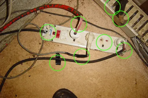
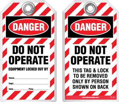
CHAPTER FIVE - Lockout Tagout
CHAPTER SIX - Arc Flash PPE
CHAPTER SEVEN - Arc Flash Training
CHAPTER EIGHT - Arc Flash Anaylsis
CHAPTER NINE - Arc Flash Consulting
Download Today!
Latest Arc Flash Articles
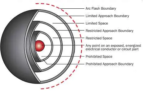
Prohibited Approach Boundary

Qualified Electrical Worker: Tasks Explained
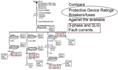
Incident Energy Explained

How are arc flash and electric shock protection boundaries determined?
CSA Z462 Tables Explained