Latest Arc Flash Articles
OSHA Electrical Safety Standards
OSHA electrical safety standards exist to protect workers from shock, fire, and high-energy electrical hazards in workplaces where electricity is present. These requirements define how employers must recognize hazards, control risk, and apply safe work practices under federal occupational safety and health law.
Electrical safety is not a single rule or checklist. It is an enforcement framework grounded in industry practices, built on hazard recognition, employee qualification, and reasonable protection. The Occupational Safety and Health Administration evaluates whether employers took appropriate steps to prevent foreseeable harm when employees work on or near electrical equipment.
OSHA electrical safety requirements do not…
View more
Sign Up for Electricity Forum’s Arc Flash Newsletter
Stay informed with our FREE Arc Flash Newsletter — get the latest news, breakthrough technologies, and expert insights, delivered straight to your inbox.
Electrical Safety Signs
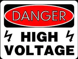
Electrical safety signs communicate hazards with standardized symbols, colors, and labels, supporting OSHA and ISO 7010 compliance, arc flash warnings, shock risk alerts, PPE requirements, lockout/tagout, and emergency shutoff identification.
Understanding Electrical Safety Signs for Compliance with NFPA 70E
Electrical safety signs are an essential tool for maintaining a safe working environment in industries where hazards are present. These warnings help identify hazards, prevent accidents, inform workers of potential risks, and ensure that proper procedures are followed. Whether cautions about high voltage, arc flash, or other dangers, these serve as a critical reminder of the steps workers need to…
View more
How long does an arc flash last?
How long does arc flash last? Typically milliseconds to a few seconds, depending on fault current, protection clearing time, incident energy, equipment, and NFPA 70E safeguards, affecting PPE selection and electrical safety risk.
How Long Does Arc Flash Last?
An arc flash typically lasts less than a second, depending on fault current and protection device speed. While the physical event is brief, the impact on personnel and equipment can be long-lasting and severe.
For a concise overview of how these events initiate and propagate, see our resource on what an arc flash is and how it relates to clearing…
View more
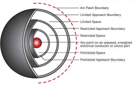
Minimum Approach Distance Chart
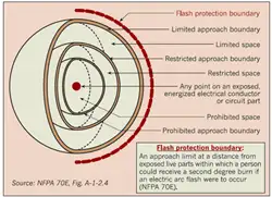
The minimum approach distance chart defines safe working distances to prevent arc flash injuries. Based on NFPA 70E and OSHA standards, it helps protect electrical workers by specifying limits by voltage level.
The Importance of the Minimum Approach Distance Chart in Electrical Safety
For instance, OSHA's Table R-6 specifies minimum approach distances for various voltage ranges, ensuring workers adhere to safe practices when operating near live electrical parts. This chart guides how close workers can safely get to energized equipment based on system voltages and other factors, ensuring compliance with safety standards such as NFPA 70E. Maintaining a safe…
View more
Why Do Arc Flashes Happen? Hazard Prevention
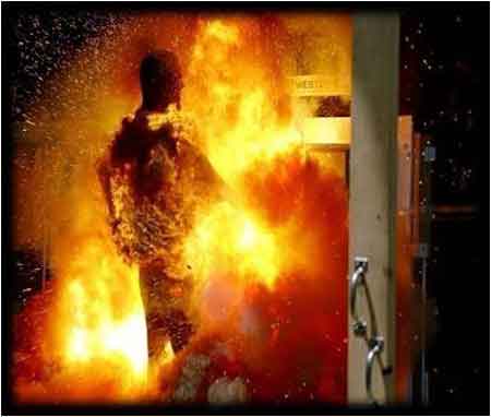
Arc flashes happen when electrical current jumps through air due to equipment failure, human error, or insulation breakdown, releasing dangerous heat, intense light, and explosive pressure that can injure workers and damage equipment.
Why Do Arc Flashes Happen?
NFPA 70E Arc Flash Training
CSA Z462 Arc Flash Training
Request a Free Training Quotation
These violent electrical events occur when an unintended path forms between energized conductors or from a conductor to the ground, allowing electricity to escape in the form of a high-energy arc. In fractions of a second, this uncontrolled discharge can generate heat exceeding 35,000°F, light brighter than…
View more
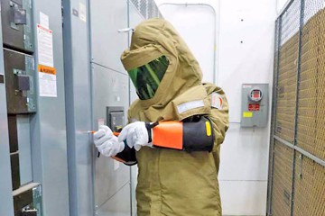
Electrical Safety Work Explained
Electrical safety work ensures risk assessment, lockout-tagout, arc-flash boundaries, PPE, grounding, and isolation procedures for switchgear and panels, meeting NFPA 70E and OSHA standards to protect technicians during maintenance, testing, and commissioning.
Why Understanding Electrical Safety Work Is Important
Electrical safety work is critical for protecting personnel and equipment in industrial and commercial environments with high voltage and electrical hazards. From arc flash risks to shock and burn injuries, working with or around energized systems demands strict adherence to safety protocols.
This includes proper training, the use of personal protective equipment (PPE), and compliance with standards such as NFPA…
View more
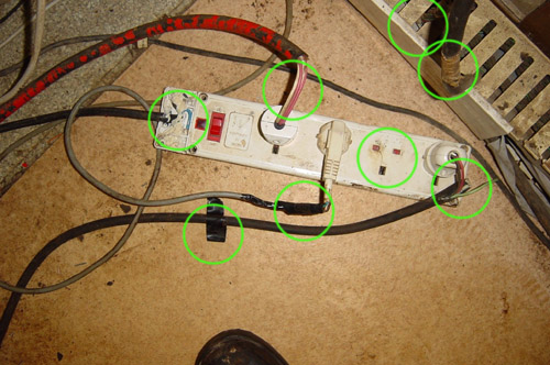
How Often Should You Inspect an Extension Cord?
Inspect extension cords before each use and after any event that could cause damage, such as rough handling, moisture exposure, or heavy electrical loads.
In practice, this means inspecting the cord each time it is picked up to ensure insulation is intact, plugs are secure, and there are no signs of overheating that could lead to shock or fire.
In most workplaces, extension cords are treated as minor accessories, pulled from a bin when power is needed and returned when the task is finished. That familiarity works against them. Cords are stepped on, pinched under doors, rolled over by carts,…
View more