Arc Flash

What is a Proper Practice for a Lockout/Tagout Situation?
Download Our FREE Arc Flash Handbook
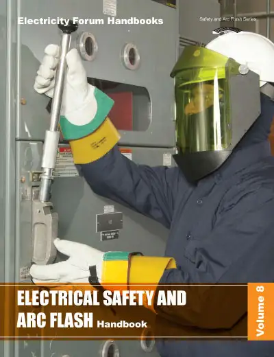
Electrical Safety and Arc Flash Handbook, Vol. 8
Your latest arc flash and electrical safety guide. 100 plus pages.
In this edition, we cover the fundamental principles of electrical safety, from risk assessments and safe work practices to the latest standards and regulations designed to protect workers from electrical injuries. We provide in-depth discussions on arc flash theory, including the causes, consequences, and methods for calculating arc flash hazards. The handbook also offers practical guidance on the implementation of safety measures, including personal protective equipment (PPE), proper labeling, and arc flash boundaries.
Volume 8 integrates industry best practices and cutting-edge solutions to help organizations develop effective safety programs and maintain compliance with national and international electrical safety standards. Through detailed case studies, risk assessment strategies, and expert advice, this handbook empowers professionals to create safer work environments, minimize electrical incidents, and improve overall workplace safety.
Latest Arc Flash Articles

Arc Blast Definition - Explosive Energy Explained
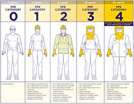
Arc Flash Categories by Voltage Chart
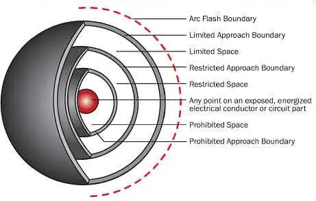
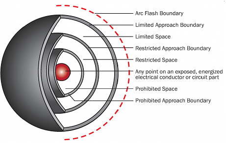
How are arc flash and electric shock protection boundaries determined?
Arc Flash Boundary Table by Incident Energy Explained
Electrical Safety Regulations Examined