Latest Electrical Protection Articles
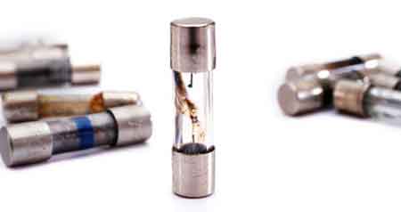
What Is a Fuse in Overcurrent Protection?
A fuse is an overcurrent protection device that melts when current exceeds safe limits, opening a circuit to prevent conductor overheating, equipment damage, and electrical fires caused by overloads or short circuits.
What is a fuse? A fuse is a sacrificial overcurrent protection device that interrupts electrical current when it exceeds a safe operating level. It contains a calibrated metal element designed to melt when excessive current flows, opening the circuit and stopping the flow of electricity before conductors, insulation, or equipment can overheat.
Because the fuse element is intentionally designed to fail first, it protects the rest of the…
View more
Sign Up for Electricity Forum’s Electrical Protection Newsletter
Stay informed with our FREE Electrical Protection Newsletter — get the latest news, breakthrough technologies, and expert insights, delivered straight to your inbox.

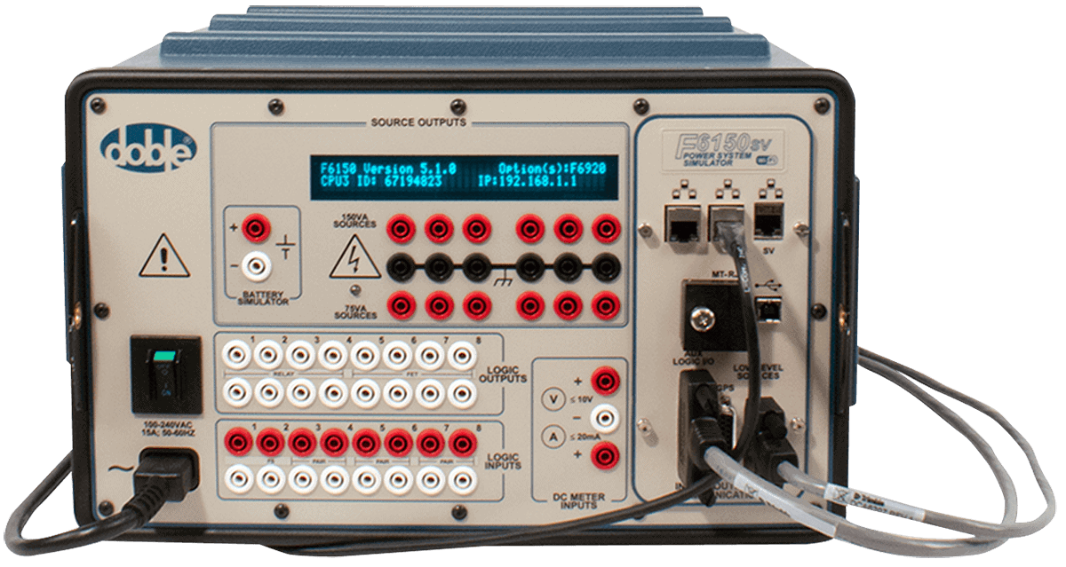
Protective Relay Testing: Verifying Protection Before It Matters
Protective relay testing verifies that installed relays will trip correctly under real fault conditions, confirming settings, timing, and logic so protection schemes operate as intended during commissioning, maintenance, and after system changes.
It is the final safeguard between a protection design that looks correct on paper and one that actually performs under fault conditions. A relay that is installed but never verified can fail silently, leaving equipment and personnel exposed when it matters most.
Protective relay testing: verifying protection before it is needed
Protective relays occupy a strange position in electrical systems. They are trusted implicitly, yet they operate…
View more
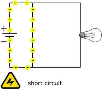
Short Circuit Analysis and Protection Limits
Short circuit analysis determines the maximum fault energy an electrical system must withstand, and the results directly determine whether protective devices will interrupt safely or fail violently. It is not a theoretical study; it is the calculation that sets interrupting ratings, coordination margins, arc-flash exposure, and ultimately whether equipment remains intact during a worst-case fault.
Engineers rely on short circuit analysis to make binding design decisions: breaker selection, relay settings, bus bracing, and equipment ratings are all constrained by the fault current values this analysis produces. If those values are underestimated, protective devices may not clear the fault. If they…
View more
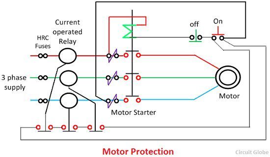
Electric Motor Protection Explained
Electric motor protection defines how motors are safeguarded against abnormal electrical, thermal, and mechanical conditions that lead to failure. It relies on coordinated protection layers to control fault energy, heat buildup, and unstable operating conditions before damage becomes permanent.
Motors rarely fail suddenly. What appears to be an unexpected breakdown is usually the final outcome of stress that has accumulated quietly over time. Slight overloads, voltage instability, phase imbalance, or repeated abnormal starts can continue for weeks while insulation and mechanical components degrade internally.
This is why electric motor protection must be treated as a system rather than a single…
View more

What Size Fuse to Use for a 30-Amp Continuous Load Explained
A 30-amp continuous electrical load requires a fuse rated at 125% of the load current, or 37.5 amps, rounded to the next standard size—typically a 40-amp fuse. This ensures safe circuit protection and compliance with NEC standards.
What Size Fuse to Use for a 30-Amp Continuous Load?
Basic Protection Relay Training
Short Circuit Study Training
Request a Free Training Quotation
Determining What Size Fuse to Use for a 30 Amp Continuous Load
A 30-amp continuous electrical load requires a fuse rated at 125 percent of its steady current—37.5 amps—rounded to the next standard size, typically 40 amps. This ensures…
View more

Electrical Surge Protection Decisions Shape System Reliability
Electrical surge protection safeguards power systems from voltage spikes, lightning strikes, and transient overvoltages. It improves reliability, extends equipment life, and ensures compliance with electrical safety and power quality standards.
Electrical Surge Protection Is a System Decision, Not a Device Choice
Electrical surge protection fails most often not because protection is missing, but because it is placed in the wrong part of the system. Facilities install surge devices but still lose drives, controls, and electronics because surge protection is treated as a product rather than a system decision. The real question is not whether surge protection exists, but whether…
View more
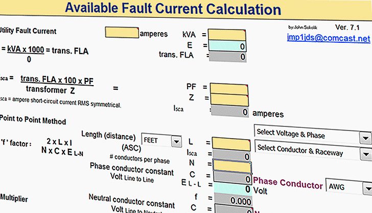
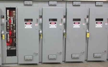
Available Fault Current in Electrical Systems
Available fault current refers to the maximum short-circuit current at a specific system point. It depends on transformer size, conductor impedance, and system capacity, and must be calculated for electrical safety, code compliance, and protective device coordination.
What matters in practice is not the number itself, but what that number silently controls. Available fault current sets the upper limit that breakers, switchgear, and assemblies must withstand during a fault. It determines whether equipment interrupts cleanly or fails under stress, whether labels reflect reality, and whether a system clears a fault predictably or violently.
For that reason, available fault current is…
View more