Latest Power Quality Articles
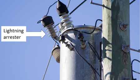
Lightning Arrester Explained
A lightning arrester protects electrical systems by diverting high-voltage surges from lightning strikes to the ground. It prevents equipment damage, ensures system reliability, and enhances safety in power transmission and distribution networks.
Lightning Arrester: Real-World Examples and Uses
Power Quality Analysis Training
Power Factor Training
Request a Free Power Quality Training Quotation
These strikes can generate immense voltage surges, capable of damaging transformers, insulators, and other critical components. For T&D professionals, understanding how it works is crucial to ensuring the reliability and safety of power networks. This article examines the fundamental aspects of lightning arresters and their crucial role in…
View more
Sign Up for Electricity Forum’s Power Quality Newsletter
Stay informed with our FREE Power Quality Newsletter — get the latest news, breakthrough technologies, and expert insights, delivered straight to your inbox.
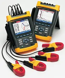
Power Quality Analyzer Selection and Compliance Accuracy
Power quality analyzer instruments determine whether voltage disturbances, harmonics, and transients are captured within IEC Class A accuracy thresholds. Sampling rate, trigger configuration, and logging resolution define evidentiary integrity, compliance defensibility, and equipment liability boundaries in industrial systems where disputed events can transfer financial responsibility.
Power quality analyzer selection is not about general electricity monitoring. It is about determining whether a disturbance can be documented with sufficient accuracy to withstand regulatory review, contractual dispute, or insurance scrutiny. The decision problem is not whether to measure, but whether the measurement will be defensible.
In industrial systems, voltage sags of less than…
View more
What is Unity Power Factor Explained
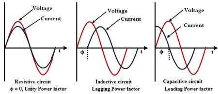
What is unity power factor? In AC circuits, it means zero reactive power, zero phase angle, maximum efficiency, real equals apparent power, ideal load, minimized losses, and optimal power triangle alignment for generators and transformers.
What Is Unity Power Factor?
Unity power factor occurs when the voltage and current waveforms in an AC electrical circuit are perfectly aligned, meaning that all electrical power supplied by the power source is effectively used by the load. Achieving this state ensures that the real power consumed by the system equals the apparent power, without any energy being wasted in reactive components. Understanding…
View more
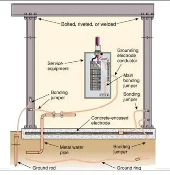
Electrical Ground Rod Installation Guide
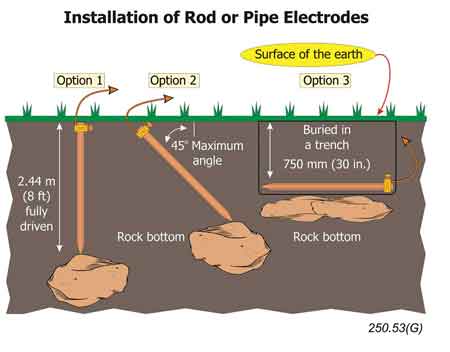
Electrical ground rod installation determines how effectively fault current, lightning energy, and surges dissipate into soil. Proper depth, spacing, bonding, soil conditions, and code-aligned placement decide whether a grounding system protects assets.
That reality is why ground rod installation is not a trivial task or a generic “how-to.” It sits at the intersection of soil behavior, conductor physics, and code intent, and its success depends as much on judgment as it does on technique.
Electrical Ground Rod Installation in Real Systems
Installing a ground rod is often treated as a procedural obligation rather than a system decision. In practice,…
View more
Surge Suppression Architecture and Transient Energy Control
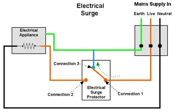
Surge suppression controls transient overvoltage from switching operations and lightning impulses. Clamping voltage thresholds, SPD coordination, discharge current ratings, and grounding impedance determine whether insulation withstand limits are exceeded in three phase systems.
Surge suppression determines whether a transient overvoltage remains within insulation coordination limits or escalates into cumulative equipment stress. In three phase systems, switching events, capacitor energization, and lightning impulses create voltage spikes that travel faster than conventional protection can respond.
Most facilities assume surge events are rare. In reality, repetitive, low amplitude impulses cause progressive dielectric degradation in control transformers, variable frequency drives, relays, and communication power…
View more
Voltage Flicker Severity Indices Framework
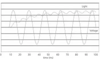
Voltage flicker becomes enforceable when Pst and Plt severity indices cross perceptibility thresholds under weak three phase grid conditions.
Voltage flicker severity is quantified through standardized perceptibility curves and IEC measurement windows that translate repetitive voltage modulation into compliance relevant indices. Under variable three phase load cycling, threshold discipline determines whether the disturbance remains operationally acceptable or escalates into regulatory exposure.
In industrial systems, flicker is not evaluated by visual observation but by statistically processed severity indices that reflect repetition rate, modulation depth, and persistence over defined aggregation intervals. The engineering decision is whether the measured disturbance exceeds structured compliance…
View more
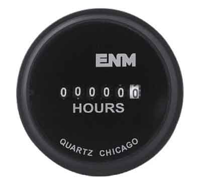
Optimizing Equipment Maintenance with Hour Meters
Optimizing Equipment Maintenance with ENM meters boosts predictive maintenance, condition monitoring, and power quality analytics, enabling IoT/SCADA integration, reliability-centered maintenance, and downtime reduction for electrical assets across industrial power systems.
Optimizing Equipment Maintenance With ENM Meters Explained for Electrical Professionals
Proper equipment maintenance is crucial for maximizing uptime, extending service life, and minimizing unexpected failures. One of the most effective tools for achieving this is the hour meter—a simple yet powerful device that tracks the duration of equipment operation. By accurately logging run-time, hour meters enable maintenance teams to schedule service intervals based on actual usage rather than relying…
View more