NEC 250.122 Explained
By Colin P. Hurst, Associate Publisher
By Colin P. Hurst, Associate Publisher
Our customized live online or in‑person group training can be delivered to your staff at your location.

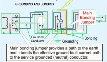
NEC 250.122 defines how to size the equipment grounding conductor (EGC) in an electrical circuit. The rule links the minimum size of the grounding conductor directly to the rating of the overcurrent protective device protecting the circuit, such as a circuit breaker or fuse. Using Table 250.122, electricians determine the minimum copper or aluminum grounding conductor required to safely carry fault current and allow the protective device to clear the fault quickly.
The equipment grounding conductor is not designed to carry normal load current. Its purpose is to provide a low-impedance return path during a ground fault, allowing sufficient current to trip the protective device. If the EGC is undersized, fault current may not rise high enough to open the breaker rapidly, allowing dangerous voltage to remain on exposed metal parts and increasing the risk of fire, equipment damage, or electric shock.
NEC 250.122 therefore ties grounding conductor sizing to fault clearing performance, not to the load current of the circuit. Understanding this relationship is essential when designing feeders, motor circuits, or branch circuits where conductor upsizing, shared raceways, or parallel runs may affect grounding conductor requirements.
NEC 250.122 ties minimum sizes for copper and aluminum equipment grounding conductors to the ampere rating of the overcurrent protective device. The table establishes a conservative baseline that assumes the grounding path must carry available fault current long enough for the protective device to operate within its time current characteristic.
Threshold discipline becomes critical when the available fault current approaches the interrupting rating of downstream devices. In facilities where the calculated available fault current exceeds 25 kA at 480 V, even small increases in grounding path impedance can delay the instantaneous trip response. That delay can elevate arc flash incident energy beyond labeling assumptions, creating cascading exposure from conductor heating to enclosure damage.
Stay informed with our FREE Power Quality Newsletter — get the latest news, breakthrough technologies, and expert insights, delivered straight to your inbox.
In high-fault-current industrial environments, grounding conductor performance must also be evaluated within the broader context of system impedance and Power Quality, because voltage distortion and fault dynamics can influence protective device response times.
When conductors are increased in size for voltage-drop control, NEC 250.122(B) requires proportional upsizing of the equipment grounding conductor in circular mil area. This scaling preserves relative impedance between ungrounded and grounded conductors. Failure to maintain proportional scaling introduces model uncertainty. The protective device may see less symmetrical fault current than assumed in coordination studies.
Long feeders serving large motors or distributed loads often require upsizing the phase conductors to control voltage drop during starting. If a 200 A feeder originally designed with 3/0 copper is increased to 350 kcmil to maintain voltage within acceptable limits during motor acceleration, proportional scaling of the grounding conductor is required unless a qualified person documents an exception basis.
The tradeoff is practical. Larger grounding conductors increase material and conduit fill while preserving low impedance during a fault. Reducing the grounding conductor to the table minimum while upsizing phase conductors reduces cost and space, yet increases impedance relative to the phase conductors. That imbalance can slow breaker response during high magnitude faults.
Facilities analyzing load behavior using Apparent Power and Three Phase Power Calculation often overlook that fault performance does not scale linearly with normal operating current. Grounding conductor impedance directly affects clearing time.
NEC 250.122(F) requires an equipment grounding conductor in each parallel raceway. The rule recognizes that fault current does not distribute evenly if only a single grounding conductor is installed. In high-fault-current systems above 35 kA, uneven sharing can overheat one raceway while leaving another underutilized.
An operational edge case arises in industrial facilities with parallel feeders supplying large adjustable-speed drives. Harmonic distortion, as evaluated under Power Quality and Harmonics, may already stress neutral and grounding conductors. During a line-to-ground fault, circulating harmonic currents combined with asymmetrical fault current can create localized thermal concentration in one grounding path.
This is where threshold discipline intersects with protection coordination. If the breaker's instantaneous pickup is set near the available fault current, added impedance from uneven grounding paths may prevent instantaneous operation and force the device into its short-time region. That shift increases I-squared t exposure and arc duration.
For motor circuits, the grounding conductor size is based on the branch-circuit protective device, not the motor's full-load current. Motor protective devices are often sized to accommodate inrush current. The equipment grounding conductor must therefore be capable of carrying fault current consistent with that higher device rating.
In large motor control centers where multiple feeders exceed 400 A, available fault current may approach 42 kA depending on transformer impedance. A grounding conductor that meets the table minimum but is installed with long, high-impedance routing can increase the effective impedance enough to delay the trip by several cycles. Each additional cycle at 480 V can materially increase arc flash energy.
Facilities that track disturbance data using Power Quality Monitoring and validate events with a Power Quality Analyzer should correlate fault clearing times with grounding path configuration. Protection misoperation investigated through Power Quality Troubleshooting frequently traces back to impedance assumptions rather than device failure.
If the equipment grounding conductor is undersized relative to fault duty, the first consequence is increased impedance. Increased impedance delays protective device operation. Delayed operation increases conductor heating and arc duration. Elevated arc duration raises incident energy and enclosure pressure. That sequence can escalate from a localized fault to equipment destruction and extended outage.
If restoration performance is treated as a board-level metric, grounding conductor sizing is no longer a drafting detail. It becomes an executive risk variable tied to outage duration and safety exposure.

A persistent deployment constraint is physical space in existing raceways. Retrofitting larger grounding conductors into legacy conduits may exceed fill limits, forcing redesign. The engineering judgment is whether to reroute, increase conduit size, or restructure feeder topology.
Inspectors must verify not only the conductor gauge but also proportional upsizing where required. Table compliance alone is insufficient when phase conductors are increased to accommodate voltage drop or system expansion.
NEC 250.122 is not a theoretical sizing exercise. It governs whether the grounding path will perform under maximum available fault current while remaining coordinated with protective devices and installation constraints. In high-energy electrical systems, that margin defines whether a fault is cleared cleanly or allowed to propagate into a cascading operational event.
Explore 50+ live, expert-led electrical training courses –