Resistance in Series Explained


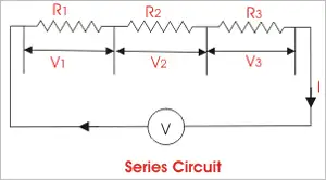
Resistance in series refers to the arrangement of individual resistors in a circuit, where the current flows through each resistor end to end. In this configuration, the total resistance (R) of the circuit is equal to the sum of the individual resistances, also known as the equivalent R.


What is Resistance in Series?

Resistance in series refers to a circuit configuration where resistors are arranged in a single path:

✅ Total resistance is the sum of all resistors in the circuit

✅ The same current flows through each resistor

✅ Voltage divides across each resistor based on its value

To calculate the total R in a series circuit, the individual resistances of each resistor are added together. The formula to calculate the equivalent resistance in a series connection is Rtotal = R1 + R2 + R3 + ..., where R1, R2, R3, and so on, represent the individual resistances of each resistor in the circuit.

Ohm's law also applies to series circuits, where the current through each resistor is the same, but the voltage across each resistor is proportional to its R. The total voltage across the series combination of resistors equals the sum of the voltage drops across each resistor.

It is essential to note that the total resistance in a series circuit is always greater than the resistance of any individual resistor in the circuit, due to the cumulative effect of each resistor's resistance.

On the other hand, resistors connected in parallel result in a parallel circuit. The equivalent R of a parallel circuit is calculated differently from a series connection. Instead of adding the individual resistances, the reciprocal of each R is added, and the resulting value is inverted to obtain the equivalent resistance.


R in Series - Parallel

When you place R-I-S, their ohmic values add up arithmetically to reach the total (or net) R.

We can connect a series of resistors (equal to the sum of the individual resistances of a parallel circuit), all having identical ohmic values, in parallel sets of series networks or series sets of parallel networks. When we do either of these things, we create a series-parallel network that can significantly increase the total power-handling capacity of the network compared to the power-handling capacity of a single parallel resistor.


Fig. 4-14. Three resistors in series. 

Sometimes, the total single equivalent R of the combination circuit in a series-parallel network equals the value of any one of the resistors. This always happens if the parallel branches or parallel combinations of the connection components are all identical and are arranged in a network called an n-by-n (or n x n) matrix. That means when n is a whole number, we have n series sets of n resistors connected in parallel, or else we have n parallel sets of n resistors connected in series in the circuit. These two arrangements yield the same practical result for electrical circuits.

A combination of series parallel combinations array of n by n resistors, all having identical ohmic values and identical power ratings, will have n2 times the power-handling capability of any resistor by itself. For example, a 3 x 3 series-parallel matrix of 2 W resistors can handle up to 32 x 2 = 9 x 2 = 18 W. If we have a 10 x 10 array of 1/2 W resistors, then it can dissipate up to 102 x 1/2 = 50 W. We multiply the power-handling capacity of each individual resistor by the total number of resistors in the matrix.

The above-described scheme works if, but only if, all of the resistors have identical ohmic values according to ohms law and identical power-dissipation ratings in terms of total voltage drops when the sum of the voltage drops across each resistor. If the resistors have values that differ even a little bit from one another, one of the components will likely draw more current than it can withstand, so that it will burn out, no matter the voltage source. Then the current distribution in the network will change further, increasing the likelihood that a second resistor will fail, and maybe more.

If you need a resistor that can handle 50 W, and a certain series-parallel connection of the network will handle 75 W, that's fine. But you should not "push your luck" and expect to get away with using a network that will handle only 48 W in the same application. You should allow some extra tolerance, say 10 per cent over the minimum rating. If you expect the network to dissipate 50W, you should build it to handle 55W or a bit more. You don't have to use "overkill," however. You'll waste resources if you cobble together a network that can handle 500W when you only expect it to cope with 50W—unless that's the only convenient combination you can make with available resistors.


Related Articles


Related News

Ampere to Ampere Hour Calculator Explained

An ampere to ampere hour calculator converts electric current (amps) to electric charge (Ah) based on time. Multiply current by time in hours to get ampere hours. It's useful for battery capacity, energy storage, and electrical system design.


What is "Ampere to Ampere Hour Calculator"?

An ampere to ampere hour calculator helps convert current flow over time into stored electrical charge.

✅ Multiply current (A) by time (h) to calculate charge (Ah)
✅ Useful for battery sizing and energy storage systems
✅ Supports electrical load and backup power planning


The Ampere to Ampere-Hour Calculator is a useful tool that allows users to estimate the capacity of a battery by converting the current supplied by an electrical device into ampere-hours (Ah). This calculation is particularly important when working with batteries, as it helps determine how long a battery can power a device based on the current it supplies and the device's usage duration. By using this calculator, you can easily convert amps to Ah and estimate the run-time for a specific battery. Understanding how voltage affects battery performance is key, and our voltage guide explains the role voltage plays in ampere-hour calculations. When calculating ampere-hours, it's important to account for voltage drop across conductors, especially in longer circuits. Use our voltage drop calculator to estimate losses and adjust your amp-hour estimations more accurately.


Frequently Asked Questions


What is an Ampere to Ampere Hour calculator, and how does it work?

This calculator helps convert the current, measured in amperes, into Ah capacity, which indicates how long a battery can supply a given current. For instance, a 100ah battery will deliver 100 ampere-hours of charge, meaning it can supply 1 ampere of current for 100 hours, or 10 amperes for 10 hours. To calculate Ah, the formula involves multiplying the current (in amperes) by the time in hours. For example, if a device draws 5 amperes for 20 hours, the result would be 100 ampere-hours. Learn how a watthour meter measures energy over time, complementing ampere-hour readings in power systems.


How do you convert amperes to ampere-hours using a calculator?

To convert amps to Ah, simply multiply the number of amperes by the number of hours the current is expected to flow. This step-by-step method is straightforward:

Ampere Hour (Ah) = Amperes (A) × Time (hours)

For example, a device drawing 5 amps for 10 hours would result in a consumption of 50 Ah. In practical applications, a 100ah battery could theoretically supply 5 amps for 20 hours before running out of charge. By following these steps, users can easily convert Ah to ensure they select the right battery for their needs. A basic understanding of watts law helps you relate amps, volts, and watts to better interpret your battery’s output.


Why is converting amperes to ampere-hours important for battery capacity calculation?

Knowing how to convert amperes to Ah is crucial in determining the capacity of a battery. It enables users to estimate the battery life of a connected device based on its current draw. This information is crucial for selecting the appropriate battery type for various applications, including powering electronic devices, off-grid systems, and backup power sources. A 100 Ah battery might be suitable for low-power consumption devices, while larger systems might require batteries with higher capacities. Knowing what ammeters measure can help you determine current flow before calculating ampere-hours.


What factors should be considered when using an Ampere to Ampere Hour calculator?

When using an Ampere to Ampere Hour Calculator, several factors can affect the accuracy of the results. These include the hour rating of the battery, which defines its capacity over a specific time period, as well as the efficiency of the battery, which can vary depending on the battery type. Additionally, environmental conditions, such as temperature, may affect the battery’s performance. It is also important to avoid common input errors, such as the “error this field is required” message, which can result from incomplete or incorrect data entry.


What are common applications of Ampere to Ampere Hour conversion in electrical systems?

Ah conversions are widely used in battery-powered devices, such as 100ah batteries for solar power systems, electric vehicles, and portable electronics. Calculating the battery Ah capacity is essential for ensuring that a battery can provide sufficient power for the required period. These conversions also help in sizing the battery system correctly and ensuring optimal performance over time. Many industries rely on these calculations for designing and managing power systems.

The Ampere to Ampere Hour Calculator is a valuable tool for converting amperes to Ah and estimating the capacity of a battery. Understanding how to calculate Ah ensures that you select the right battery type for your application, whether it’s powering an electrical device or an entire off-grid system. By considering factors like the hour rating and potential errors, you can make more informed decisions when choosing batteries for long-term use. Explore the concept of what is an ampere to understand the foundation of converting current to amp-hours in any system.


Related Articles


View more

Power System Analysis Explained

Power System Analysis enables load flow studies, fault calculations, stability assessment, state estimation, and contingency analysis for grids, integrating SCADA data, protection coordination, and reliability planning to optimize transmission, distribution, and generation performance.


What Is Power System Analysis?

Power System Analysis models grid behavior to ensure stability, reliability, efficiency, and secure operation.

✅ Load flow, short-circuit, and transient stability studies

✅ State estimation, SCADA integration, and contingency analysis

✅ Protection coordination, reliability assessment, and optimization


Power system analysis (PSA) is an essential electrical system component. It helps to ensure that the electrical system operates efficiently, reliably, and safely. Power flow analysis, fault study, stability investigation, renewable energy integration, grid modernization, and optimization techniques are all essential concepts in PSA. As our society continues to rely heavily on electricity, PSA will remain a vital tool for ensuring the stability and reliability of the electrical system. For foundational context on how electricity underpins these studies, see this primer on what electricity is and how it behaves.

One of the critical concepts in PSA is power system modelling. Modelling is creating a mathematical model of the electrical system. This model includes all the system components, such as generators, transformers, transmission lines, and distribution networks. Modelling is essential as it provides a detailed understanding of the system's workings. Engineers commonly begin by drafting a single-line diagram to visualize component interconnections and power paths.

Another critical concept in PSA is power flow investigation, also known as load flow investigation. Power flow analysis calculates the electrical system's voltages, currents, and power flows under steady-state conditions. A power flow study helps determine whether the electrical system can deliver electricity to all the loads without overloading any system component. The results of the power flow investigation are used to plan the system's expansion and ensure that it operates efficiently and reliably. In practice, load-flow outputs are interpreted within the broader context of electric power systems to validate voltage profiles and thermal limits.

Fault study is another crucial component of PSA. A fault study is a process of analyzing the system's behaviour during a fault condition. This needs a short circuit analysis. A fault is abnormal when the system has a short or open circuit. A fault study helps to determine the fault's cause and develop strategies to prevent or mitigate the effects of faults in the future.

Stability investigation is also an important aspect of PSA. Stability investigation is the process of analyzing the system's behaviour under dynamic conditions. For example, the system is subject to dynamic disturbances, such as sudden load or generator output changes, which can cause instability. Stability investigation helps ensure the system can withstand these disturbances and operate reliably.

The transient investigation is another key concept in PSA. The transient study analyzes the electrical system's behaviour during transient conditions, such as switching operations or lightning strikes. A brief investigation helps ensure the system can withstand these transient conditions and operate reliably.

Renewable energy integration is an emerging concept in PSA. As more renewable energy sources, such as wind and solar power, are integrated into the energy system, PSA becomes increasingly essential to ensure the stability and reliability of the electrical system. Understanding how generation mixes are formed benefits from a primer on how electricity is generated across thermal, hydro, and renewable technologies.

Grid modernization is also a crucial aspect of PSA. As the system ages, it becomes increasingly important to modernize the grid to ensure that it can meet the demands of modern society. Therefore, PSA is used to develop strategies to modernize the grid and ensure it operates efficiently, reliably, and safely. Many modernization roadmaps align with the evolving architecture of the electricity grid as utilities adopt automation, advanced metering, and distributed resources.

Finally, protection coordination and optimization techniques are essential components of PSA. Protection coordination involves developing strategies to protect the electrical system from faults and other abnormal conditions. Optimization techniques involve developing strategies to optimize the system's operation and ensure it operates efficiently and reliably. Because reactive power and losses affect dispatch, monitoring and improving power factor can materially enhance system efficiency.


What is power system analysis, and why is it important?

PSA analyzes the electrical system to ensure it operates efficiently, reliably, and safely. Therefore, it is crucial to identify potential problems before they occur and develop strategies to prevent or mitigate the effects of these problems. In addition, PSA is important because it helps ensure that the electrical system can meet the demands of modern society, which relies heavily on electricity.


How is power flow analysis performed?

Power flow analysis, or load flow analysis, is performed using a mathematical model. The model includes all the power system components, such as generators, transformers, transmission lines, and distribution networks. A power flow study calculates the electrical system's voltages, currents, and power flows under steady-state conditions. The results of the power flow investigation are used to plan the electrical system's expansion and ensure that it operates efficiently and reliably. These studies also quantify reactive power behavior, making concepts like what power factor is directly applicable to planning and operations.


What is fault analysis, and how is it used?

Fault analysis is analyzing the system's behaviour during a fault condition. A fault is abnormal when the system has a short or open circuit. A fault study is used to determine the fault's cause and develop strategies to prevent or mitigate the effects of faults in the future. Fault analysis is crucial in ensuring the safety and reliability of the electrical system.


What are the different stability study techniques used?

Several stability investigation techniques are used in PSA to measure transient, small-signal, and voltage stability. Transient stability is used to analyze the behaviour of the distribution under dynamic conditions, such as sudden changes in load or generator output. Small-signal stability measurement analyzes the system's behaviour under small disturbances. Finally, voltage stability measurement is used to analyze the system's behaviour under steady-state conditions and determine the system's voltage limits.


How does renewable energy integration affect power system analysis?

Renewable energy integration is an emerging concept in PSA. As more renewable energy sources, such as wind and solar power, are integrated into the electrical system, PSA becomes increasingly essential to ensure the stability and reliability of the system. Renewable energy sources are intermittent, which can cause fluctuations in the system. PSA is used to develop strategies to integrate renewable energy sources into the system while ensuring its stability and reliability.


What are the challenges of grid modernization, and how does power system analysis help overcome them?

Grid modernization is a crucial aspect of PSA. As the system ages, it becomes increasingly important to modernize the grid to ensure that it can meet the demands of modern society. Grid modernization involves upgrading the system to incorporate new technologies, such as smart grid technologies and renewable energy sources. The challenges of grid modernization include the need for new infrastructure, the integration of new technologies, and new regulatory frameworks. PSA is used to develop strategies to overcome these challenges and to ensure that the electrical system operates efficiently, reliably, and safely.


How can optimization techniques improve system efficiency and reliability in power system analysis?

Optimization techniques can be used in PSA to improve system efficiency and reliability. These techniques involve developing strategies to optimize the system's operation and ensure it operates efficiently and reliably. For example, optimization techniques can determine the optimal generation and transmission of power, improve load forecasting, and develop strategies to reduce energy consumption. PSA is crucial in developing and implementing these optimization techniques, which help improve the electrical system's overall efficiency and reliability, leading to a more sustainable and cost-effective electrical power system.


Related Articles

View more

Electricity Grid - T&D

Electricity grid infrastructure delivers power through transmission lines, substations, and smart grid controls, balancing voltage and frequency, integrating renewable energy, enabling demand response, improving reliability, and supporting utilities with real-time monitoring and load management.


What Is the Electricity Grid?

A network of transmission, distribution, and control systems that delivers reliable electrical power to consumers.

✅ Transmits high-voltage power from plants to local networks

✅ Steps down voltage at substations for safe distribution

✅ Integrates renewables with smart grid and demand response


The electricity grid is a complex and essential component of modern society. It provides the power necessary to operate homes, businesses, and industries, and it is constantly evolving to meet the demands of a changing world. From power generation to distribution, transmission lines to load balancing and renewable energy integration, every component is critical in ensuring we can access reliable and affordable energy whenever needed. For a broader primer, resources such as electric power systems outline how these elements interconnect in practice.

At its core, the grid is a system that connects power generation facilities to consumers through transmission lines and distribution systems. It is designed to move electricity from where it is generated to where it is needed, whether in a residential home or a large industrial facility. The term "grid" refers to the interconnectedness of these systems, which allows power to flow from one location to another as needed. The federal energy regulatory commission ferc regulates the grid.

In North America, the transmission and distribution (T&D) grid is managed by federal, state, provincial, and territorial agencies. The grid is divided into various regions, each with its grid operator responsible for ensuring reliable and efficient operation within their respective jurisdiction. For instance, Canada's power delivery network is divided into four main regions: Western Canada, Ontario, Quebec, and the Atlantic region. Similarly, the United States' electricity grid is divided into three major interconnected systems: the Eastern Interconnection, Western Interconnection, and the Electric Reliability Council of Texas (ERCOT) system. Each region's grid operator works closely with neighbouring grid operators to ensure a seamless flow of electrical power across the interconnected grid, even during periods of high demand or unexpected outages.

The power delivery network can be broken down into three main components: power generation, transmission, and distribution. Power generation facilities can take many forms, including coal-fired, natural gas, nuclear, and renewable energy sources such as wind and solar. These facilities generate electrical power transmitted over high-voltage transmission lines to substations, where the voltage is lowered for distribution to homes and businesses through a network of distribution lines. For those new to supply technologies, overviews of how electricity is generated cover conventional and renewable pathways.

Transmission lines are a critical component of the T&D system, which deliver and produce electricity at higher voltages. T&D provides the means to move large amounts of electrical power over long distances. These lines are typically made of high-strength steel or aluminum and span hundreds of miles. They are also designed to be highly resilient to extreme weather events such as hurricanes, tornadoes, and ice storms. Understanding ratings, capacity, and losses draws on electricity power fundamentals that inform planning and operations.

The distribution system is the final component of the power grid, responsible for delivering electrical power directly to homes and businesses. This system includes transformers, power lines, and meters, which work together to regulate power flow to individual consumers. The distribution system also includes local power generation facilities, such as rooftop solar panels and small-scale wind turbines, which can supplement the power provided by the grid. To see how fuel mixes influence local grids, summaries of sources of electricity highlight regional differences.

As the world increasingly relies on electrical power, there is a growing need to modernize and upgrade the power delivery network to meet the demands of the 21st century. One approach to this is the development of a smart grid, which uses advanced sensors, communication networks, and analytics to optimize the flow of power and improve reliability. Another approach is the integration of renewable energy sources such as wind and solar into the grid, which can reduce greenhouse gas emissions and improve grid resilience. Advanced planning and forecasting increasingly leverage power system analysis to evaluate contingencies and optimize investments.

Load balancing is another critical function, ensuring that real-time power generation and consumption are matched. This is accomplished through a combination of forecasting, automated control systems, and energy storage facilities such as batteries and pumped hydroelectric storage. In flexible markets, insights into electricity generation help operators schedule resources effectively.

Reliability and resilience are also crucial factors in its overall performance. The grid must be designed to withstand extreme weather events and other disruptions, such as cyberattacks or equipment failures. This requires a combination of robust engineering and effective emergency response planning.


What is an electricity grid, and how does it work?

A T&D system is a complex network of power generation facilities, transmission lines, and distribution systems that work together to ensure reliable and affordable energy is available to consumers. At its core, the grid is a system that connects power generation facilities to consumers through transmission lines and distribution systems. It is designed to move electrical power from where it is generated to where it is needed, whether in a residential home or a large industrial facility. The grid uses high-voltage transmission lines to move electrical power over long distances, then lowers the voltage through transformers for distribution to homes and businesses. For foundational clarity, a concise explainer on what electricity is helps connect basic concepts to grid operations.


What is the difference between the transmission and distribution systems?

The transmission system is responsible for moving large amounts of electrical power over long distances at high voltages. This is accomplished through a network of high-voltage transmission lines and substations spanning hundreds of miles. The distribution system delivers electrical power directly to homes and businesses at lower voltages. This system includes transformers, power lines, and meters, which work together to regulate the flow of electricity to individual consumers.


How is renewable energy integrated?

Renewable energy sources such as wind and solar are integrated into the T&D system through a process called interconnection. This involves connecting the renewable energy source to the grid through a substation and transformer, ensuring that the energy generated can be transmitted to consumers. Renewable energy sources can also be connected to the grid through distributed generation, where energy is generated on-site at the point of consumption, such as through rooftop solar panels.


What are the challenges associated with maintaining the reliability and resilience of the T&D system?

Maintaining reliability and resilience is a complex task requiring robust engineering and effective emergency response planning. Some of the challenges associated with this include extreme weather events, cyberattacks, equipment failures, and natural disasters. In addition, as the grid becomes more reliant on renewable energy sources, new challenges may arise related to load balancing and energy storage.


What is a smart grid, and how does it differ from a traditional T&D system?

A smart grid is a modernized version of the traditional T&D system that uses advanced sensors, communication networks, and analytics to optimize the flow of electrical power and improve reliability. Unlike a traditional T&D system, designed to move electrical power from power plants to consumers, a smart grid enables two-way communication between consumers and the grid. This allows for greater control and flexibility in managing energy usage and improved efficiency and reliability.


How can energy storage be used to support the T&D system?

Energy storage can be used to support the T&D system in several ways. One essential function is to provide backup power in the event of a blackout or other disruption to the grid. Energy storage can also help balance the load on the grid, ensuring that power generation and consumption are matched in real-time. In addition, energy storage can help integrate renewable energy sources into the grid by storing excess energy for use during times of low generation.


What is grid modernization, and why is it important for the future of the T&D system?

Grid modernization refers to upgrading and improving the T&D system to meet the demands of a changing world. This may involve the development of a smart grid, the integration of renewable energy sources, and the deployment of advanced sensors and control systems. Grid modernization is important for the future of the T&D system because it will enable greater efficiency, reliability, and sustainability while ensuring that the grid is resilient to emerging threats and challenges.


Related Articles

View more

Wattmeters – Power Measurement

Wattmeters measure electrical power in watts, monitoring energy use in industrial power systems. They provide accurate active power readings for efficiency and load management, utilizing voltage and current measurements to achieve precise results.


What are Wattmeters?

Wattmeters are instruments used to measure electrical power. They:

✅ Measure active electrical power in watts for various applications.

✅ Are used in industrial, commercial, and residential energy monitoring.

✅ Help optimize efficiency, manage loads, and ensure system safety.

A wattmeter measures instantaneous (or short-term) electrical power in watts, while a watthour meter accumulates that power over time and reports energy used (e.g. in kWh). Energy meters and smart meters extend this concept by recording consumption continuously for billing, load analysis, and energy audits.


Working Principle of Wattmeters

Electrical power is calculated using the formula:

P = E × I

Where:

  • P = Power in watts

  • E = Voltage in volts

  • I = Current in amperes

In DC circuits, watts are sometimes expressed as volt-amperes (VA). In AC circuits, wattmeters measure true (or active) power, taking into account the power factor to compensate for phase differences between voltage and current. Unlike reactive power (measured in kvar) or apparent power (measured in kVA), active power is the usable portion that does real work. This relationship is often represented in the power triangle, where vector analysis explains how apparent, reactive, and active power interact.


Construction and Internal Components

A typical wattmeter consists of two main coil assemblies:

  1. Current Coil (CC)

    • Heavy-gauge copper wire with low resistance.

    • Connected in series with the load to carry the circuit current.

  2. Voltage Coil (VC)

    • Fine-gauge wire with high resistance.

    • Connected in parallel with the load to measure voltage.

The electrodynamometer, commonly referred to as a dynamometer wattmeter, is a classic analog device that operates on the principle of a motor. The interaction between the magnetic fields of the current and voltage coils produces a torque proportional to the power, causing the pointer to move over a calibrated scale. Understanding wattmeter principles is a foundation of basic electricity training, helping learners connect theory to practical power measurement.


Figure 1 – Construction of a dynamometer wattmeter showing current and voltage coil arrangement.


Types of Wattmeters

  • Analog/Dynamometer – Durable, reliable, suited for laboratory and field measurements.

  • Digital – Higher accuracy, data logging, and integration with monitoring systems.

  • Clamp-on  – Measure power without breaking the circuit, ideal for quick diagnostics.

  • Specialized  – Designed for RF power, audio power, or other niche applications.

In three-phase systems, wattmeters are often applied in accordance with Blondel’s theorem, which specifies the number of measurement elements required in multi-phase circuits. They are frequently used in conjunction with 3 phase electricity concepts to ensure balanced load distribution and optimal system efficiency.


Fig. 2. Power can be measured with a voltmeter and an ammeter.


Measuring Power in DC and AC Circuits

In DC circuits, power measurement can be as simple as multiplying voltage and current readings from separate meters.

Example:

If a circuit operates at 117 V DC and draws 1 A, the power is:

P = 117 × 1 = 117 W

In AC systems, especially with reactive or distorted loads, a wattmeter is essential because voltage and current may not be in phase. The device automatically accounts for the phase angle, providing accurate true power readings. Advanced digital wattmeters also compensate for harmonic distortion and poor waveform quality, providing more reliable measurements than older analog designs.

By measuring energy transfer in circuits, they also relate to other power measurement instruments such as ammeters, voltmeters, and multimeters, which measure supporting parameters needed for complete electrical analysis. Accurate wattmeter readings are crucial for diagnosing performance issues in 3-phase power networks, where the relationships between voltage and current are critical. By measuring energy transfer in circuits, they help explain fundamental laws of electromagnetism, such as Ampère’s Law, which underpins the interaction between current and magnetic fields.


Fig. 2. Power can be measured with a voltmeter and an ammeter.


Practical Examples and Load Considerations

A household iron may consume 1000 W, drawing 8.55 A at 117 V.

A large heater may draw 2000 W, or 17.1 A, potentially overloading a 15 A breaker.

In industrial settings, watt meters help prevent equipment overloading, reduce downtime, and improve energy efficiency.


Modern Wattmeter Applications

Today’s wattmeters are often part of smart energy monitoring systems that:

  • Track energy consumption over time.

  • Integrate with SCADA and IoT platforms.

  • Enable predictive maintenance through power trend analysis.

  • Support compliance with energy efficiency regulations.


Accuracy, Standards, and Advanced Considerations

Measurement accuracy is a crucial factor in determining wattmeter performance. Devices are often classified by a class of accuracy, with error limits defined by international standards such as IEC, ANSI, or IEEE. Regular calibration and testing procedures ensure watt meters continue to deliver reliable results in both laboratory and field conditions.

Modern digital watt meters feature true RMS measurement, which accurately captures distorted waveforms caused by nonlinear loads. This is especially important in power systems where harmonic distortion is present. In commercial and industrial environments, accurate wattmeter data support energy audits, load analysis, and regulatory compliance, making them indispensable tools for engineers and facility managers. Wattmeter usage is closely linked to the fundamentals of electrical energy, enabling precise monitoring for efficiency and cost control.


Key Advantages of Wattmeters

  • Accurate real-time power measurement.

  • Enhanced energy management and cost savings.

  • Improved system reliability through overload prevention.

  • Compatibility with both AC and DC systems.

Wattmeters remain a vital tool for measuring and managing electrical power. Whether in a simple residential circuit, a commercial energy audit, or a high-tech industrial monitoring system, they ensure that electrical systems run efficiently, safely, and cost-effectively. As technology advances, digital and networked wattmeters continue to expand their role, integrating into smart grids and energy-optimized infrastructures. 


Related Articles


View more

Generate Electricity From Different Sources - Thermal, Nuclear, Renewable Energy

Generate electricity via power generation methods: generators, turbines, photovoltaics, fuel cells, and microgrids; optimized by inverters, AC/DC conversion, smart grid control, energy storage, high-efficiency transmission, and reliable distribution networks integration.


What Is Generate Electricity?

Generate electricity converts energy to electric power using generators, turbines, and inverters for grid supply.

✅ Electromechanical conversion with synchronous or induction generators

✅ Power electronics: rectifiers, inverters, MPPT, AC/DC conversion

✅ Sources: PV, wind, hydro, gas turbines; grid-tied or microgrid


There are several ways to generate electricity. There are "thermal" methods like coal, oil, natural gas, peat, biomass - in all these cases, the energy that is trapped in the form of carbon (found in the ground in the form of fossil fuels) is released by heating the carbon. The problem, as we all know too well, is that the breakdown of carbon through burning it is the by product of gases such as carbon dioxide, a main contributor to global warming. But that is not all. When we burn carbon, there are other pollutants that are released into the atmosphere like sulphur dioxide and nitrous oxide. These chemicals are the principal contributors to acid rain. For a broader overview of these processes, see how electricity generation works across different fuel types.

We also produce electricity by non-fossil fuel methods by using uranium in nuclear fission "reactors" to create enough heat to boil water, which in turn produces large quantities of high pressure steam. This steam turns a turbine which turns a generator that manufactuers electic power through the conversion of mechanical energy into electrical energy. This sequence illustrates how electricity is generated from thermal sources in practice.

There is more than one renewable source of energy to generate electricity, by using solar panels to convert sunlight and wind energy to convert kinetic energy into electric power. In any case dependable power generation, transmission and distribution is critical for providing heat, light and power for human activities. Electric power has been generated for the purpose of powering human technologies for at least 120 years from various sources of potential energy. The first power plants were run on wood, while today we rely mainly on oil, natural gas, coal, hydroelectric and nuclear power and a small amount from hydrogen, solar energy, tidal harnesses, wind generators, and geothermal sources. Many utilities are expanding portfolios with alternative electricity options to meet emissions targets.


Methods To Produce Electric Power

Understanding the landscape of sources of electricity helps frame the methods described below.

Rotating turbines attached to electrical generators produce most commercially available electricity. Turbines may be driven by using steam, water, wind or other fluids as an intermediate energy carrier. The most common usage is by steam in fossil fuel power plants or nuclear power plants, and by water in hydroelectric dams. Alternately, turbines can be driven directly by the combustion of natural gas or oil. Combined cycle gas turbine plants offer efficiencies of up to 60%. They generate power by burning natural gas in a gas turbine and use residual heat to generate additional electric power from steam. Wind turbines create power by using the wind. Solar updraft towers use wind that is artificially produced inside the chimney by heating it with sunlight. Solar parabolic troughs and solar power towers concentrate sunlight to heat a heat transfer fluid that is used to produce steam to turn a turbine. In all these configurations, the core electricity generator converts rotational energy into electrical output.

Within wind applications, the modern electricity windmill integrates power electronics and control systems to maximize capacity factor.

Small power generators are often powered by reciprocating engines burning diesel, biogas or natural gas. Diesel engines are often used to create power, usually at low voltages. Biogas is often combusted where it is produced, such as a landfill or wastewater treatment plant, with a reciprocating engine or a microturbine, which is a small gas turbine. These distributed assets play a growing role in overall electricity production for remote sites and microgrids.


Related Articles

View more

Understanding Current

Current is the flow of electric charge in circuits, defined by amperage, driven by voltage, limited by resistance, described by Ohm’s law, and fundamental to AC/DC power systems, loads, conductors, and electronic components.


What Is Current?

Current is charge flow in a circuit, measured in amperes and governed by voltage and resistance.

✅ Measured in amperes; sensed with ammeters and shunts

✅ Defined by Ohm’s law: I = V/R in linear resistive circuits

✅ AC alternates; DC is steady; sets power transfer P = V*I


Current is best described as a flow of charge or that the charge is moving. Electrons in motion make up an electric current. This electric current is usually referred to as “current” or “current flow,” no matter how many electrons are moving. Current is a measurement of a rate at which a charge flows through some region of space or a conductor. The moving charges are the free electrons found in conductors, such as copper, silver, aluminum, and gold. The term “free electron” describes a condition in some atoms where the outer electrons are loosely bound to their parent atom. These loosely bound electrons can be easily motivated to move in a given direction when an external source, such as a battery, is applied to the circuit. These electrons are attracted to the positive terminal of the battery, while the negative terminal is the source of the electrons. The greater amount of charge moving through the conductor in a given amount of time translates into a current. For a concise overview of how moving charges create practical circuits, see this guide to current electricity for additional context.


The System International unit for current is the Ampere (A), where


That is, 1 ampere (A) of current is equivalent to 1 coulomb (C) of charge passing through a conductor in 1 second(s). One coulomb of charge equals 6.28 billion billion electrons. The symbol used to indicate current in formulas or on schematics is the capital letter “I.” To explore the formal definition, standards, and measurement practices, consult this explanation of the ampere for deeper detail.

When current flow is one direction, it is called direct current (DC). Later in the text, we will discuss the form of current that periodically oscillates back and forth within the circuit. The present discussion will only be concerned with the use of direct current. If you are working with batteries or electronic devices, you will encounter direct current (DC) in most basic circuits.

The velocity of the charge is actually an average velocity and is called drift velocity. To understand the idea of drift velocity, think of a conductor in which the charge carriers are free electrons. These electrons are always in a state of random motion similar to that of gas molecules. When a voltage is applied across the conductor, an electromotive force creates an electric field within the conductor and a current is established. The electrons do not move in a straight direction but undergo repeated collisions with other nearby atoms. These collisions usually knock other free electrons from their atoms, and these electrons move on toward the positive end of the conductor with an average velocity called the drift velocity, which is relatively a slow speed. To understand the nearly instantaneous speed of the effect of the current, it is helpful to visualize a long tube filled with steel balls as shown in Figure 10-37. It can be seen that a ball introduced in one end of the tube, which represents the conductor, will immediately cause a ball to be emitted at the opposite end of the tube. Thus, electric current can be viewed as instantaneous, even though it is the result of a relatively slow drift of electrons. For foundational concepts that connect drift velocity with circuit behavior, review this basic electricity primer to reinforce the fundamentals.

Current is also a physical quantity that can be measured and expressed numerically in amperes. Electric current can be compared to the flow of water in a pipe. It is measureda at the rate in which a charge flows past a certain point on a circuit. Current in a circuit can be measured if the quantity of charge "Q" passing through a cross section of a wire in a time "t" (time) can be measured. The current is simply the ratio of the quantity of charge and time. Understanding current and charge flow also clarifies how circuits deliver electrical energy to perform useful work.


Electrical current is essentially an electric charge in motion. It can take either the form of a sudden discharge of static electricity, such as a lightning bolt or a spark between your finger and a ground light switch plate. More commonly, though, when we speak of current, we mean the more controlled form of electricity from generators, batteries, solar cells or fuel cells.  A helpful overview of static, current, and related phenomena is available in this summary of electricity types for quick reference.

We can think of the flow of electrons in a wire as the flow of water in a pipe, except in this case, the pipe of water is always full. If the valve on the pipe is opened at one end to let water into the pipe, one doesn't have to wait for that water to make its way all the way to the other end of the pipe. We get water out the other end almost instantaneously because the incoming water pushes the water that's already in the pipe toward the end. This is what happens in the case of electrical current in a wire. The conduction electrons are already present in the wire; we just need to start pushing electrons in one end, and they start flowing at the other end instantly. In household power systems, that push on conduction electrons alternates in direction as alternating current (AC) drives the flow with a time-varying voltage.


Current Formula

Current is rate of flow of negatively-charged particles, called electrons, through a predetermined cross-sectional area in a conductor.

 Essentially, flow of electrons in an electric circuit leads to the establishment of current.

q = relatively charged electrons (C)

t = Time

Amp = C/sec

Often measured in milliamps, mA


Related Articles

View more

Sign Up for Electricity Forum’s Newsletter

Stay informed with our FREE Newsletter — get the latest news, breakthrough technologies, and expert insights, delivered straight to your inbox.

Electricity Today T&D Magazine Subscribe for FREE

Stay informed with the latest T&D policies and technologies.
  • Timely insights from industry experts
  • Practical solutions T&D engineers
  • Free access to every issue

Download the 2025 Electrical Training Catalog

Explore 50+ live, expert-led electrical training courses –

  • Interactive
  • Flexible
  • CEU-cerified