Types of Resistors

By R.W. Hurst, Editor


Types of Resistors

Types of resistors are essential in electronics, as they control current, reduce voltage, and ensure circuit stability. From fixed and variable resistors to specialized forms like thermistors and photoresistors, each type plays a critical role in electrical engineering.


What are the Various Types of Resistors?

Types of resistors describe categories of electronic components designed to limit current and manage voltage in circuits."
✅ Fixed resistors ensure stable resistance values

✅ Variable resistors adjust resistance as needed

✅ Specialized resistors respond to heat or light


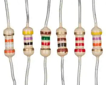
There are two main types of resistors: fixed and variable. Fixed resistors maintain a constant value, while variable resistors can be adjusted to suit changing requirements. Within these groups are many designs crafted from various materials, each selected for its precision, stability, and suitability in specific applications. When studying how different resistor types perform, it helps to review Ohm’s Law Formula, which explains the mathematical relationship between voltage, current, and resistance.

In addition to resistors, other passive components, such as capacitors, are equally important for controlling current flow and stabilizing electrical circuits.


Common Types of Resistors

Type Key Feature Typical Use
Carbon Film Low cost, general use Everyday electronics
Metal Film High accuracy, low noise Precision circuits
Metal Oxide Surge resistant Power supplies
Wire-Wound High power handling Industrial applications
Surface-Mount (SMD) Compact, space-saving Modern circuit boards
Potentiometer Adjustable resistance Volume/tuning controls
Thermistor Temperature-sensitive Sensors, protection devices


Fixed Types of Resistors


Carbon Film Resistors

Carbon film resistors are inexpensive, reliable, and widely used in general-purpose electronics. By applying a thin carbon layer to a ceramic base, they provide a stable resistance for everyday circuits. While not as precise as modern designs, they remain popular where high accuracy isn’t required.


Carbon Composition Resistors

Once the standard in consumer electronics, carbon composition resistors are now less common, but they still serve in circuits that need high pulse load capacity. They offer durability in the face of sudden surges, although their long-term stability and accuracy are lower than those of newer types.


Metal Film Resistors

Metal film resistors, made by depositing a nickel-chromium alloy onto a ceramic substrate, are prized for their precision. With excellent stability, low noise, and tight tolerances, they are widely chosen for high-frequency and sensitive applications. However, they cannot dissipate as much power as wire-wound resistors and are vulnerable to strong surges.


Metal Oxide Resistors

Using oxides like tin or ruthenium on ceramic, metal oxide resistors are known for their robustness. They combine good tolerance with the ability to withstand high voltages, making them ideal where surge protection is essential. While not as accurate as metal film resistors, they offer higher reliability in demanding conditions.


Wire-Wound Resistors

Built from coiled metal wire wrapped around a ceramic or fibreglass core, wire-wound resistors excel in high-power applications. Their ability to handle large currents and high temperatures makes them indispensable in heavy-duty circuits. Their main drawback is bulk, and at high frequencies, their inductance can interfere with performance.


Metal Strip (Foil) Resistors

Metal strip or foil resistors deliver the highest accuracy and stability, with tolerances as fine as 0.005%. Their precision makes them the component of choice in measurement instruments and high-end electronics. Their primary downsides are cost and limited power dissipation, which restrict their use in everyday applications.


Thick and Thin Film Resistors

Produced by different deposition techniques, thick and thin film resistors serve specialized roles. Thick film designs are durable and suited to power electronics and automotive systems, while thin film types offer high accuracy and stability in precision or high-frequency circuits.


Surface-Mount Resistors (SMDs)

Surface-mount resistors are compact components soldered directly onto printed circuit boards. They make modern electronics smaller and more efficient, and although tiny, they cover a wide range of resistance values to support everything from consumer devices to industrial controls.


Variable Types of Resistors

Engineers often use practical examples to compare the unit of electrical resistance with how resistors function in series and parallel arrangements.

Potentiometers

Potentiometers are adjustable resistors that allow manual control over current or voltage. They are common in volume dials, tuning controls, and adjustable circuits where user input is required.


Light-Dependent Resistors (LDRs)

LDRs change resistance with varying light levels, making them useful in light sensors, alarms, and automatic lighting systems.


Thermistors

Thermistors alter resistance with temperature. Positive temperature coefficient (PTC) types increase resistance as they heat, protecting circuits from over-current, while negative temperature coefficient (NTC) types reduce resistance with rising temperature, making them useful for sensing and regulation.

When considering the various types of resistors, they may be simple components, but their diversity makes them essential to every circuit. Whether precision, power handling, or responsiveness to environmental changes is needed, there is a resistor designed for the task. Selecting the right one ensures accuracy, stability, and safety in electronic design.


Related Articles


Related News

Kirchhoff's Law

Kirchhoff's Law, comprising the Current Law (KCL) and Voltage Law (KVL), governs electrical circuits by ensuring charge conservation and energy balance, essential for analyzing current flow, voltage drops, and network behaviour.


What is Kirchhoff's Law?

Kirchhoff's law is an essential principle in the analysis of electrical circuits, enabling a comprehensive understanding of the behaviour of complex circuits.

✅ Defines relationships between currents and voltages in electrical circuits

✅ Ensures conservation of charge (KCL) and energy (KVL) in networks

✅ Essential for analyzing and solving complex circuit problems

It consists of two fundamental rules, Kirchhoff's Current Law (KCL) and Kirchhoff's Voltage Law (KVL), which are intrinsically linked to other electricity laws, such as Ohm's law.  Kirchhoff’s Law works closely with Ohm’s Law Formula to calculate voltage drops, currents, and resistance in electrical networks.

Kirchhoff's Current Law (KCL) - Also known as the first Kirchhoff's law or Kirchhoff's junction rule, KCL states that the sum of the currents entering a junction in a circuit is equal to the sum of the currents leaving the junction. Mathematically, it can be expressed as:

ΣI_in = ΣI_out

KCL is based on the principle of the conservation of charge, asserting that charge can neither be created nor destroyed. In practical terms, KCL means that, at any given point in a circuit, the total current entering must equal the total current leaving, ensuring a continuous flow of electric charge. Understanding Basic Electricity provides the foundation for applying Kirchhoff’s Current Law and Voltage Law to real-world circuit analysis.

Kirchhoff's Voltage Law (KVL) - Also known as the second Kirchhoff's law or Kirchhoff's loop rule, KVL states that the sum of the voltage gains and losses (potential differences) around any closed loop in a circuit is zero. Mathematically, it can be expressed as:
ΣV_rise = ΣV_drop

KVL is based on the principle of the conservation of energy, indicating that energy cannot be created or destroyed but can only be converted from one form to another. In electrical circuits, KVL implies that the total voltage supplied in a loop equals the total voltage drop across all components, ensuring that energy is conserved. Accurate circuit calculations require a clear grasp of Electrical Resistance and how it impacts voltage distribution across components.


Relation to Other Electricity Laws

The most significant connection between Kirchhoff's and other electricity laws is Ohm's law, which defines the relationship between voltage, current, and resistance in an electrical circuit. Ohm's law can be expressed as:

V = IR

When analyzing a circuit using Kirchhoff's laws, Ohm's law is often employed to calculate unknown quantities such as voltage drops, currents, or resistance values. By combining Kirchhoff's laws with Ohm's law, a complete understanding of the behaviour of electrical circuits can be achieved, facilitating efficient design, troubleshooting, and optimization. Applying Kirchhoff’s principles is easier when you understand key Electrical Terms used in engineering and troubleshooting.


History

Gustav Robert Kirchhoff, a German physicist, made significant contributions to understanding electrical circuits by establishing two fundamental laws: Kirchhoff's Voltage Law (KVL) and Kirchhoff's Current Law (KCL). These laws are essential tools for circuit analysis, enabling engineers to design and troubleshoot electrical networks efficiently. In addition to resistance, Capacitance plays a vital role in determining circuit behavior, especially in AC systems.

KVL, also known as the loop rule, states that the algebraic sum of all the voltages around a closed loop equals zero. This principle is derived from the conservation of energy, which ensures that no energy is lost within a closed system. In essence, KVL states that the energy supplied to a circuit is equal to the energy consumed by the components in that circuit. Therefore, when solving problems using KVL, it is essential to consider voltage drops across resistive elements like resistors and voltage rises due to sources like batteries or generators.

On the other hand, KCL, or the junction rule, states that the algebraic sum of currents entering a junction (node) in a circuit is equal to the sum of currents leaving the same junction. This law is a consequence of the conservation of charge, which posits that charge cannot be created or destroyed within an electrical circuit. KCL ensures that the total charge entering and leaving a node remains constant, with the currents (I1, I2, I3, I4, I5) balancing each other. Knowledge of Voltage Drop is essential when using KVL to assess energy losses in electrical circuits.

The significance of these laws in electrical networks lies in their versatility, as they can be applied to a wide range of circuits, from simple series and parallel circuits to more complex electrical networks. Kirchhoff's laws can be employed in conjunction with Ohm's Law, which states that the current through a conductor is proportional to the voltage across it and inversely proportional to its resistance. Using Kirchhoff's and Ohm's Law, engineers can analyze various aspects of a circuit, including voltage drops, current flow, and power distribution.

When analyzing series and parallel circuits, his laws offer valuable insight into the behaviour of electrical components. In series circuits, the current remains constant throughout the entire loop, while the voltage drops across each resistor are proportional to their respective resistances. The voltage across each branch is constant in parallel circuits, but the current is divided among the parallel resistors according to their resistances. By applying KVL and KCL to these configurations, engineers can determine the optimal arrangement of components for a given application.

To illustrate the application of his laws, consider a simple example. Imagine a circuit with a battery, two resistors in series, and a capacitor in parallel with the second resistor. By applying KVL and KCL, we can determine the voltage drop across each resistor, the current flow through each branch, and the voltage across the capacitor, enabling us to analyze the circuit's behaviour under various conditions.

Despite their usefulness, his laws have some limitations and assumptions. For instance, they assume that the components in a circuit are ideal, meaning they have no internal resistance or capacitance. Additionally, they don't account for the effects of electromagnetic fields or the finite speed of signal propagation in AC circuits. However, these limitations are often negligible in many practical applications, as they only marginally impact circuit performance. For a deeper historical context, explore the History of Electricity and the contributions of Gustav Kirchhoff to modern circuit theory.


Related Articles


View more

Electricity Deregulation Explained

Electricity deregulation enables competitive energy markets, retail choice, and wholesale power pricing, separating generation from transmission and distribution to enhance grid reliability, lower tariffs, spur innovation, and diversify suppliers for industrial and commercial loads.


What Is Electricity Deregulation?

Electricity deregulation unbundles utilities, enabling market-based generation, retail choice, and efficient pricing.

✅ Unbundles generation, transmission, and distribution functions.

✅ Enables locational marginal pricing and demand response programs.

✅ Promotes independent system operators and competitive wholesale markets.


In The United States, Electricity Deregulation is now more than 15 years into an experiment to deregulate and restructure the electric power generation, transmission and distribution industry. Some claim that it has produced national benefits as much as $30 billion per year. Others claim the change has resulted in penalties as high as $30 billion per year. And still others point to major declines in reliability and increased frequency of blackouts. For context, resources like what electricity is can clarify foundational terms before policy comparisons.

Why are there such broad disagreement about the impact? How do the results of deregulation and restructuring compare with predictions? Has the change benefited our industrial or commercial users, ordinary consumers and our national economy? To determine the answers to these questions, the key changes that were implemented must be reviewed. A primer on electric power systems helps frame how generation, transmission, and distribution interact under different market rules.

The nature of electric power systems requires significant investments in major facilities, typically costing from tens of millions to billions of dollars. These facilities have long construction lead-times, taking years from start to completion, and often remain in service for as long as 40 years. Regulation provided for the return of the investment (depreciation) and the return on the investment (earnings) over the facilities lifetime. These cost-recovery structures ultimately filter into electricity prices that customers see on their bills.

The systems were interconnected to take advantage of the diversity in times of peak use and in times of equipment failures and emergencies. The industry focus was on long-term cost minimization. Decisions were based on life-cycle cost analyses. In such an environment, a high degree of cooperation developed among those involved in owning, managing, planning and operating electric power systems2. The national savings from this cooperation and interconnection were carefully studied many times and had increased to nearly $20 billion annually3 by the late 1980s. Prices to consumers, controlled by state regulators, were reduced by these savings. Such regional coordination also stabilizes electricity supply during peak seasons and emergencies.

Many supporters of this and the introduction of competition into the electric power business believed it would lead to significant economic benefits and price reductions to consumers. The move to have competition replace government regulation gained many adherents, particularly in large industry, where there were concerns over growing foreign competition; with economists in the nation's universities, who welcomed an opportunity to apply their theories; by investment bankers, who saw the huge fees they would earn to finance numerous buyouts and mergers; by lawyers, accounting organizations and some engineers, who saw increased business; and by entrepreneurs, who saw opportunities for huge profits. Some utility executives believed competition would help increase the return to investors that had, at times, been unfairly limited by regulators. Advocates often cited gains in electricity power market efficiency as proof that liberalization could unlock innovation.

In general, those favouring Electricity Deregulation and competition as a driver were not aware of its effect on the benefits of coordination. Most lacked knowledge of power systems functioning and costs. The concept that profits would increase for the suppliers while prices would go down for consumers obviously required major cost reductions. But no analyses of the source of these cost reductions were conducted by competent engineers. Rather, it was the common belief they would result from increased competition. They sometimes conflated consumer-level tactics like how to save electricity with systemic cost drivers in bulk power operations.

Have such cost reductions occurred? The answer is clearly no. There have been some improvements in generator unit availability and efficiency. On the other hand, there have been huge additional costs and cost increases stemming from the reduced benefits of coordination, the increased complexity of the system, scheduling, and other operating procedures. For end users, focusing on saving electricity can mitigate bill impacts even as market-level costs fluctuate.


Related Articles

View more

Sources of Electricity Explained

Sources of electricity include fossil fuels, nuclear power, and renewable energy like solar, wind, and hydro. These energy sources provide reliable electricity generation, powering homes, industries, and grids while shaping modern energy systems and sustainability goals.


What are the Sources of Electricity?

Sources of electricity are the various energy systems used to generate electrical power, ranging from conventional fuels to renewable technologies.

✅ Include fossil fuels, nuclear power, and renewable energy

✅ Used in electricity generation across all sectors

✅ Impact cost, sustainability, and environmental footprint

In the modern world, electricity plays a crucial role in our daily lives. As a result, it has become an essential commodity, from powering our homes to running industries. But have you ever wondered where it comes from? Electric power can be generated from various sources with unique characteristics, benefits, and drawbacks. In this article, we'll delve into the main sources of electric power generation and discuss their environmental impacts, costs, and efficiency. Renewable sources, such as hydro, solar, and wind, contrast with alternative electricity options that aim to reduce dependence on fossil fuels.

The primary sources of electric power used to produce electric power can be broadly categorized into renewable and non-renewable resources. Renewable energy sources, such as solar, wind, hydroelectric, geothermal, and biomass, are replenished naturally and have a lower environmental impact than non-renewable sources. Non-renewable energy sources include fossil fuels such as coal, natural gas, and oil, as well as nuclear energy. These resources are finite, and their extraction and utilization contribute to environmental issues like air pollution and climate change. Hydroelectric dams, wind turbines, and solar farms all contribute to global electricity generation, reducing reliance on non-renewable sources.

According to the U.S. Energy Information Administration, global electricity production relies on a mix of renewable and non-renewable sources. While traditional thermal power plants, fueled by coal, natural gas, and nuclear energy, remain central to electricity generation, the rapid growth of solar photovoltaics is transforming how we create and consume electricity. Many nations are investing heavily in utility-scale electricity projects, from massive solar farms to offshore wind facilities, to meet rising demand while reducing emissions. These shifts illustrate how diverse technologies collectively shape the future of reliable and sustainable power.


Fossil Fuels: The Traditional Backbone

Fossil fuels remain the dominant source of electricity worldwide. In 2023, they accounted for roughly 61% of global power generation. In the U.S., about 60% of electric power still comes from coal, natural gas, and oil. These fuels are burned to produce heat, which converts water into steam that drives turbines to generate electric power.

While fossil fuels offer reliability and established infrastructure, they release large amounts of greenhouse gases, contributing significantly to air pollution and climate change.


Nuclear Energy: Low Carbon but Controversial

Nuclear energy provides approximately 9% of the world's electric power and nearly 19% in the United States. It works by splitting atoms (nuclear fission) to release energy that turns water into steam, which then drives turbines.

Nuclear power is highly efficient and emits no carbon during operation. However, it poses concerns regarding radioactive waste, high capital costs, and the potential for catastrophic failures.


Renewable Energy: The Fastest-Growing Sector

Renewable energy sources are expanding rapidly due to technological advances and falling costs. In 2023, they accounted for approximately 30% of global electric power, with wind and solar energy experiencing the fastest growth. Among renewables, Geothermal Electricity harnesses Earth’s internal heat to produce reliable baseload power even in regions with limited solar or wind potential.


Solar Power

Solar energy converts sunlight into electric power using photovoltaic cells, also known as photovoltaic panels. It's scalable, from rooftop systems to massive solar farms, and has seen significant cost reductions over the past decade.


Wind Power

Wind turbines capture kinetic energy from the wind to generate electric power. Wind farms are increasingly common in the U.S., Europe, and China. Like solar energy, wind energy is intermittent, but storage technology is continually improving.


Hydroelectric Power

Hydroelectricity uses flowing water to turn turbines. It's the most established renewable source and provides reliable base-load power. However, large dams can disrupt ecosystems and displace communities. Hydroelectricity stands out as a mature and stable form of renewable generation, as detailed on our Hydroelectricity page.


Geothermal and Biomass

Geothermal taps into Earth’s internal heat, while biomass burns organic material. While smaller in scale, both contribute to energy diversity and localized solutions. Geothermal power generation complements solar, wind, and hydroelectric sources by offering a steady, round-the-clock output, as explained in our detailed guide on Geothermal Electricity.


Comparing Sources of Electricity

Source Global Share (2023) U.S. Share (2023) Key Advantages Key Drawbacks
Fossil Fuels ~61% ~60% Reliable, established infrastructure High emissions, non-renewable
Nuclear ~9% ~19% Low carbon, high efficiency Radioactive waste, high cost
Renewables ~30% ~21% Clean, sustainable, fast-growing Intermittent, resource/location dependent


The diverse world of electric power choices offers a range of technologies that can help meet the growing global demand for energy. By understanding the characteristics, environmental impacts, costs, and efficiencies of these sources, we can make informed decisions about transitioning to cleaner, more sustainable energy systems. As renewable energy technologies continue to advance and energy storage solutions mature, the future of electric power generation is likely to be increasingly dominated by clean, sustainable sources that reduce our impact on the planet and provide reliable power for future generations.


Environmental Impact and Efficiency

The environmental effects of each source vary significantly:

  • Coal and oil are the dirtiest, producing the most CO2 and pollutants.

  • Natural gas emits less CO2 but still contributes to climate change.

  • Nuclear has a low operational footprint but long-term waste issues.

  • Solar and wind energy produce no emissions during use, although manufacturing has some environmental impact.


Efficiency also differs:

  • Natural gas plants can achieve thermal efficiencies exceeding 60%.

  • Nuclear reactors are highly efficient, but they are slow to build.

  • Coal is among the least efficient.

  • Renewables vary based on technology and location.


Cost Considerations

Costs are influenced by technology, fuel, geography, and infrastructure:

  • Solar and wind costs have dropped dramatically, making them competitive with fossil fuels.

  • Nuclear has high upfront costs but low operating costs.

  • Fossil fuels fluctuate in response to changes in market supply and demand.


Future Trends in Power Generation

The energy sector is moving toward decarbonization. Key trends include:

  • Growth in solar and wind capacity

  • Advances in energy storage systems

  • Development of smart grids and microgrids

  • Investment in fusion energy research

Many countries are setting net-zero goals, aiming for cleaner and more sustainable electricity systems.

Electric power can be generated from various sources, each with its trade-offs in terms of cost, efficiency, and environmental impact. While fossil fuels still dominate, the momentum is clearly shifting toward renewable energy sources. A diversified energy mix, supported by smart technologies and forward-looking policies, will power the sustainable future. To understand how energy sources are converted into power, refer to our 'Generate Electricity' article, which describes the entire process from fuel or resource to grid delivery.

Understanding the strengths and weaknesses of each source helps shape a more resilient, efficient, and eco-friendly power generation landscape. Whether from fossil fuels, nuclear, or renewables, every source of electricity must connect to the electricity grid to deliver power where it is needed.


Related Articles


View more

Electricity Safety Explained

Electricity safety in electrical engineering prioritizes grounding, insulation coordination, overcurrent protection, arc-flash mitigation, lockout/tagout, and PPE to reduce shock, burn, and fire hazards in high-voltage and low-voltage installations through standards compliance and risk assessment.


What Is Electricity Safety?

Electricity safety is engineering practice to prevent shock, arc flash, and fire through design, controls, and standards.

✅ Implement grounding/earthing, bonding, and insulation coordination.

✅ Use overcurrent, residual current, and arc-fault protection.

✅ Apply NFPA 70E/IEC 60364, lockout/tagout, and arc-flash PPE.


Electricity Safety dangers involving voltages of greater than 50V are capable of producing heart fibrillation if they produce electric currents in body tissues which happen to pass through the chest area. The electrocution danger is mostly determined by the low conductivity of dry human skin. If skin is wet, or if there are wounds, or if the voltage is applied to electrodes which penetrate the skin, then even voltage sources below 40 V can be lethal if contacted. A DC circuit may be especially dangerous because it will cause muscles to lock around the wire. For a broader overview of common electrical hazards, the guide at dangers of electricity explains mechanisms of shock and injury.

Accidental contact with high voltage will usually result in severe injury or death. This can occur as a person's body provides a path for current flow causing tissue damage and heart failure. Other injuries can include burns from the arc generated by the accidental contact. These can be especially dangerous if the victims airways are affected. Injuries may also be suffered as a result of the physical forces exerted as people may fall fall from height or be thrown considerable distance. For context on regulatory and industry thresholds, see what is considered high voltage and how those limits are defined.


Electricity Safety

Depending on the short circuit current available at a switchgear line-up, a hazard is presented to maintenance and operating personnel due to the possibility of a high-intensity electric arc. Maximum temperature of an arc can exceed 10,000 kelvin, and the radiant heat, expanding hot air, and explosive vaporization of metal and insulation material can cause severe injury to unprotected workers. Such switchgear line-ups and high-energy arc sources are commonly present in electric power utility substations and generating stations and power lines, industrial plants and large commercial buildings. In the United States the National Fire Protection Association, has published a guideline standard NFPA 70E for evaluating and calculating arc flash hazard, and provides standards for the protective clothing required for electrical workers exposed to such hazards in the workplace. And even then, workers must still be careful. Understanding fault energy begins with the basics of a short circuit and how fault paths escalate incident energy.

While arc flash and arc blast are distinct, an arc fault can originate from insulation breakdown or wiring damage and quickly intensify conditions.


Explosion hazard

Even voltages insufficient to break down air can be associated with enough energy to ignite atmospheres containing flammable gases or vapours, or suspended dust. For example, air containing hydrogen gas or natural gas or gasoline vapor can be ignited by sparks produced by electrical apparatus fed by electricity lines or electricity power lines. Examples of industrial facilities with hazardous areas are petrochemical refineries, chemical plants, grain elevators, and some kinds of coal mines. In many environments, seemingly minor static electricity discharges are sufficient to ignite vapors if controls are inadequate.

Measures taken to prevent such explosions include:

  • Intrinsic safety, which is apparatus designed to not accumulate enough stored energy to touch off an explosion
  • Increased safety, which applies to devices using measures such as oil-filled enclosures to prevent contact between sparking apparatus and an explosive atmosphere
  • Explosion-proof enclosures, which are designed so that an explosion within the enclosure cannot escape and touch off the surrounding atmosphere (this designation does not imply that the apparatus will survive an internal or external explosion).

In recent years standards for explosion hazard protection have become more uniform between European and North American practice. The "zone" system of classification is now used in modified form in U.S. National Electrical Code and in the Canadian electrical code. Intrinsic safety apparatus is now approved for use in North American applications, though the explosion-proof enclosures used in North America are still uncommon in Europe. For clarity on terminology used across these standards, consult this electricity terms glossary for consistent definitions.

The Electric Safety Home is a home in which the outlet plugs, electric cords, and each electricity plug and cord plug near sinks and water sources are GFCI protected. That makes them safe. Understanding the nature of a ground fault helps explain why GFCIs trip quickly to prevent shock.


Related Articles

View more

Dynamic Electricity Explained

Dynamic electricity is the continuous flow of electric charge—electric current—through a conductor, typically driven by a voltage source. Think of it like water flowing in a pipe, where electrons move uniformly to carry energy.


What is Dynamic Electricity?

Dynamic electricity refers to the continuous movement of electric charges, commonly known as electric current.

  • Describes the flow of electrons or electric charge through a conductor

  • Facilitates energy transfer, enabling devices and machines to operate

  • Used in powering household appliances, industrial processes, lighting, and electronics

It is the continuous flow of electric charges through a conductor, commonly referred to as electric current. Think of it like water flowing through a pipe: voltage acts as water pressure, current as the flow of water, and resistance as the size of the pipe. This motion of electrons is what powers devices, lights homes, and drives entire industries.

Unlike static electricity, which involves charges at rest, dynamic electricity is defined by the constant movement of charge carriers, making it the foundation of modern electrical systems. To understand how voltage, current, and resistance interact in circuits, see our detailed guide on Ohm’s Law.

It depends on the movement of charges through conductive materials. Learn more about the difference between conductors and electrical insulators.

Dynamic electricity is closely tied to the concept of electrical energy, which is produced when an energy source creates movement between charges. A negative charge is naturally drawn toward a positively charged region, and objects with opposite charges will attract one another. This interaction between positive and negative charges is the foundation of current flow. Every type of electrical system, from simple batteries to complex power grids, relies on this basic principle to generate and transfer usable energy.


How It Works (Voltage, Current, Ohm’s Law)

Dynamic electricity occurs when a voltage difference is applied across a conductor, such as copper or aluminum wire. This creates an energy imbalance that causes electrons to flow from one end to the other.

  • Electrons drift slowly, but the electrical effect travels nearly at the speed of light, allowing instant energy transfer.

  • The flow of current is governed by Ohm’s Law: V = IR, where voltage (V) equals current (I) times resistance (R).

  • Moving charges generate magnetic fields and produce heat, demonstrating the role of resistance in circuits and enabling the operation of motors, electromagnets, and heating devices.

  • Current is measured in amperes (A), typically using an ammeter or other measurement instruments.

Electric current is measured in amperes, a unit explained in our introduction to electrical current.

The safe handling of flowing charges requires proper electrical grounding techniques to prevent hazards.

Analogy: Imagine marbles in a tube. Push one marble in, and the entire line shifts almost instantly. Similarly, electron movement is slow, but the effect propagates quickly through the entire circuit.


AC vs DC Explained

Type of Current Description Common Uses Advantages
Direct Current (DC) Electrons flow in a single, steady direction Batteries, electronics, solar panels, EVs Stable output, essential for digital devices and storage systems
Alternating Current (AC) Electron flow reverses direction periodically Power grids, appliances, and industrial systems Efficient long-distance transmission, adaptable to transformers


  • Why AC? Its ability to change voltage levels makes it ideal for transmitting energy over long distances with minimal energy loss.
  • Why DC? Critical for low-voltage devices, renewable integration, and battery storage, where stable current is required.

For a deeper look at how alternating current functions in grids, see our overview of alternating current.

Direct current plays a vital role in storage and electronics. Explore its applications on our page on direct current.


Everyday Applications

Dynamic electricity drives nearly every aspect of modern life:

  • Homes: power lighting, appliances, heating, and electronics.

  • Industry: runs motors, automation systems, and manufacturing equipment.

  • Transportation: essential for electric vehicles, rail systems, and aviation technologies.

  • Renewable energy: harnessed by solar panels, wind turbines, and hydroelectric systems, which is then transmitted via power grids over long distances through reliable power transmission systems.

  • Energy storage: stored in batteries to support grid reliability and electric mobility.

  • Communication systems: support telecom networks, internet infrastructure, and data centers.

In renewable energy systems, dynamic electricity is produced and stored for later use. Learn how it relates to energy storage.

The flow of current must be managed carefully in fault conditions. For details, see our guide on fault current calculation.


Safety and Control

Because moving charges create heat, sparks, and electromagnetic fields, electrical circuits are designed with protective devices:

  • Circuit breakers and fuses prevent overheating and fire risks.

  • Insulation and grounding ensure safe handling of conductors.

  • Control systems regulate current flow for efficiency and reliability.

Circuit safety relies on protective systems. Explore our page on electrical protection for more details.


Static vs Dynamic Electricity

Understanding the difference is key:

  • Static

    • Charges accumulate on surfaces.

    • It can cause small shocks or sparks.

    • Temporary and uncontrolled.

  • Dynamic

    • Charges move continuously through conductors.

    • Power devices and grids.

    • Reliable and controllable.


Future Challenges and Developments

The demand for dynamic electricity is expanding as society transitions to net-zero energy systems. Key developments include:

  • Smart grids to balance supply and demand.

  • Advanced energy storage to integrate renewable sources.

  • Global electrification in emerging economies, driving higher usage worldwide.

It will continue to shape technology, transportation, and sustainability goals in the decades ahead.


Frequently Asked Questions


What is the difference between static and dynamic electricity?

Static involves charges at rest, while dynamic is defined by moving charges, producing electric current used to power systems.


Why is it important in daily life?

It powers homes, industries, transport, communication, and renewable energy systems, making it the foundation of modern civilization.


How is it measured?

It is measured in amperes (A), using tools like ammeters to detect the flow of current in a circuit.


Related Articles


View more

Difference between AC and DC Electricity

Difference Between AC and DC explains alternating current vs direct current, waveform shape, frequency, voltage, polarity, rectification, inversion, power transmission, and typical uses in electronics, grids, batteries, and power supplies.


What Is the Difference Between AC and DC?

AC reverses direction and frequency; DC is unidirectional. They differ in waveform, voltage, and uses.

✅ AC: sinusoidal waveform; DC: steady line

✅ AC frequency varies by region (50/60 Hz)

✅ Rectifiers convert AC to DC; inverters convert DC to AC


The difference between AC and DC electrical currents is crucial to understand their unique characteristics and diverse applications. By examining the electron flow, voltage variation, power transmission, and safety implications of each current type, we can better appreciate the complex electrical systems that power our daily lives. This comprehensive article offers a deeper understanding of the fundamental distinctions between AC and DC currents, revealing their significance in electricity. For foundational context, see a concise definition of electricity that frames these distinctions clearly.


Two primary types of current dominate the world of electricity: alternating current (AC) and direct current (DC). To understand the difference, we need to explore their unique characteristics, applications, and the principles behind their operation. This comprehensive guide will delve into the details of each electrical current, providing examples and formulas for greater clarity. A broader primer on charge flow is available in this overview of current electricity for readers building fundamentals.

AC (alternating current) and DC (direct current) differ fundamentally in the flow of electrons. In an alternating current, the flow of electrons periodically reverses direction, following a sinusoidal waveform. The waveform is described by the formula V(t) = Vm * sin(2 * π * f * t), where Vm is the maximum voltage, f is the frequency, and t is time. On the other hand, in a direct current, the flow of electrons is constant and unidirectional, resulting in a steady voltage level. For a deeper explanation of sinusoidal behavior, consult this alternating current resource to connect theory with practice.


What is AC electrical current, and how is it measured?

AC (alternating current) is an electrical current in which the flow of electrons periodically reverses direction. Unlike direct current (DC), where the electrons flow in a single, constant direction, alternating current alternates between positive and negative values following a sinusoidal waveform.

AC electrical current is measured in several ways:

Amplitude: The maximum value of the current reached during each cycle is called the amplitude. This is the peak value of the sinusoidal waveform and is typically measured in amperes (A).

RMS (Root Mean Square) value: RMS value is a more practical measurement representing the AC current's effective value. The equivalent DC value would produce the same amount of power as the AC current. To calculate the RMS value of an AC current, you can use the formula I_RMS = I_peak / √2, where I_peak is the peak amplitude of the current.

Frequency: The frequency of an AC current refers to the number of cycles it undergoes per second. It is typically measured in hertz (Hz). In most countries, the standard frequency for AC power systems is either 50 Hz or 60 Hz.

Phase: In AC circuits, multiple currents or voltages may exist with the same frequency but different phase angles. The phase angle is the relative position of the waveform in a complete cycle, measured in degrees (°) or radians. Therefore, it is essential to consider the phase when dealing with multiple AC sources, as it can affect the overall performance of an electrical system.

These measurements are essential for characterizing and analyzing AC electrical currents, allowing engineers and technicians to understand their properties and optimize their use in various applications. For newcomers, this basic electricity primer can reinforce these concepts before moving to advanced analysis.


What is DC electrical current, and how is it measured?

DC (direct current) is a type of electrical current where the flow of electrons is constant and unidirectional. Unlike AC (alternating current), which periodically reverses the direction of electron flow, direct current maintains a consistent flow of electrons from the negative to the positive terminal of a power source. A quick reference on terminology is available in this DC current guide for consistent notation across texts.

DC electrical current is typically measured in a few ways:

Amperes (A): The most common method of measuring DC current is in amperes or amps. An ampere represents the rate of flow of electric charge through a conductor, which remains constant over time in the case of DC. Ammeters or multimeters are typically used to measure DC current in a circuit.

Voltage (V): Voltage is the electrical potential difference between two points in a circuit. For DC circuits, the voltage remains constant over time, providing a stable and predictable power source. The voltage across a power source or components in a DC circuit can be measured using a voltmeter or a multimeter.

Power (W): Power is the rate at which electrical energy is transferred in a circuit. In a DC circuit, power can be calculated using the formula P = V * I, where P is power, V is voltage, and I is current. Power can also be measured directly using specialized equipment like wattmeters.

Resistance (Ω): Resistance is the opposition a conductor offers to the flow of electric current. In a DC circuit, the relationship between voltage, current, and resistance can be described by Ohm's Law, which states V = I * R, where V is voltage, I is current, and R is resistance. Resistance can be measured using an ohmmeter or a multimeter with a resistance measurement function.

These measurements are essential for characterizing and analyzing DC electrical currents, allowing engineers and technicians to understand their properties and optimize their use in various applications, such as batteries, solar panels, and electronic devices. For additional background and historical context, see this direct current explainer covering uses and standards.


Voltage Variation

Voltage variation is an essential aspect that distinguishes AC and DC current. In an AC system, the voltage continuously varies, oscillating between positive and negative values according to the sinusoidal waveform. In contrast, DC voltage remains constant, providing a stable and predictable power source essential for many electrical devices.

Power transmission is another area where AC and DC differ significantly. Alternating current is primarily used for transmitting electricity over long distances due to its ability to utilize transformers. These transformers can adjust the voltage levels, enabling the efficient transmission of electrical energy from power plants to households and businesses. The transmission efficiency is enhanced by reducing current with high voltage and low resistance power lines, which follows the formula P = VI, where P is power, V is voltage, and I is current. On the other hand, direct current is employed in short-range applications. It has gained renewed interest in direct high-voltage current (HVDC) transmission systems for their low losses and efficient long-distance transmission.

Various applications require different electrical current types, making choosing between AC and DC crucial. For example, AC is preferred for most household appliances, such as refrigerators, washing machines, and air conditioners. The power grid provides AC; devices like transformers can easily convert it to the required voltage levels. Conversely, DC is ideal for low-voltage electronics like smartphones, laptops, LED lights, electric vehicles and solar panels that require a stable and consistent power supply. A structured comparison of categories is outlined in this overview of electricity types that helps align choices with applications.

Transformers and converters are key components in AC and DC circuits. In AC systems, transformers use electromagnetic induction to step up or down voltage levels, following the formula Vs/Vp = Ns/Np, where Vs and Vp are the secondary and primary voltages Ns and Np are the number of turns in the secondary and primary coils. In DC systems, converters change voltage levels or convert between AC and DC current power sources using devices like rectifiers and inverters.

Safety implications are paramount when dealing with AC and DC. Both types of electrical current pose potential hazards, including electric shock, burns, and fires. However, AC may be perceived as more dangerous due to its ability to cause muscle contractions, making it difficult to release an electrified object. Regardless, modern safety measures such as grounding, circuit breakers, and fuses have significantly mitigated the risks associated with both types of electrical current.

The unique properties of both currents enable them to serve a wide range of applications, from powering homes and industrial facilities to running delicate electronic devices and renewable energy systems. By grasping the intricacies of voltage, frequency, waveform, conversion, and safety measures, individuals can make informed decisions when choosing between alternating and direct current for specific purposes.

Moreover, the continuing advancements in power transmission technologies, such as direct high-voltage current (HVDC) transmission systems, are bridging the gap between alternating and direct current applications, allowing for more efficient and flexible electricity infrastructure. This progress showcases the importance of understanding both types of electrical currents and their evolving roles in our increasingly interconnected world.

One can explore real-world examples of their use to appreciate the difference between AC and DC further. For example, AC power is harnessed in large-scale power plants, such as coal-fired plants and hydroelectric facilities, which produce electricity using rotating magnets to generate alternating current. In contrast, DC power is often found in batteries, solar panels, and fuel cells, which constantly rely on steady magnetism or chemical reactions to flow electrons.


Related Articles

View more

Sign Up for Electricity Forum’s Newsletter

Stay informed with our FREE Newsletter — get the latest news, breakthrough technologies, and expert insights, delivered straight to your inbox.

Electricity Today T&D Magazine Subscribe for FREE

Stay informed with the latest T&D policies and technologies.
  • Timely insights from industry experts
  • Practical solutions T&D engineers
  • Free access to every issue

Download the 2025 Electrical Training Catalog

Explore 50+ live, expert-led electrical training courses –

  • Interactive
  • Flexible
  • CEU-cerified