Geothermal Electricity Explained


Geothermal Electricity Explained

Geothermal electricity delivers renewable baseload power by converting subsurface heat through turbines, generators, ORC binary cycles, and heat exchangers, enabling grid integration, high capacity factor, low emissions, and efficient power plant control systems.


What Is Geothermal Electricity?

Geothermal electricity converts geothermal heat to power using turbines and generators for low-emission baseload.

✅ Uses steam, flash, and binary cycle power plant designs

✅ Employs ORC, heat exchangers, and closed-loop systems

✅ Provides baseload, high capacity factor, and grid stability


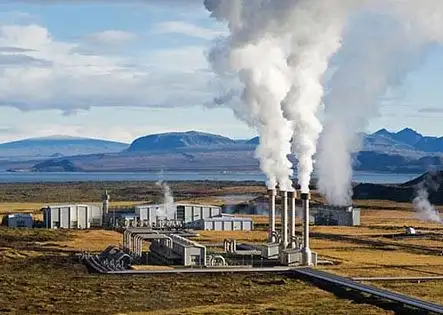
Geothermal Electricity is produced through geothermal power plants capturing the thermal energy contained in the Earth. Use of geothermal energy is based thermodynamically on the temperature difference between a mass of subsurface rock and water and a mass of water or air at the Earth's surface. This temperature difference allows production of thermal energy that can be either used directly or converted to mechanical or Geothermal Electricity. For context on broader methods and terminology, see this overview of electricity generation and how heat energy is converted to power.

Commercial exploration and development of Plant Geothermal water generated into Electricity to date have focused on natural geothermal reservoirs—volumes of rock at high temperatures (up to 662°F or 350°C) and with both high porosity (pore space, usually filled with water) and high permeability (ability to transmit fluid). The thermal energy is tapped by drilling wells into the reservoirs. The thermal energy in the rock is transferred by conduction to the fluid, which subsequently flows to the well and then to the Earth's surface where it can be converted into Geothermal Electricity. This well-to-turbine pathway is a fundamental part of electricity production from thermal resources.

There are several types of natural geothermal reservoirs. All the reservoirs developed to date for electrical energy are termed hydrothermal convection systems and are characterized by circulation of meteoric (surface) water to depth. The driving force of the convection systems is gravity, effective because of the density difference between cold, downward-moving, recharge water and heated, upward-moving, thermal water. A hydrothermal convection system can be driven either by an underlying young igneous intrusion or by merely deep circulation of water along faults and fractures. Depending on the physical state of the pore fluid, there are two kinds of hydrothermal convection systems: liquid-dominated, in which all the pores and fractures are filled with liquid water that exists at temperatures well above boiling at atmospheric pressure, owing to the pressure of overlying water; and vapor-dominated, in which the larger pores and fractures are filled with steam. Liquid-dominated reservoirs produce either water or a mixture of water and steam, whereas vapor-dominated reservoirs produce only steam, in most cases superheated. Because water acts as the primary working fluid in most systems, understanding the interplay of water and electricity helps clarify operational safety and design.

These hydrothermal systems are distinct from hydroelectricity produced by river impoundments, even though both ultimately rely on water as a medium.

Although geothermal energy is present everywhere beneath the Earth's surface, its use is possible only when certain conditions are met: (1) The energy must be accessible to drilling, usually at depths of less than 2 mi (3 km) but possibly at depths of 4mi (6–7km) in particularly favorable environments (such as in the northern Gulf of Mexico Basin of the United States). (2) Pending demonstration of the technology and economics for fracturing and producing energy from rock of low permeability, the reservoir porosity and permeability must be sufficiently high to allow production of large quantities of thermal water. (3) Since a major cost in geothermal development is drilling and since costs per meter increase with increasing depth, the shallower the concentration of geothermal energy the better. (4) Geothermal fluids can be transported economically by pipeline on the Earth's surface only a few tens of kilometers, and thus any generating or direct-use facility must be located at or near the geothermal anomaly. When these conditions align, engineered systems can efficiently generate electricity from accessible geothermal gradients.

The use of geothermal energy for Geothermal Electricity has become widespread because of several factors. Countries where geothermal resources are prevalent have desired to develop their own resources in contrast to importing fuel for power generation. In countries where many resource alternatives are available for power generation, including geothermal, geothermal has been a preferred resource because it cannot be transported for sale, and the use of geothermal energy enables fossil fuels to be used for higher and better purposes than power generation. Also, geothermal steam has become an attractive power generation alternative because of environmental benefits and because the unit sizes are small (normally less than 100 MW). Moreover, geothermal plants can be built much more rapidly than plants using fossil fuel and nuclear resources, which, for economic purposes, have to be very large in size. Electrical utility systems are also more reliable if their power sources are not concentrated in a small number of large units. In energy planning, geothermal is often evaluated alongside other forms of alternative electricity to balance portfolios and grid resilience. Many developers also highlight its contribution to green electricity targets thanks to low lifecycle emissions.

Related News

Ohm's Law Formula

The Ohm's Law formula is a cornerstone of electrical engineering, serving as a basis for analyzing and designing electric circuits. Its applications range from determining the appropriate values of electrical components to predicting the behaviour of complex systems. By exploring the relationship between voltage, current, and resistance and their connections with other fundamental laws in electromagnetism, we can gain a deeper understanding of the principles that govern the flow of electricity and its conversion into other forms of energy.

Ohm's Law states that the relationship between voltage, current, and resistance. This law, named after its discoverer Georg Simon Ohm, has wide-ranging applications in various fields, from the design of simple electrical circuits to complex electronic systems.

Ohm's Law, denoted as V=IR, dictates that the voltage (V) across a conductor between two points is directly proportional to the current (I) flowing through it, as long as the resistance (R) of the material remains constant. This equation lays the foundation for understanding electric circuits, and its relevance extends to both alternating current (AC) and direct current (DC) systems.

Let's consider a simple scenario to implement Ohm's Law. In an electrical circuit, a battery supplies voltage (also called electric potential or electromotive force), which causes electrons to flow, generating an electric current. The flow of these electrons encounters resistance due to the physical properties of the materials used in the circuit. The higher the resistance, the more the material opposes the flow of electrons, leading to a decrease in the electric current.

A practical application of Ohm's Law calculator can be found in determining a resistor's suitable value for a circuit. Using the formula V=IR, you can calculate the required resistance by rearranging the equation as R=V/I, where you substitute the known voltage and current values to find the unknown resistance.

When it comes to units, voltage is measured in volts (V), current in amperes (A), and resistance in ohms (Ω). It is essential to be mindful of these units when working with electrical components, as they determine the overall performance and safety of the system.

While Ohm's Law plays a critical role in understanding electric circuits, it is also interconnected with the concept of conductivity. Conductivity, a measure of a material's ability to conduct electrical energy, is the reciprocal of resistance. The more conductive a material is, the less resistance it exhibits, and vice versa. Conductivity helps engineers and designers select the right materials for specific applications, ensuring the efficiency and reliability of electrical systems.

However, Ohm's Law has its limitations. In real-world scenarios, resistance may not remain constant for all materials and under all conditions. Factors such as temperature, pressure, and the material's non-linear behaviour can cause deviations from the ideal behaviour predicted by Ohm's Law. As a result, this law is considered an ideal approximation for most practical purposes but may not be universally applicable.

Ohm's Law is also related to other fundamental laws in electromagnetism, such as Faraday's, Lenz's, and Biot-Savart's law. Faraday's Law describes the induction of voltage in a conductor moving through a magnetic field, while Lenz's Law explains the direction of the induced current due to this magnetic field. The Biot-Savart Law, on the other hand, calculates the magnetic field generated by an electric current. Understanding these laws is vital for grasping more complex concepts and phenomena in electromagnetism and their practical applications.


How to use Ohm's Law Equation

Let's consider an example of how to use Ohm's Law in a practical situation.

Suppose you have a 12-volt (V) battery connected to a simple electrical circuit with a single resistor. The current flowing through the resistor is measured to be 2 amperes (A). You can use Ohm's Law to calculate the resistance of the resistor in the circuit.

Recall the Ohm's Law formula: V = IR, where V is voltage, I is current, and R is resistance.

In this example, we know the voltage (V = 12 V) and the current (I = 2 A), and we want to find the resistance (R).

Rearrange the formula to solve for resistance: R = V / I

Now, substitute the known values into the formula:

R = 12 V / 2 A

R = 6 ohms (Ω)

So, the resistance of the resistor in this circuit is 6 ohms. By using Ohm's Law, you can determine unknown values in a circuit, such as resistance, as long as you have the other two known values (voltage and current).

View more

Electricity Terms Explained

Electricity terms explain voltage, current, resistance, impedance, power factor, frequency, AC/DC, circuits, transformers, and load. Master key definitions to analyze systems, size conductors, mitigate harmonics, and ensure safety compliance.


What Are Electricity Terms?

Standardized definitions for voltage, current, resistance, impedance, and power factor used in electrical engineering.

✅ Define units, symbols, and formulas per IEEE/IEC standards

✅ Clarify AC/DC behavior, phasors, impedance, and power factor

✅ Aid circuit analysis, sizing conductors, and safety compliance


Here are the top 50 commonly used electricity terms that are essential for understanding electrical systems, devices, and concepts: For a broader glossary with context and examples, see the curated list at Electrical Terms by Electricity Forum for deeper reference.

Voltage (V) – The electrical potential difference between two points in a circuit. Understanding how potential difference relates to the nature of electricity is clarified in this overview of what electricity is and how it behaves.

Current (I) – The flow of electric charge, measured in amperes (A). A concise explanation of electricity as a physical phenomenon is given in this definition of electricity for foundational understanding.

Resistance (R) – Opposition to current flow, measured in ohms (Ω).

Power (P) – The rate of doing work or transferring energy, measured in watts (W).

Ohm's Law – The relationship between voltage, current, and resistance. For a step-by-step refresher on the relationships among voltage, current, and resistance, explore this basic electricity guide to connect theory with practical examples.

Alternating Current (AC) – Electric current that reverses direction periodically.

Direct Current (DC) – Electric current that flows in one direction only. For a side-by-side comparison of waveform behavior, applications, and conversion methods, review the differences between AC and DC to strengthen conceptual understanding.

Frequency (f) – The number of cycles per second in AC, measured in hertz (Hz).

Impedance (Z) – The total opposition to current flow in an AC circuit, combining resistance and reactance, measured in ohms.

Capacitance (C) – The ability to store electrical energy in an electric field, measured in farads (F).

Inductance (L) – The ability of a conductor to induce a voltage when current changes, measured in henries (H).

Power Factor (PF) – The ratio of real power to apparent power, indicating the efficiency of a system.

Real Power (P) – The actual power consumed to perform work, measured in watts.

Apparent Power (S) – The total power in a system, combining real and reactive power, measured in volt-amperes (VA).

Reactive Power (Q) – Power in AC circuits that does not perform useful work, measured in volt-amperes reactive (VAR).

Load – The device or equipment that consumes electrical power.

Short Circuit – An abnormal connection between two points in a circuit, causing excessive current flow. To ground this topic in fundamentals, revisit what an electrical circuit is before examining fault conditions.

Overload – A condition where a circuit or device exceeds its rated current capacity.

Circuit Breaker – A protective device that interrupts the flow of current when an overload or short circuit occurs.

Fuse – A protective device that melts to break the circuit when excessive current flows.

Grounding (Earthing) – Connecting parts of an electrical system to the Earth to ensure safety.

Transformer – A device that transfers electrical energy between two or more circuits through electromagnetic induction.

Conductor – A material that allows the flow of electrical current, typically copper or aluminum.

Insulator – A material that resists the flow of electric current, such as rubber or plastic.

Phase – The distribution of alternating current electricity into separate waveforms, often used in three-phase power systems.

Watt (W) – The unit of power, equivalent to one joule per second.

Kilowatt (kW) – A unit of power equal to 1,000 watts.

Megawatt (MW) – A unit of power equal to 1 million watts.

Voltage Drop – The reduction in voltage across a component or conductor in an electrical circuit.

Arc Flash – A dangerous condition associated with the release of energy caused by an electric arc.

Resistor – A component that opposes the flow of current, used to control voltage and current in circuits.

Diode – A semiconductor device that allows current to flow in one direction only.

Rectifier – A device that converts AC to DC.

Inverter – A device that converts DC to AC.

Contactor – An electrically controlled switch used to control a power circuit.

Relay – A switch operated by an electromagnet, used for controlling circuits.

Switchgear – Equipment used to switch, control, and protect electrical circuits.

Distribution System – The system of wires and equipment that delivers electricity from substations to consumers.

Neutral – A conductor that carries current back to the source in an electrical system.

Busbar – A conductor used to distribute power from one source to multiple circuits.

Overcurrent Protection – Devices like fuses and circuit breakers designed to protect circuits from excessive current.

Phase Angle – The angular displacement between voltage and current waveforms in AC circuits.

Power Supply – A device that provides the necessary electrical power to a circuit or device.

Generator – A device that converts mechanical energy into electrical energy. This ties directly to how electrical energy is produced, transferred, and ultimately consumed.

Motor – A device that converts electrical energy into mechanical energy.

Frequency Converter – A device that changes the frequency of AC power.

Power Grid – A network of transmission lines, substations, and power stations for distributing electricity.

Service Panel – The central distribution point for electrical circuits in a building, containing circuit breakers or fuses.

Utility Transformer – A transformer that steps down high voltage for distribution to consumers.

Harmonics – Distortions in the electrical waveform that can affect power quality.

These terms cover a wide range of concepts from basic electrical theory to components and safety practices in electrical systems.


Related Articles

View more

Voltage Drop Formula

The voltage drop formula is V = I × R, where V represents the voltage drop, I represents the current in amperes, and R represents the resistance in ohms. It calculates the amount of voltage lost through a conductor and is essential for designing safe and efficient electrical systems.


What is Voltage Drop Formula?

A voltage drop formula can help you manually calculate the voltage drop in cables under full load in branch circuits. It does not matter if you are working with copper or aluminum conductors. To accurately calculate the voltage drop for a given cable size, length, and current, you need to know the resistance of the type of cable you’re using. 

✅ V = I × R for DC circuits

✅ Accounts for impedance in AC circuits

✅ Helps ensure safe, efficient electrical design

Use our voltage drop calculator to quickly determine wire size, conductor efficiency, and line loss for safer, more reliable electrical installations.


Power Quality Analysis Training

Power Factor Training

Request a Free Power Quality Training Quotation

To determine voltage drop in an electrical system, engineers and electricians use a standard formula that accounts for conductor resistance, current, and circuit length. The National Electrical Code (NEC) provides guidelines for the maximum voltage drop allowed in various installations to ensure efficiency and safety. For both single-phase and three-phase circuits, excessive voltage drop can lead to poor equipment performance and energy loss. To simplify calculations, a voltage drop calculator can quickly assess whether a circuit meets NEC recommendations and optimize conductor sizing accordingly. You can learn more about how electrical resistance affects circuits in our detailed voltage drop guide, which explains causes, calculations, and solutions for safe, efficient power distribution.


DC / single phase calculation

The voltage drop V in volts (V) is equal to the wire current I in amps (A) times 2 times one way wire size length L in feet (ft) times the wire resistance per 1000 feet R in ohms (Ω/kft) divided by 1000:


Vdrop (V) = Iwire (A) × Rwire(Ω)

Iwire (A) × (2 × L(ft) × Rwire(Ω/kft) / 1000(ft/kft))


The voltage drop V in volts (V) is equal to the wire current I in amps (A) times 2 times one way wire length L in meters (m) times the wire resistance per 1000 meters R in ohms (Ω/km) divided by 1000:


Vdrop (V) = Iwire (A) × Rwire(Ω)

Iwire (A) × (2 × L(m) × Rwire (Ω/km) / 1000(m/km))


3 phase calculation

The line-to-line voltage drop V in volts (V) is equal to the square root of 3 times the wire current I in amps (A) times one-way wire length L in feet (ft) times the wire resistance per 1000 feet R in ohms (Ω/kft) divided by 1000:


Vdrop (V) = √3 × Iwire (A) × Rwire (Ω)

= 1.732 × Iwire (A) × (L(ft) × Rwire (Ω/kft) / 1000(ft/kft))


The line-to-line voltage drop V in volts (V) is equal to the square root of 3 times the wire current I in amps (A) times one-way wire length L in meters (m) times the wire resistance per 1000 meters R in ohms (Ω/km) divided by 1000:


Vdrop (V) = √3 × Iwire (A) × Rwire (Ω)

= 1.732 × Iwire (A) × (L(m) × Rwire (Ω/km) / 1000(m/km))


Wire diameter calculations

The n gauge wire diameter, dn in inches (in), is equal to 0.005in times 92 raised to the power of 36 minus gauge number n, divided by 39:


dn (in) = 0.005 in × 92(36-n)/39


The n gauge wire diameter dn in millimetres (mm) is equal to 0.127mm times 92 raised to the power of 36 minus gauge number n, divided by 39:


dn (mm) = 0.127 mm × 92(36-n)/39


Wire cross-sectional area calculations

The n gauge wire's cross-sectional area An in kilo-circular mils (kcmil) is equal to 1000 times the square wire diameter d in inches (in):


An (kcmil) = 1000×dn2 = 0.025 in2 × 92(36-n)/19.5


The n gauge wire's cross-sectional area An in square inches (in2), is equal to pi divided by 4 times the square wire diameter d in inches (in):


An (in2) = (π/4)×dn2 = 0.000019635 in2 × 92(36-n)/19.5


The n gauge wire's cross-sectional area, An, in square millimetres (mm2), is equal to pi divided by 4 times the square wire diameter d in millimetres (mm):


An (mm2) = (π/4)×dn2 = 0.012668 mm2 × 92(36-n)/19.5


Wire resistance calculations

The n gauge wire resistance R in ohms per kilofeet (Ω/kft) is equal to 0.3048×1000000000 times the wire's resistivity ρ in ohm-meters (Ω·m) divided by 25.42 times the cross-sectional area An in square inches (in2):


R(Ω/kft) = 0.3048 × 10⁹ × ρ(Ω·m) / (25.42 × An (in2))


The n gauge wire resistance R in ohms per kilometre (Ω/km) is equal to 1000000000 times the wire's resistivity ρ in ohm-meters (Ω·m) divided by the cross-sectional area An in square millimetres (mm2):


R(Ω/km) = 109 × ρ(Ω·m) / An (mm2)


Related Pages


View more

What is Open Circuit Voltage? Explained

Open circuit voltage is the potential difference measured across the terminals of a device when no external load is applied. Common in batteries, solar cells, and electrical circuits, it helps evaluate performance, efficiency, and voltage characteristics.


What is Open Circuit Voltage?

It is the maximum voltage measured across terminals when no current flows in the circuit, providing a baseline for performance evaluation.

✅ Indicates battery and solar cell efficiency

✅ Helps assess electrical circuit performance

✅ Defines voltage without current flow

What is open circuit voltage? Often abbreviated as OCV, is an essential concept within electrical engineering, particularly relevant to professionals handling electrical systems or devices. Defined as the electrical potential difference between two points in a circuit when no current flows, OCV represents the maximum voltage achievable without applying a load. For electrical workers, understanding OCV is crucial, as it enables the evaluation of power sources and the identification of potential issues within a circuit before engaging with it under load. Knowledge of OCV benefits electrical workers by providing insights into system readiness, ensuring operational safety, and facilitating troubleshooting for optimal equipment performance. Understanding basic electricity is the foundation for grasping what open circuit voltage means, since it defines how voltage behaves when no current flows.


Determining Open Circuit Voltage

OCV can be measured using instruments like digital multimeters, which provide readings of the maximum electrical potential in the circuit. When conducting a test, it’s essential to measure the resistance between two terminals with no current flow. For instance, if a circuit is connected to a 12-volt battery with no load, the multimeter will display the OCV, which typically matches the battery’s maximum voltage. Similarly, in a solar cell, the OCV provides an indication of the maximum power it can generate when fully charged. Such measurements are helpful in evaluating the state of charge and operational status, providing valuable data to maintain system health. A solid grasp of electrical resistance is also critical, as resistance affects how potential differences are measured when a circuit is open.


Open Circuit Voltage Test

The open-circuit voltage test, also known as the no-load test, is a standard procedure in electrical engineering for assessing a power source's condition when it is not under load. In this test, an engineer connects a voltmeter to the terminals of a circuit to measure the OCV. This process is valuable for detecting issues such as short circuits, high resistance, or compromised wiring, which can lead to performance problems. The results from this test enable electrical professionals to detect weak points in a circuit before it operates under load, ensuring smoother and safer functionality. Open-circuit voltage is directly related to capacitance, as capacitors store electrical potential that can be measured under no-load conditions.


Applications of Open Circuit Voltage 

In practical applications, open circuit voltage is not just a measurement but a vital diagnostic tool. For example, in renewable energy systems, engineers often assess solar cell efficiency by examining its OCV. A solar cell’s OCV indicates its potential output, enabling accurate calculations of energy capacity and state of charge. Understanding OCV also aids in selecting voltage levels appropriate for different components, especially in high-voltage systems where matching component capacity is essential. In this way, OCV serves as a baseline for electrical potential, enabling engineers to optimize systems for both performance and safety. Engineers often compare OCV with direct current behavior, where stable voltages are easier to measure without the influence of alternating loads.

The concept of OCV has safety implications. By knowing the maximum potential voltage in a circuit before activating it, engineers can implement safeguards to avoid overloads or shorts that might occur under load. In electrical troubleshooting, measuring OCV allows for the identification of circuits that aren’t performing optimally, pinpointing faults or abnormal resistance that could lead to hazards. Hence, for electrical workers, mastering OCV measurement is not only about system performance but also about adhering to safety standards that protect both personnel and equipment.


Frequently Asked Questions


What is Open Circuit Voltage?

Open circuit voltage refers to the electrical potential, or maximum voltage, present between two conductors in a circuit when there is no active current flowing. This concept is applicable to both direct current (DC) and alternating current (AC) circuits. In DC systems, the OCV remains stable at a maximum level when no load is connected. In AC circuits, OCV may vary depending on factors such as load fluctuations and circuit design. The measurement of OCV is crucial for determining the performance of various devices, including solar cells, where the state of charge can be observed by checking the OCV. Electrical engineers and technicians can use this information to diagnose issues and assess the readiness of systems for operation. In 3-phase electricity systems, knowing the open circuit voltage helps engineers ensure balance and reliability before load conditions are applied.


Why Open Circuit Voltage Matters

For anyone working in electrical engineering, understanding open-circuit voltage is essential for designing and troubleshooting systems. OCV indicates the maximum voltage a circuit can sustain, helping engineers select compatible components and design for peak efficiency. For instance, when assessing a solar cell, the OCV helps identify the electrical potential it can generate without applying any load. In this way, OCV is a guide to the expected performance under load-free conditions, ensuring that devices will perform within specified limits when placed in actual operation. The concept also closely relates to active power, as OCV provides a baseline for calculating the amount of real power a system can deliver once current begins to flow.


Does open circuit voltage change with temperature?

Yes, temperature can affect open circuit voltage. For example, solar cells typically show a decrease in OCV as temperature rises, which impacts efficiency and energy output.


Is the open circuit voltage always equal to the source voltage?

Not always. While OCV often matches the nominal source voltage, internal resistance, aging, or chemical changes in a battery can cause the measured value to differ slightly.


Can open circuit voltage predict battery health?

OCV can give an indication of a battery’s state of charge, but it is not a complete measure of health. Additional tests, such as load testing, are needed to assess the overall condition.


How does open circuit voltage relate to safety testing?

Measuring OCV before energizing equipment enables engineers to confirm expected voltage levels and prevent hazardous conditions that may arise under load.


Is open circuit voltage used in AC systems as well as DC?

Yes, OCV applies to both AC and DC systems. In AC circuits, variations may occur depending on the design and frequency, whereas DC systems typically provide a stable maximum value.


What is open circuit voltage? Open circuit voltage is more than just a technical measurement; it is a vital reference point for understanding the behavior of batteries, solar cells, and electrical circuits under no-load conditions. By measuring OCV, electrical professionals gain valuable insights into efficiency, reliability, and safety before current flows, ensuring systems are prepared for real-world operation. Whether applied in renewable energy, troubleshooting, or equipment testing, open circuit voltage provides the foundation for sound engineering decisions and safer electrical practices.


Related Articles


View more

Wireless Electricity

Wireless electricity transmits power without wires using electromagnetic fields, such as magnetic resonance or microwave transmission. It enables charging devices remotely, powering sensors, and improving efficiency in smart grids, EVs, and wireless charging systems.


What is Wireless Electricity?

Wireless electricity refers to the transmission of electrical energy without physical conductors like wires.

✅ Powers devices through electromagnetic fields, like inductive coupling

✅ Enables contactless charging in consumer electronics and EVs

✅ Supports smart grids, IoT, and remote sensors with flexible energy delivery

Wireless electricity, also known as wireless power transmission, was first conceptualized by Nikola Tesla, a pioneer in the field of alternating current (AC) electricity. Tesla’s groundbreaking experiments at Colorado Springs in 1899 showcased how power could be transmitted without wires using a magnetic field. He used a Tesla coil to transmit 100 million volts of high power over a distance of 26 miles, wirelessly powering 200 light bulbs and an electric motor. His vision was to develop a wireless system capable of transmitting power over long distances with minimal energy loss.

Tesla’s system relied on a high-frequency alternating current and magnetic resonance to transmit power wirelessly. His experiments with the Tesla coil laid the groundwork for modern wireless technologies, including short-range wi

reless power transmission systems, such as wireless charging pads and Wi-Fi routers. Wireless charging pads today utilize magnetic fields to transmit power to devices, a concept similar to Tesla’s idea of harnessing the Earth’s resonance to transmit power over longer distances. Tesla’s vision extended beyond short-range wireless systems—he dreamed of a global system where energy flows freely through the air without requiring a direct line of sight.

Tesla’s experiments also demonstrated the efficiency of wireless systems. The Tesla coil could transmit power wirelessly to fluorescent light bulbs even when they were several feet away from the coil. This concept of powering devices wirelessly has evolved over time, with companies like Wi-Charge developing systems to transmit power wirelessly to small devices. In Tesla’s time, he envisioned a world where any amount of power could be transmitted wirelessly across the globe. However, financial struggles eventually led to the abandonment of his wireless power transmission projects, including the unfinished Wardenclyffe tower on Long Island. Devices powered wirelessly still rely on efficient energy flow, making concepts such as electrical resistance and impedance crucial to design and performance.

Despite Tesla’s challenges, modern advancements have kept his vision alive. Short-range wireless power transmission systems, like those used in Wi-Fi routers and wireless charging pads, are now commonplace. These technologies utilize magnetic fields to transmit power wirelessly over short distances, offering a practical solution for wirelessly charging devices such as smartphones and laptops. Wi-Charge is exploring the potential of wirelessly charging devices without requiring close contact, enabling more flexible and efficient energy distribution. Tesla’s coil and modern systems like Wi-Charge operate based on resonant principles, closely related to inductance and capacitance.


Modern Innovations in Wireless Electricity

Recent breakthroughs have brought Tesla’s dream closer to reality:

  • In 2024, DARPA successfully transmitted 800 watts of power over 5 miles using a laser beam—enough to make popcorn at the receiver site.

  • KAIST in South Korea demonstrated the ability to charge 40 smartphones at once using magnetic resonance over a distance of 5 meters.

  • Detroit’s Corktown district now hosts a functioning inductive charging roadway, allowing EVs to charge wirelessly while in motion.

These examples show that wireless electricity is no longer a distant vision but a rapidly advancing technology with real-world applications. Concepts such as watts, volts, and amperes remain fundamental even in advanced wireless systems.


Types of Wireless Power Transmission Technologies

Technology Type Description and Use Cases
Inductive Coupling Short-range charging pads for phones, laptops, and wearables
Magnetic Resonance Mid-range charging for larger devices and multiple receivers simultaneously
Microwave Transmission Long-range point-to-point energy transfer; used in research and satellites
Laser Power Beaming High-efficiency focused beams for distant targets; demonstrated by DARPA
Infrared Light (Wi-Charge) Contactless charging for smart locks and IoT devices


Applications of Wireless Electricity

  • Consumer Electronics: Wireless charging pads and smart home devices are now common.

  • Electric Vehicles (EVs): Inductive charging roads and parking pads reduce dependency on cable stations.

  • Medical Implants: Enables powering of implants and biosensors without invasive wiring.

  • Remote Sensors: In agriculture, factories, and infrastructure, wireless power extends sensor life.

  • Smart Grids: Flexible energy distribution for remote locations and emergency response.


Challenges and Future Outlook

Despite its promise, wireless electricity faces challenges:

  • Efficiency drops over distance

  • Alignment issues in inductive systems

  • Line-of-sight limitations in laser and IR systems

  • Safety regulations for high-power beaming

However, the future is promising. Emerging materials, such as metamaterials and metasurfaces, are enhancing transmission efficiency. AI-enhanced beam control, dynamic alignment systems, and frequency-agnostic receivers are under development.

From Tesla's early experiments to DARPA's record-setting laser transmission, wireless electricity is evolving into a transformative force. As the technology matures, its applications will expand, powering a world that may one day be truly wire-free.


Related Articles


View more

Water Electricity

Water electricity refers to electrical power generated using water, primarily through hydroelectric systems. It converts the kinetic energy of moving or falling water into electricity, providing a renewable and sustainable energy source with low carbon emissions and high efficiency.


What is: “Water Electricity?”

Water electricity, also known as hydroelectric power, is energy derived from moving water. It’s a leading source of renewable electricity worldwide.

✅ Converts water’s kinetic energy into usable electricity

✅ Offers renewable, low-emission electricity generation

✅ Used in dams, rivers, and tidal energy systems

 Most hydroelectric power is generated from the potential energy of dammed water, which drives a water turbine and generator. Less common variations utilize water's kinetic energy or undammed sources, such as tidal power. Hydroelectricity is a renewable energy source.

The energy extracted from water depends not only on the volume but on the difference in height between the source and the water's outflow. This height difference is referred to as the head. The amount of potential energy in water is directly proportional to the head. To obtain a very high head of water for a hydraulic turbine, water may be run through a large pipe called a penstock.

While many supply public power networks, some Water Electricity projects were created for private commercial purposes. For example, aluminum processing requires substantial amounts of power, and in Britain's Scottish Highlands, there are examples at Kinlochleven and Lochaber, designed and constructed during the early 20th century. Similarly, the 'van Blommestein' lake, dam and power station were constructed in Suriname to provide power for the Alcoa aluminum industry. In many parts of Canada (specifically, the provinces of British Columbia, Manitoba, Ontario, Quebec, and Newfoundland and Labrador), hydroelectricity is used so extensively that the word "hydro" is often used to refer to any power delivered by a power utility. The government-run power utilities in these provinces are called BC Hydro, Manitoba Hydro, Hydro One (formerly "Ontario Hydro"), Hydro-Québec and Newfoundland and Labrador Hydro, respectively. Hydro-Québec is the world's largest hydroelectric generating company, with a total installed capacity (2005) of 31,512 MW. For deeper insight into how to generate electricity from various sources, including water, visit our guide on hydroelectricity, which explains methods, systems, and real-world examples.


Importance

Water and Electricity power supplies 20% of the world's electricity. Norway produces virtually all of its energy from hydroelectric sources. In contrast, Iceland produces 83% of its requirements (as of 2004), and Austria generates 67% of all power in the country from hydroelectric sources (over 70% of its total requirements). Canada is the world's largest producer of Water Electricity, and produces over 70% of its electric power from hydroelectric sources.

Apart from a few countries with an abundance of it, hydro capacity is normally applied to peak-load demand, because it can be readily stored during off-peak hours (in fact, pumped-storage hydroelectric reservoirs are sometimes used to store power produced by thermal plants for use during peak hours). It is not a major option for the future in developed countries because most major sites in these countries that have the potential for harnessing gravity in this way are either already being exploited or are unavailable for other reasons, such as environmental considerations.

Regions where thermal plants provide the dominant supply of power utilize Water Electricity to provide the important functions of load following and regulation. This permits thermal plants to be operated closer to thermodynamically optimal points rather than varied continuously, which reduces efficiency and potentially increases pollutant emissions. Concurrently, hydro plants are then utilized to provide for hour-to-hour adjustments and to respond to changes in system frequency and voltage (regulation), with no additional economic or environmental effect.


Related Articles


View more

Sign Up for Electricity Forum’s Newsletter

Stay informed with our FREE Newsletter — get the latest news, breakthrough technologies, and expert insights, delivered straight to your inbox.

Electricity Today T&D Magazine Subscribe for FREE

Stay informed with the latest T&D policies and technologies.
  • Timely insights from industry experts
  • Practical solutions T&D engineers
  • Free access to every issue

Live Online & In-person Group Training

Advantages To Instructor-Led Training – Instructor-Led Course, Customized Training, Multiple Locations, Economical, CEU Credits, Course Discounts.

Request For Quotation

Whether you would prefer Live Online or In-Person instruction, our electrical training courses can be tailored to meet your company's specific requirements and delivered to your employees in one location or at various locations.