What Is Alternating Current?
By R.W. Hurst, Editor
Alternating current is an electric current that reverses direction at a set frequency, usually 50 or 60 hertz. AC powers homes, industries, motors, lighting, and grids because it can be transmitted over long distances.
What is Alternating Current?
Alternating current, commonly referred to as AC, is a form of electrical current in which the direction of charge flow reverses at regular intervals. Unlike direct current, which moves in one constant direction, AC oscillates back and forth. This change in direction allows AC to be generated efficiently, transmitted over long distances, and adapted to a wide range of voltage levels.
AC electricity is the standard form of electricity used in homes, commercial buildings, and industrial facilities worldwide. Its ability to work seamlessly with transformers makes it the foundation of modern power grids.
Understanding How Alternating Current Works
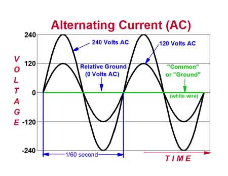
In an alternating current system, electrons do not travel continuously from the power plant to the device. Instead, they vibrate back and forth within the conductor as the voltage polarity changes. This oscillation creates a repeating electrical waveform, most commonly a sine wave.
The frequency of this waveform determines how often the current reverses direction. In North America, AC electricity operates at 60 hertz, meaning the current changes direction 60 times per second. In much of Europe, Asia, and Africa, the standard frequency is 50 hertz.
In most North American power systems, electricity is delivered at 60 hz using alternating current ac, a format that allows electrical energy to be generated efficiently and transmitted over long distances. This type of current is especially well-suited for operating electric motors, which rely on changing magnetic fields to produce smooth, continuous motion. At the core of this process is the principle of electromagnetic induction, where a moving magnetic field induces a voltage in a conductor, converting mechanical motion into usable electrical energy and back again inside generators and motors.
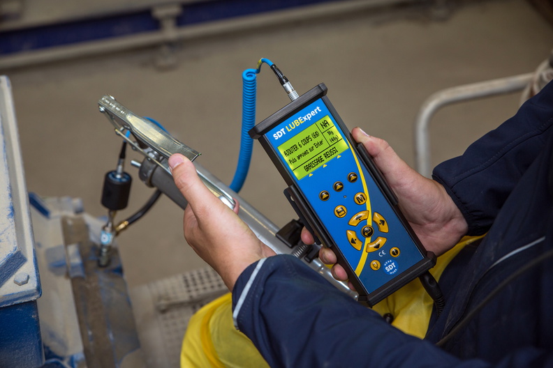
A multimeter is commonly used to measure AC electricity voltage and current in residential and industrial electrical systems.
AC vs. DC: Basic Differences
The difference between alternating current and direct current lies in how electrical charge moves through a circuit. Direct current flows steadily in one direction and is commonly produced by batteries, solar panels, and electronic power supplies. AC electricity, by contrast, continuously changes direction.
This difference has practical consequences. DC is well-suited for electronics and energy storage, while alternating current is far more practical for distributing electricity across cities and regions. The ability to raise and lower AC voltage efficiently gives it a major advantage in large-scale power systems. The contrast between AC and DC becomes clearer when comparing alternating current to direct current, which flows in only one direction and is commonly used in batteries and electronic devices.
Devices like the voltmeter are specifically designed to measure AC or DC voltage, helping technicians verify circuit functionality and safety.
Why Alternating Current Is Used for Power Transmission
One of the primary reasons AC electricity dominates electrical transmission is its ability to transform voltages. Using transformers, alternating current voltage can be increased to very high levels for transmission, reducing current and minimizing energy loss along power lines. Near the point of use, the voltage can then be reduced to safe levels for homes and equipment.
This flexibility allows electricity to travel hundreds of kilometres with relatively low losses, something that would be far more complex using direct current alone. In modern power systems, alternating current is closely tied to how the electricity grid operates, allowing voltage to be stepped up for transmission and stepped down again for safe use.
In contrast, DC power cannot be easily adjusted, making it less suitable for long-distance power transmission.
How Alternating Current Is Generated
AC electricity is produced through electromagnetic induction. In generators and alternators, a magnetic field interacts with a rotating conductor, or a rotating magnetic field interacts with stationary conductors. As the rotation continues, the induced voltage changes polarity, naturally creating an alternating current.
This principle applies across power generation methods, including hydroelectric, thermal, nuclear, and wind generation. Regardless of the energy source, the electrical output supplied to the grid is alternating current. Large industrial facilities often rely on three phase electricity because it delivers smoother power and supports heavy motors more efficiently than single-phase systems.
Frequency and Its Importance
Alternating current frequency affects how electrical devices operate. Motors, clocks, and timing circuits are designed to match the frequency of the power supply. A motor connected to the wrong frequency may run at an incorrect speed or overheat.
This is why electrical equipment is often rated for either 50 hertz or 60 hertz operation, and why frequency control is a critical part of grid stability. The ability to transform voltage levels depends on electromagnetic principles explained by Faraday’s law of induction, which underpins generators and transformers alike.
The Role of Transformers in Alternating Current Systems
Transformers are essential to alternating current systems. They work by transferring energy between coils through a changing magnetic field. By adjusting the number of turns in each coil, transformers can increase or decrease voltage without changing frequency. Components such as coils and motors in alternating current systems are influenced by inductance, which affects how current responds to changing magnetic fields.

This simple but powerful principle enables efficient transmission, safe distribution, and proper operation of electrical devices across a wide range of applications. Understanding alternating current behavior also requires familiarity with impedance, since resistance, inductance, and capacitance all influence current flow in alternating circuits.
Advantages of Alternating Current
Alternating current offers several practical benefits:
-
Voltage can be easily stepped up or down
-
Long-distance transmission is efficient
-
Large motors operate reliably on alternating current
-
Power generation integrates naturally with alternating current grids
Because of these advantages, AC remains the backbone of global electrical infrastructure.
Alternating Current in Everyday Life
From lighting and heating to motors and industrial machinery, alternating current supports nearly every aspect of modern life. Its compatibility with transformers, ease of generation, and adaptability across voltage levels make it indispensable to residential, commercial, and industrial power systems.
Understanding how alternating current works provides essential context for topics such as power quality, voltage regulation, electrical safety, and grid reliability.
To understand how voltage affects electrical circuits, it's essential to examine how voltage drop can cause energy loss, especially over long distances.
Related Articles
