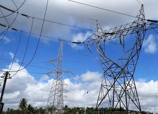
Sources of Electricity Explained


Sources of Electricity

Sources of electricity include fossil fuels, nuclear power, and renewable energy like solar, wind, and hydro. These energy sources provide reliable electricity generation, powering homes, industries, and grids while shaping modern energy systems and sustainability goals.


What are the Sources of Electricity?

Sources of electricity are the various energy systems used to generate electrical power, ranging from conventional fuels to renewable technologies.

✅ Include fossil fuels, nuclear power, and renewable energy

✅ Used in electricity generation across all sectors

✅ Impact cost, sustainability, and environmental footprint

In the modern world, electricity plays a crucial role in our daily lives. As a result, it has become an essential commodity, from powering our homes to running industries. But have you ever wondered where it comes from? Electric power can be generated from various sources with unique characteristics, benefits, and drawbacks. In this article, we'll delve into the main sources of electric power generation and discuss their environmental impacts, costs, and efficiency. Renewable sources, such as hydro, solar, and wind, contrast with alternative electricity options that aim to reduce dependence on fossil fuels.

The primary sources of electric power used to produce electric power can be broadly categorized into renewable and non-renewable resources. Renewable energy sources, such as solar, wind, hydroelectric, geothermal, and biomass, are replenished naturally and have a lower environmental impact than non-renewable sources. Non-renewable energy sources include fossil fuels such as coal, natural gas, and oil, as well as nuclear energy. These resources are finite, and their extraction and utilization contribute to environmental issues like air pollution and climate change. Hydroelectric dams, wind turbines, and solar farms all contribute to global electricity generation, reducing reliance on non-renewable sources.

According to the U.S. Energy Information Administration, global electricity production relies on a mix of renewable and non-renewable sources. While traditional thermal power plants, fueled by coal, natural gas, and nuclear energy, remain central to electricity generation, the rapid growth of solar photovoltaics is transforming how we create and consume electricity. Many nations are investing heavily in utility-scale electricity projects, from massive solar farms to offshore wind facilities, to meet rising demand while reducing emissions. These shifts illustrate how diverse technologies collectively shape the future of reliable and sustainable power.


Fossil Fuels: The Traditional Backbone

Fossil fuels remain the dominant source of electricity worldwide. In 2023, they accounted for roughly 61% of global power generation. In the U.S., about 60% of electric power still comes from coal, natural gas, and oil. These fuels are burned to produce heat, which converts water into steam that drives turbines to generate electric power.

While fossil fuels offer reliability and established infrastructure, they release large amounts of greenhouse gases, contributing significantly to air pollution and climate change.


Nuclear Energy: Low Carbon but Controversial

Nuclear energy provides approximately 9% of the world's electric power and nearly 19% in the United States. It works by splitting atoms (nuclear fission) to release energy that turns water into steam, which then drives turbines.

Nuclear power is highly efficient and emits no carbon during operation. However, it poses concerns regarding radioactive waste, high capital costs, and the potential for catastrophic failures.


Renewable Energy: The Fastest-Growing Sector

Renewable energy sources are expanding rapidly due to technological advances and falling costs. In 2023, they accounted for approximately 30% of global electric power, with wind and solar energy experiencing the fastest growth. Among renewables, Geothermal Electricity harnesses Earth’s internal heat to produce reliable baseload power even in regions with limited solar or wind potential.


Solar Power

Solar energy converts sunlight into electric power using photovoltaic cells, also known as photovoltaic panels. It's scalable, from rooftop systems to massive solar farms, and has seen significant cost reductions over the past decade.


Wind Power

Wind turbines capture kinetic energy from the wind to generate electric power. Wind farms are increasingly common in the U.S., Europe, and China. Like solar energy, wind energy is intermittent, but storage technology is continually improving.


Hydroelectric Power

Hydroelectricity uses flowing water to turn turbines. It's the most established renewable source and provides reliable base-load power. However, large dams can disrupt ecosystems and displace communities. Hydroelectricity stands out as a mature and stable form of renewable generation, as detailed on our Hydroelectricity page.


Geothermal and Biomass

Geothermal taps into Earth’s internal heat, while biomass burns organic material. While smaller in scale, both contribute to energy diversity and localized solutions. Geothermal power generation complements solar, wind, and hydroelectric sources by offering a steady, round-the-clock output, as explained in our detailed guide on Geothermal Electricity.


Comparing Sources of Electricity

Source Global Share (2023) U.S. Share (2023) Key Advantages Key Drawbacks
Fossil Fuels ~61% ~60% Reliable, established infrastructure High emissions, non-renewable
Nuclear ~9% ~19% Low carbon, high efficiency Radioactive waste, high cost
Renewables ~30% ~21% Clean, sustainable, fast-growing Intermittent, resource/location dependent


The diverse world of electric power choices offers a range of technologies that can help meet the growing global demand for energy. By understanding the characteristics, environmental impacts, costs, and efficiencies of these sources, we can make informed decisions about transitioning to cleaner, more sustainable energy systems. As renewable energy technologies continue to advance and energy storage solutions mature, the future of electric power generation is likely to be increasingly dominated by clean, sustainable sources that reduce our impact on the planet and provide reliable power for future generations.


Environmental Impact and Efficiency

The environmental effects of each source vary significantly:

  • Coal and oil are the dirtiest, producing the most CO2 and pollutants.

  • Natural gas emits less CO2 but still contributes to climate change.

  • Nuclear has a low operational footprint but long-term waste issues.

  • Solar and wind energy produce no emissions during use, although manufacturing has some environmental impact.


Efficiency also differs:

  • Natural gas plants can achieve thermal efficiencies exceeding 60%.

  • Nuclear reactors are highly efficient, but they are slow to build.

  • Coal is among the least efficient.

  • Renewables vary based on technology and location.


Cost Considerations

Costs are influenced by technology, fuel, geography, and infrastructure:

  • Solar and wind costs have dropped dramatically, making them competitive with fossil fuels.

  • Nuclear has high upfront costs but low operating costs.

  • Fossil fuels fluctuate in response to changes in market supply and demand.


Future Trends in Power Generation

The energy sector is moving toward decarbonization. Key trends include:

  • Growth in solar and wind capacity

  • Advances in energy storage systems

  • Development of smart grids and microgrids

  • Investment in fusion energy research

Many countries are setting net-zero goals, aiming for cleaner and more sustainable electricity systems.

Electric power can be generated from various sources, each with its trade-offs in terms of cost, efficiency, and environmental impact. While fossil fuels still dominate, the momentum is clearly shifting toward renewable energy sources. A diversified energy mix, supported by smart technologies and forward-looking policies, will power the sustainable future. To understand how energy sources are converted into power, refer to our 'Generate Electricity' article, which describes the entire process from fuel or resource to grid delivery.

Understanding the strengths and weaknesses of each source helps shape a more resilient, efficient, and eco-friendly power generation landscape. Whether from fossil fuels, nuclear, or renewables, every source of electricity must connect to the electricity grid to deliver power where it is needed.


Related Articles


Related News

3 PHASE ELECTRICITY

3 Phase Electricity supplies AC three-phase power via 120° phase-shifted sinusoidal waveforms, enabling balanced loads, higher power factor, efficient distribution, and smooth torque for industrial motors across commercial facilities and the electrical grid.


What Is 3 Phase Electricity?

An AC system with three sinusoidal phases delivering balanced, efficient power for distribution and industrial motors.

✅ Three 120° phase-shifted AC waveforms share balanced loads.

✅ Lower conductor size and losses than single-phase systems.

✅ Powers large motors with smoother torque and better efficiency.


3 phase electricity is referred to alternating current. It is best described as the timing of the electron movements. It is the most common delivery method worldwide because it is a cheaper and easier way to transmit power from one place to another. While this method of electrical transmission is popular in industrial, commercial and institutional power systems, most homes only use single-phase power. For a concise overview, see the three-phase electricity guide for context.


What does it mean?

If wires are in "phase", it means that timing of the electron movement, back and forth, is the same. The electrons are "in step" or "in time".

For newcomers, the basic electricity tutorial explains charge, current, and phase in simple terms.

To transmit and distribute alternating current, it is more efficient to use 3 circuits that are out of sequence. This idea was discovered by Nikola Tesla (1856 -1943). Much of its efficiency is because there is always voltage (electrons moving) in at least one wire.

You can review how alternating current behaves in circuits in the how electricity works resource to see why shifting phases improves continuity.

He found that it is an arrangement that fits in very nicely with generator design. The 120° phasing separation allows close to the optimum spacing and size of the copper conductors around the stator bore. The compatible generator is the cheapest form to make. Design notes for 3-phase power highlight how 120° spacing reduces copper and iron losses.

This type of power is designed especially for large electrical loads where the total electrical load is divided among the three separate phasing sequences. As a result, the wire and transformers will be less expensive than if these large loads were carried on a single system.

Generators usually have three separate windings, each producing its own separate single-phase voltage. Since these windings are staggered around the generator circumference, each of the voltages is "out of phase" with one another. That is, each of the three reaches the maximum and minimum points in the AC cycle at different times.

Definitions of "phase angle" and "phase sequence" are covered in the electricity terms glossary for reference.

Power is generated at electric utilities in this way. But, if this power is better than single phase, why not four, five or six phase? Theoretically, these would be even better, but equipment manufacturers would have to build motors to use it, and that just wouldn't be cost effective given the installed base of equipment that must continue to be powered. Utility practices for distribution are summarized in the electricity supply overview which also outlines standard voltage systems.

The word is often abbreviated using the Greek letter "phi" and is written as a zero with a slash mark through it.

The most important class of load is the electric motor. An induction motor has a simple design, inherently high starting torque, and high efficiency. Such motors are applied in industry for pumps, fans, blowers, compressors, conveyor drives, and many other kinds of motor-driven equipment. A motor will be more compact and less costly than a motor of the same voltage class and rating; and AC motors above 10 HP (7.5 kW) are uncommon. Three phase motors will also vibrate less and hence last longer than motor of the same power used under the same conditions.

Large air conditioning, etc. equipment use motors for reasons of efficiency, economy and longevity.

Resistance heating loads such as electric boilers or space heating may be connected to systems. Electric lighting may also be similarly connected. These types of loads do not require the revolving magnetic field characteristic of motors but take advantage of the higher voltage and power level usually associated with distribution. Fluorescent lighting systems also benefit from reduced flicker if adjacent fixtures are powered from different.

Large rectifier systems may have inputs; the resulting DC current is easier to filter (smooth) than the output of a rectifier. Such rectifiers may be used for battery charging, electrolysis processes such as aluminum production, or for operation of DC motors.

An interesting example of a load is the electric arc furnace used in steelmaking and in refining of ores.

In much of Europe stoves are designed to allow for a feed. Usually the individual heating units are connected between phase and neutral to allow for connection to a supply where this is all that is available.

For homeowners, the home electricity section explains single-phase panels, breakers, and typical loads.


Related Articles

View more

Capacitors in Series Explained

Capacitors in series lower the total capacitance but increase voltage handling. This configuration is widely used in electronics, circuit design, and energy storage to balance voltage and improve reliability.


What are Capacitors in Series?

Capacitors in series describe a circuit configuration where capacitors are connected end to end, affecting capacitance and voltage distribution.

✅ The total capacitance is always less than the smallest capacitor value

✅ Voltage divides across each capacitor based on its capacitance

✅ Improves voltage rating of circuits while lowering equivalent capacitance

They play a critical role in various electronic applications, and understanding their characteristics, advantages, and potential drawbacks is essential for designing and implementing successful circuits. By mastering the concepts of capacitance, voltage distribution, and energy storage, one can leverage capacitors in series to create optimal circuit designs. To fully understand how capacitors (caps) behave in different setups, it helps to compare Capacitance in Parallel with series connections and see how each affects circuit performance.


Capacitors are fundamental components in electronic circuits, and their applications are vast, ranging from simple timing circuits to sophisticated filtering applications. This article delves into the intricacies of caps connected in series, highlighting their characteristics, advantages, and potential drawbacks.

To understand capacitors in series, it's essential first to grasp the concept of capacitance, which represents a capacitor's ability to store electric charge. Caps consist of two conductive plates separated by a dielectric material that can store energy when an applied voltage is present. The amount of energy stored depends on the capacitance value, voltage rating, and the dielectric material used. Engineers often study Capacitance and its capacitance definition to calculate charge storage and predict how components will interact in series circuits. 

When caps are connected in series, their individual capacitance values contribute to the total equivalent capacitance. The series connection is achieved when the positive plate of one capacitor is connected to the negative plate of the subsequent capacitor. This forms a continuous path for current flow, creating a series circuit.

Calculating the total capacitance for capacitors in series is different from parallel capacitors. In a series connection, the reciprocal of the total equivalent capacitance is equal to the sum of the reciprocals of the individual capacitance values. Mathematically, this is represented as:

1/C_total = 1/C1 + 1/C2 + 1/C3 + ... + 1/Cn

Where C_total is the total equivalent capacitance, and C1, C2, C3, ... Cn are the individual capacitance values of the number of caps connected in series.

In a series connection, the electric charge stored in each capacitor is the same. However, the voltage across each capacitor varies depending on its capacitance. According to Kirchhoff's voltage law, the sum of voltages across individual capacitors must equal the applied voltage. Thus, higher capacitance values will have lower voltage drops, while lower capacitance values will have higher voltage drops.

There are both advantages and disadvantages to connecting capacitors in series. On the plus side, the voltage rating of the series connection increases, allowing the circuit to handle higher voltage levels without risking damage to the caps. This feature is particularly useful in high-voltage capacitors in series applications. Alongside capacitors, Amperes Law and Biot Savart Law provide deeper insight into the electromagnetic principles that govern current and voltage distribution.

However, there are also drawbacks to this arrangement. The total equivalent capacitance decreases as more capacitors are added to the series, which may limit the energy storage capabilities of the circuit. Moreover, in the event of a capacitor failure, the entire series connection is compromised.

Different capacitor types and values can be combined in a series configuration, but care must be taken to consider each capacitor's voltage ratings and tolerances. For instance, mixing capacitors with different dielectric materials may lead to uneven voltage distribution and reduced overall performance. Since Capacitors are essential to energy storage and timing circuits, learning their behavior in a Capacitors in Series arrangement is key for advanced electronics design.

Determining the total energy stored in a series connection of caps involves calculating the energy stored in each individual capacitor and then summing those values. The formula for energy storage in a capacitor is:

E = 0.5 * C * V^2

Where E is the energy stored, C is the capacitance, and V is the voltage across the capacitor. Calculating each capacitor's energy and adding the results can determine the total energy stored in the series connection.

Compared with parallel configurations, the total capacitance increases in parallel connections while it decreases in series. In parallel, the total capacitance is the sum of the individual capacitance values:

C_total = C1 + C2 + C3 + ... + Cn

A crucial aspect of working with capacitors in series is charge distribution. As mentioned earlier, the electric charge stored in each capacitor is the same, but the voltage distribution varies depending on the capacitance values. This characteristic influences the circuit's behaviour and must be considered when designing complex electronic systems. Uneven voltage distribution can affect the entire system's performance, making choosing caps with appropriate capacitance values and voltage ratings for a specific application is vital.

Another important factor to consider is the plate area. In general, caps with larger plate areas have higher capacitance values. Therefore, when connecting capacitors in series, it is essential to evaluate how the plate area of each capacitor influences the overall capacitance of the series connection. Understanding these factors will enable engineers and hobbyists to make informed decisions when designing and constructing electronic circuits.

Capacitors in series are versatile and valuable configurations for various electronic applications. By understanding the principles of capacitance, voltage distribution, energy storage, and the influence of dielectric materials, one can harness the full potential of capacitors connected in series. Additionally, being mindful of the advantages and disadvantages of this configuration and considering the compatibility of different capacitor types and values will enable the creation of efficient, reliable, and effective electronic circuits. As electronics evolve, they will remain critical in developing innovative devices and systems. A solid foundation in Basic Electricity makes it easier to grasp why capacitors in series lower overall capacitance but increase voltage handling.


Related Articles


View more

Capacitance in Series

Capacitance in series reduces overall capacitance by summing the reciprocals of each capacitor. This concept is essential in electronics, circuit analysis, and power systems, ensuring proper charge storage, voltage division, and reliable circuit performance.


What is Capacitance in Series?

When capacitors are connected in series, their combined behavior follows specific rules that affect voltage distribution, total capacitance, and charge consistency.

✅ Reduces total capacitance as capacitors share the voltage

✅ Total capacitance is calculated using the reciprocal formula

✅ Charge on each capacitor is equal in a series circuit


In a series circuit, connecting more than one capacitor in series affects how voltage and charge are distributed, directly impacting the total capacitance of the system. Unlike parallel arrangements, a series setup reduces the overall capacitance and requires the use of a reciprocal formula to calculate the correct value. This configuration functions like a voltage divider, where the total voltage is split across each capacitor based on its individual capacitance. While this reduces the system’s ability to store charge, it also controls how voltage is allocated, which is useful in applications where precise energy storage and voltage regulation are needed.

For a clearer technical explanation, see our what is capacitance page, which breaks down how this key property affects circuit design.

When working with individual capacitors in electronic circuits, it is essential to understand their behaviour and effects. For example, in a series arrangement, the positive plate of one capacitor is connected to the negative plate of the next capacitor in line. This unique connection affects the circuit's total equivalent capacitance (C_total), resulting in a total capacitance that is smaller than the smallest individual capacitance (C) present in the series. The total capacitance of capacitors in series is always less than the value of the smallest individual capacitor in the arrangement.

A series circuit is characterized by its linear sequence of components, through which the current flows in a single path. In such circuits, the total voltage is distributed across each component in proportion to its resistance. The overall resistance of a series circuit is equal to the sum of the individual resistances of the connected components. The unit of capacitance, the farad, measures a capacitor’s ability to store electric charge per unit voltage.

When they are connected in series, the total C of the circuit is affected. This is because the positive plate of the capacitors is connected in series to the total C. Each capacitor stores the same charge in this arrangement, and the total voltage is divided across the capacitors in proportion to their C. This characteristic of series-connected capacitors plays a significant role in designing electronic circuits that require specific voltage and charge distribution properties. To fully grasp how capacitors behave in series, it’s important to understand what is a capacitor and how it stores and releases electrical energy.


Capacitors in Series: Formula, Voltage, and Charge Characteristics

Feature Capacitors in Series
Total Capacitance Less than the smallest individual capacitor
Formula 1/Ctotal = 1/C₁ + 1/C₂ + 1/C₃ + ...
Voltage Distribution Voltage divides across capacitors based on capacitance values
Charge on Capacitors Same charge on all capacitors
Use Case Used when reduced overall capacitance is needed in a circuit
Energy Storage Lower total energy storage than a single capacitor with same voltage


Different types of capacitors, such as ceramic or electrolytic, behave differently in series configurations based on their construction and rated voltage.


Formula for Calculation

To accurately calculate the total C of capacitors connected in series, the following formula is employed:

C_total = 1 / (1/C1 + 1/C2 + 1/C3 + ... + 1/Cn)

This formula calculates the inverse of the total C. To find the actual total C, take the inverse of the sum of the inverse individual capacitances. This mathematical process enables the precise determination of the overall capacitance value in a series configuration, which is crucial when designing or analyzing electronic circuits.


Impact of the Smallest Capacitor on Total Capacitance

When several are connected in series, the total C becomes smaller than the smallest individual C. This phenomenon occurs because the capacitor with a smaller capacitance (C) limits the total capacitance (C), acting as a bottleneck for current flow and restricting the total charge stored in the circuit. Understanding this limiting effect is critical when selecting capacitors for a series configuration, as the smallest capacitor will significantly impact the overall performance of the electronic circuit. Engineers must also consider electrical resistance, which affects how current and voltage behave in conjunction with capacitors in mixed-component circuits.


Comparing Capacitors in Parallel and Series Configurations

In contrast to capacitors in series, when capacitors are connected in parallel, the total C is the sum of the individual capacitances. This difference occurs because each capacitor is directly connected to the power source in a parallel circuit, allowing it to store its charge independently. Consequently, capacitors in parallel configurations offer higher overall capacitance values, making them suitable for applications that require increased charge storage capabilities. Reviewing electrical resistance definition can help clarify how resistance and C work together in impedance-sensitive designs. You can explore how capacitance in parallel differs from series configurations when designing circuits requiring larger energy storage.


Equivalent Capacitance and Voltage Drop in Series Capacitors

The equivalent C of capacitors connected in series can be determined by dividing the total charge stored in the circuit by the total voltage across the circuit. This is because the total charge stored in the circuit equals the sum of the charges on each capacitor. In contrast, the total voltage is calculated to determine the total capacitance for the number of capacitors connected.

The voltage drop in capacitors connected in series is divided among the capacitors in proportion to their C. This means that the voltage across each capacitor is proportional to its C. Understanding the voltage drop distribution in series capacitors is essential when designing circuits that rely on specific voltage levels across components.


Replacing Capacitors in Series with a Single Equivalent Capacitor and Combination Circuits

In some cases, capacitors in series can be replaced with a single equivalent capacitor that has the same C value as the equivalent capacitance of the series capacitors. This replacement technique can simplify circuit design and analysis, consolidating multiple components into a single element with equivalent electrical properties.

In a combination circuit, capacitors are connected in both series and parallel configurations. These complex arrangements are commonly found in practical electronic applications, as they offer more flexibility and adaptability in achieving desired circuit properties. To calculate the total C of a combination circuit, first, compute the capacitance of each series combination, then add those capacitances to find the total C. This process may involve several steps, as the designer needs to consider the contributions of both series and parallel components to the overall C value.


Applications and Considerations of Capacitors in Series

Capacitors in series configurations are utilized in various electronic applications, such as power supply filtering, signal coupling, and decoupling, as well as in tuning and timing circuits. When designing these applications, engineers must consider the capacitors' voltage ratings, tolerances, temperature coefficients, and other parameters to ensure the circuit functions as desired.

One crucial consideration when working with capacitors in series is the voltage rating. The voltage rating of each capacitor must be sufficient to handle the voltage that will be applied across it. Since the total voltage is distributed among the capacitors in series, selecting capacitors with appropriate voltage ratings is essential to prevent component failure or degradation.

Another important consideration is the capacitors' tolerances, which indicate the possible variation in C values from their nominal specifications. Capacitors with tighter tolerances may be required for precise applications, as variations in C values can impact the overall performance of the electronic circuit. 


Related Articles


View more

Three Phase Electricity Explained

Three phase electricity delivers power using three alternating currents that are offset in phase. It provides consistent and efficient energy for industrial, commercial, and high-load applications, improving stability and reducing conductor size.


What is Three Phase Electricity?

Three phase electricity is a power system that uses three alternating currents, each offset by 120 degrees, to deliver constant power flow.

✅ Delivers more efficient and stable power than single-phase systems

✅ Ideal for large motors, commercial buildings, and industrial equipment

✅ Reduces conductor material and energy loss over long distances


Three phase voltage, frequency and number of wires

Three phase electricity is the dominant method of electrical power generation, transmission, and distribution across the industrialized world. Unlike single-phase systems, which rely on a single alternating current, three-phase systems use three separate currents, each 120 degrees out of phase with the others. This setup provides a consistent and balanced power flow, making it significantly more efficient for high-demand applications, such as motors, transformers, and large-scale infrastructure. Understanding the difference between alternating current and direct current is essential to grasp how three-phase systems deliver constant power using offset waveforms.


Understanding the Concept

At the heart of a three-phase system are three sinusoidal waveforms, evenly spaced to maintain a continuous flow of energy. When one phase reaches its peak, the others are in different parts of their cycle, ensuring that at any given moment, some power is being delivered. This creates what is known as constant power transfer, a major advantage over single-phase systems that experience power dips between cycles. Since three-phase systems rely heavily on accurate current flow measurement, it’s important to know what ammeters measure and how they help monitor system balance.

For industrial and commercial operations, this stability translates to increased energy efficiency, extended equipment lifespan, and reduced operating costs. Large electric motors, for example, run more smoothly on three-phase power, which avoids the surging and vibration commonly associated with single-phase inputs.


A Brief History

Three phase electricity wasn’t invented by a single person but emerged through the contributions of several pioneers in the late 19th century. Galileo Ferraris in Italy, Nikola Tesla in the United States, and Mikhail Dolivo-Dobrovolsky in Europe all played crucial roles in developing and refining the idea of three-phase alternating current. Tesla’s patents and Dolivo-Dobrovolsky’s practical systems laid the groundwork for what is now a global standard. Engineers use wattmeters to accurately measure real power in three-phase systems, while Watts Law helps calculate the relationships between voltage, current, and power.


Wye and Delta Configurations

Three-phase systems are typically wired in one of two configurations: the Wye (Y) or Delta (Δ) configuration. Each has specific advantages depending on the application:

  • In a Wye connection, each phase is tied to a central neutral point, allowing for multiple voltage levels within the same system. This is common in both commercial and residential applications, where both high and low voltages are required.

  • A Delta connection utilizes a closed loop with no neutral, a configuration commonly found in industrial setups. It delivers the same voltage between all phases and is ideal for running large motors without needing a neutral return path.

One of the most important relationships in these configurations is the √3 ratio between line voltage and phase voltage, a fundamental aspect that engineers use in calculating load, cable sizing, and protective device coordination.


Technical Benefits

Three-phase systems have built-in advantages that go beyond stability. Because the sum of the three phase currents is zero in a balanced load, a neutral wire is often unnecessary. This reduces the amount of conductor material needed, lowering costs and simplifying design. Additionally, three-phase motors naturally create a rotating magnetic field, eliminating the need for external circuitry to start or maintain rotation.

Another major benefit is that power output remains consistent. In single-phase systems, power drops to zero twice per cycle, but three-phase systems deliver non-pulsating power, which is especially important in sensitive or precision equipment. The function of a busbar is especially important in three-phase distribution panels, helping to manage multiple circuit connections efficiently.


Where and Why It’s Used

While most homes use single-phase electricity, three-phase is the standard in virtually all commercial and industrial environments. Factories, data centers, hospitals, and office buildings rely on it to power everything from HVAC systems and elevators to conveyor belts and industrial machines.

Three-phase is also common in electric vehicle (EV) charging stations and renewable energy systems, where efficient, high-capacity delivery is essential. If you're working with three-phase motors or transformers, knowing the role of a conductor and how electrical resistance affects current flow is fundamental to efficient design.

For sites that only have access to single-phase power, phase converters—whether rotary or digital—can simulate three-phase conditions, enabling them to operate three-phase equipment. This flexibility has made three-phase solutions accessible even in remote or rural areas. Three-phase systems often operate at medium voltage, especially in commercial settings, and their stability can reduce the risks of ground faults.


Voltage Levels and Color Codes

Depending on the region, the standard line and phase voltages vary. In North America, typical voltage values include 120/208 volts and 277/480 volts, whereas in Europe and much of Asia, 230/400 volts is more common. Wiring color codes also differ: red/yellow/blue in Europe, black/red/blue in North America, and other variations depending on the country's electrical code. These standards ensure safety, compatibility, and ease of troubleshooting.


The Global Standard for Power

Three-phase electricity is not just a technical solution; it is the foundation of modern electrical infrastructure. Its ability to deliver large amounts of power efficiently, safely, and reliably has made it the system of choice for more than a century. From powering the machines that build our world to the systems that keep us connected, three-phase electricity remains indispensable.


Related Articles


View more

Ampere's Law Explained

Ampere’s Law describes the relationship between magnetic fields and electric currents, a fundamental concept in electromagnetism. It explains how current produces a magnetic force, guiding the design of circuits, solenoids, coils, and transformers in electrical engineering.


What is Ampere’s Law?

Ampere's Law is a fundamental principle in electromagnetism that describes the relationship between electric current and the resulting magnetic field.

✅ It states that the magnetic field around a closed path is proportional to the electric current passing through it.

✅ It is a fundamental principle of electromagnetism, linking current and magnetic flux.

✅ Used in analyzing coils, solenoids, transformers, and magnetic circuits.

Named after the French physicist André-Marie Ampère, this powerful principle helps us understand the behaviour of magnetic fields generated by electric currents. It is crucial to develop the numerous technologies we use on a daily basis. Understanding Ampere's Law is easier when explored alongside related concepts in basic electricity, which provide the foundation for electrical theory.

The principle states that the line integral of a magnetic field (B) around a closed loop is equal to the product of the permeability of free space (μ₀) and the net electric current (I) passing through the loop. This can be mathematically represented as:

∮ B⋅dl = μ₀I


Ampere’s Law at a Glance

Aspect Explanation Example / Application
Definition Magnetic field around a closed loop is proportional to the net electric current passing through it. Helps calculate fields in wires, coils, solenoids.
Formula ∮ B · dl = μ₀I (line integral of magnetic field equals permeability × current). Used in physics and engineering calculations.
Relation to Biot-Savart Law Both describe magnetic fields from current. Biot-Savart handles complex geometries; Ampere’s Law suits symmetrical setups. Magnetic field around a straight wire vs. irregular current paths.
Relation to Faraday’s Law Ampere’s Law: current → magnetic field. Faraday’s Law: changing magnetic field → induced EMF. Motors, generators, induction coils.
Role in Maxwell’s Equations One of the four fundamental equations of electromagnetism. Describes interaction of electric and magnetic fields.
Key Devices Guides design of solenoids, transformers, inductors, motors, and generators. Power systems, telecommunications, energy conversion.
Real-World Impact Essential to modern technology relying on electromagnetism. Smartphones, computers, power grids, antennas.


Ampere’s Law and Magnetism

The principle can be applied to determine the magnetic field around current-carrying wires and other conductive materials, as well as within various electrical systems. It is an essential part of Maxwell's equations, a set of four equations that serve as the foundation of classical electromagnetism. These equations relate electric and magnetic fields to their sources (electric charges and currents) and describe how they propagate through space. The connection between electricity and magnetism is central to electromagnetism, where Ampere’s Law works hand-in-hand with Faraday’s Law to explain induction.

It calculates magnetic fields through the Biot-Savart Law, a mathematical expression that relates the magnetic field produced by a steady electric current to the current's geometry. Both principles have specific applications, with the Biot-Savart Law being more suitable for cases with intricate current configurations. At the same time, it is typically employed when dealing with symmetrical setups.

Ampere’s Law has numerous real-life applications, especially in developing and understanding devices and systems that involve electromagnetism. For example, it is used in the design of transformers, inductors, and solenoids, as well as in various applications such as telecommunications systems, motors, and generators. By applying it, engineers can predict and control the magnetic fields generated in these devices, ensuring they function optimally and efficiently.


Gauss’ Law and Electric Fields Around a Circle of Radius

When studying electromagnetism, a common problem is analyzing the behavior of electric fields around a symmetric object, such as a circle of radius r or a sphere. Gauss’ Law is especially powerful in such cases, because it states that the electric flux through a closed surface is proportional to the net charge enclosed. This means the distribution of field lines can be calculated without solving complex integrals directly.

For a uniformly charged circle of radius r, the electric field at a point along the axis can be derived by considering the superposition of contributions from each charge element. The result reveals that the electric field depends on both the radius of the circle and the distance from the observation point. This demonstrates how Gauss’ Law simplifies problems with high symmetry.

Mathematically, the relationship is expressed as:

∮ E · dA = Q / ε₀

Here, E represents the vector field of the electric field, dA is the infinitesimal area vector on the closed surface, Q is the enclosed charge, and ε₀ is the permittivity of free space. By applying this principle, one can determine that electric fields radiate symmetrically outward from charges, with strength diminishing with distance according to the geometry of the surface considered.

The application of Gauss’ Law in analyzing a circle of radius r is connected to Ampere’s Law, as both emphasize symmetry and integration around closed paths. Where Ampere’s Law links magnetic fields to current, Gauss’ Law links electric fields to charge, and together they form part of Maxwell’s equations, the foundation of electromagnetism.


Relationship between Ampere's Law and Faraday's Law

The relationship between Ampere's Law and Faraday's Law of electromagnetic induction is apparent in the phenomenon of electromagnetic induction itself. When a changing magnetic field induces an electric current in a conductive material, the resulting magnetic field generated by this electric current, in turn, affects the overall magnetic field. It helps us understand how these interacting magnetic fields behave and influence each other.

Ampere's Law and its applications in various devices and systems enable numerous technological advancements. For instance, when designing motors and generators, engineers can utilize the principle to optimize the magnetic field within the device, resulting in higher efficiency and improved performance. Ampere’s Law is also linked to the behavior of capacitance and inductance, both of which are essential in circuits and energy storage systems.

In the telecommunications realm, it helps explain the propagation of electromagnetic waves in cables and antennas. It enables engineers to design systems that minimize signal loss and maximize data transfer rates, ensuring that our smartphones, computers, and other devices remain connected and up-to-date.

By understanding the magnetic field lines and the interaction between electric current and magnetic fields, Ampere's Law opens doors to scientific discovery and innovation in numerous fields. From determining the magnetic field at a distance to the thumb rule and hand rule applications, this fundamental principle plays a crucial role in shaping the world of electromagnetism and the technology that surrounds us.


Electromagnetism

It is a cornerstone of electromagnetism that helps us understand the relationship between electric current and how it creates a magnetic field. It is a vital component of Maxwell's equations and intricately connected to other principles, such as Faraday's Law and Biot-Savart's Law. Ampere's Law has numerous applications in real-life scenarios and is essential for the functioning of many devices and systems that rely on electromagnetism. Its significance in the development of technology cannot be overstated, as it continues to drive scientific discovery and innovation. For students exploring fundamentals, the history of concepts like what is electricity and its evolution in electricity history provides valuable context to Ampere’s discoveries.


How does Ampere’s Law relate to Faraday's Law and Biot-Savart Law?

They are all essential principles in electromagnetism that describe various aspects of the interaction between electric currents and magnetic fields. Although each addresses different aspects, these are interrelated, forming a more comprehensive understanding of electromagnetism.

It describes the relationship between an electric current and its generated magnetic field. Mathematically, it states that the line integral of the magnetic field (B) around a closed loop is proportional to the net electric current (I) passing through the loop:

∮ B⋅dl = μ₀I

Ampere’s Law is useful for calculating magnetic fields in highly symmetrical situations, such as around straight wires, loops, or solenoids.

Faraday's Law: Faraday's Law of Electromagnetic Induction describes how a changing magnetic field induces an electromotive force (EMF) in a conductor. Mathematically, it states that the induced EMF is proportional to the rate of change of the magnetic flux (ΦB) through a closed loop formed by the conductor:

EMF = -dΦB/dt

Faraday's Law is fundamental to understanding the operation of devices such as generators, transformers, and induction motors, which rely on converting mechanical and electrical energy.

The Biot-Savart Law calculates the magnetic field at any point in space due to a specific current distribution. Mathematically, it can be expressed as:

dB = (μ₀ / 4π) * (Idl × r̂) / r²

The Biot-Savart Law is particularly useful for calculating magnetic fields in complex current configurations without symmetry.


Ampere's Law and Biot-Savart Law

Ampere's Law and Biot-Savart Law: Both deal with the magnetic field generated by an electric current. While the first is useful for calculating magnetic fields in symmetric situations, the Biot-Savart Law applies to a wider range of configurations, including those with intricate geometries. It can be derived from the Biot-Savart Law for specific symmetric situations.


Ampere's Law and Faraday's Law

Ampere's Law and Faraday's Law: These laws are related through Maxwell's equations, which connect electric and magnetic fields. While the first deals with the magnetic field generated by a steady electric current, Faraday's Law deals with the induced EMF resulting from a changing magnetic field. Both laws contribute to our understanding of electromagnetic phenomena and play a role in operating devices that rely on electromagnetism.

The Biot-Savart Law enables us to determine the magnetic field generated by a specific current distribution. Faraday's Law describes how a changing magnetic field can induce an EMF. In cases where the magnetic field changes due to a varying current, the Biot-Savart Law can be used to calculate the magnetic field, and then Faraday's Law can be applied to determine the induced EMF.

All three are interconnected principles in electromagnetism, each addressing a specific aspect of the interaction between the electric current and the electric field. Together, these form a more comprehensive understanding of electromagnetic phenomena and provide a basis for analyzing and designing various devices and systems that rely on electromagnetism.


Related Articles


View more

Static Electricity

Static electricity is a fascinating phenomenon that can be both awe-inspiring and dangerous. Understanding its basic concepts, including the movement of charged particles and the causes of positive and negative charge imbalance, is crucial in preventing potential hazards. By taking preventive measures such as grounding equipment and surfaces, using anti-static materials, and increasing humidity, we can avoid the buildup of static charges and protect ourselves and our environment from its hazards. It is also important to understand the potential dangers and take appropriate precautions, particularly when working with flammable or explosive materials. With this knowledge, we can safely harness the power and explore its many fascinating properties.


What is static electricity?

It results from the movement of charged particles, called electrons and particles called protons, which make up the atoms of matter. Atoms are made up of protons, neutrons, and electrons. Protons have a positive charge, electrons have a negative charge, and neutrons have no charge. In most atoms, the positive charge of the protons is balanced by the negative charge of the electrons, resulting in a neutral object.

However, when two objects come in contact, the extra electrons from one object may transfer to the other, creating a charge imbalance. This results in one object having a positive charge and the other having a negative electric charge. These charges repel, and when the objects are separated, they retain the charges, creating a static charge.


What causes static electricity?

As previously mentioned, it is caused by the movement of charged particles. When there is a charge imbalance between two objects, it can create a static charge. This can occur through friction, conduction, or induction.

Friction occurs when two objects rub against each other, causing electrons to transfer from one object to the other. For example, this is why you may experience it when you rub a balloon against your hair, causing your hair stand to stand up.

Conduction occurs when two objects come in contact and transfer electrons between them. For example, when you touch a doorknob, you may receive a static shock if the doorknob is charged.

Induction occurs when a charged object is brought near a neutral object, causing a charge to be induced in the neutral object.


How does static electricity work?

It creates a charge imbalance between two objects, resulting in one object having a positive charge and the other having a negative charge. These charges repel each other, and when the objects are separated, they retain the charges, creating a static charge.

When a charged object comes in contact with a neutral object, the charge may transfer, resulting in a static shock. This occurs when the charge imbalance is released as a spark. Static shocks are usually harmless but can sometimes be dangerous, particularly in hazardous environments.


Can static electricity hurt you?

While it is usually harmless, it can sometimes be dangerous. A static shock occurs when a charged object comes in contact with a person or object that is not charged. The shock results from the charge imbalance being released as a spark. The shock can be uncomfortable, and in rare cases, it can cause serious injury, mainly if it occurs in a hazardous environment, such as around flammable materials.


What are the dangers of static electricity?

It can be dangerous in certain situations, such as when working with flammable or explosive materials. A spark from it can ignite flammable gases or vapours, leading to fires or explosions. In industrial settings, it is important to take precautions to prevent the buildup of static charges and to discharge any charges that may occur.


How do you discharge static electricity?

There are several ways to discharge it, including:

  • Grounding: Connecting the charged object to a ground source such as the earth, which dissipates the excess charge.
  • Anti-static materials: Wearing clothes made of anti-static materials or using anti-static sprays can prevent the buildup of static charges.
  • Humidification: Increasing the humidity in a room can help reduce a buildup by adding moisture to the air.
  • Use of ionizers: Ionizers can neutralize it by releasing negative ions into the air.
  • Proper grounding of equipment: Ensuring that all equipment and surfaces are properly grounded can prevent the buildup of static charges.


How can you prevent static electricity?

Preventing buildup involves taking several steps, such as:

  • Using anti-static materials: Clothing made of anti-static materials or anti-static sprays can prevent the buildup of static charges.
  • Grounding: Ensuring that all equipment and surfaces are properly grounded can prevent the buildup of static charges.
  • Humidification: Increasing the humidity in a room can help reduce a buildup by adding moisture to the air.
  • Proper handling of flammable materials: When working with flammable or explosive materials, it is important to take proper precautions to prevent a buildup and discharge of any charges.
  • Using equipment designed for use in hazardous environments: Equipment designed for use in hazardous environments is designed to prevent a buildup and sparks from occurring.

In addition to these preventive measures, it is important to understand the basics of static electricity and the factors that contribute to its buildup. This knowledge can help individuals take steps to avoid buildup and prevent any potential hazards.


Van de Graaff Generator: An Experiment with Static Electricity

One fascinating example of this is the Van de Graaff generator. This device was invented in 1929 by Robert J. Van de Graaff and is used to generate high voltages of static electricity. The generator transfers electrons from a moving belt to a metal sphere, creating a charge imbalance between the two objects.

This charge imbalance creates a strong electric field, which can be used to demonstrate various phenomena. For example, the electric field can cause hairs on a person's head or arm to stand up due to the repulsion between the positively charged hair and the positively charged metal sphere.


View more

Sign Up for Electricity Forum’s Newsletter

Stay informed with our FREE Newsletter — get the latest news, breakthrough technologies, and expert insights, delivered straight to your inbox.

Electricity Today T&D Magazine Subscribe for FREE

Stay informed with the latest T&D policies and technologies.
  • Timely insights from industry experts
  • Practical solutions T&D engineers
  • Free access to every issue

Live Online & In-person Group Training

Advantages To Instructor-Led Training – Instructor-Led Course, Customized Training, Multiple Locations, Economical, CEU Credits, Course Discounts.

Request For Quotation

Whether you would prefer Live Online or In-Person instruction, our electrical training courses can be tailored to meet your company's specific requirements and delivered to your employees in one location or at various locations.