Electrical Resistance Explained
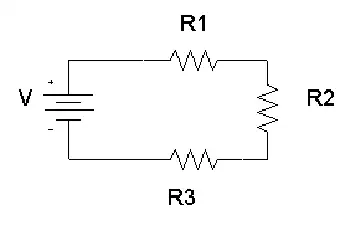

Electrical Resistance

Electrical resistance is the opposition to the flow of electric current in a material. It is measured in ohms (Ω) and depends on the conductor’s length, thickness, material, and temperature.


What is Electrical Resistance?

Electrical resistance is a fundamental concept in engineering that defines how much a material opposes the flow of electric current. Measured in ohms (Ω), resistance (Ω) plays a crucial role in circuit design, power distribution, and electronic applications.

✅ Measured in ohms (Ω) and calculated using Ohm’s Law

✅ Influenced by material, length, area, and temperature

✅ Key factor in circuit safety, design, and energy loss


Think of electricity moving like water through a pipe. If the pipe is narrow or obstructed, less water flows through it. Similarly, in a wire or conductor, certain materials make it harder for electrons to move freely. This obstruction results in energy loss, often seen as heat.

The ease or difficulty of electric charge movement depends on the conductivity of a material. Metals like copper allow current to flow easily, while rubber or glass inhibit it entirely. This behavior plays a key role in how systems are designed and protected. Discover how resistors are used in circuits to manage voltage and protect components by providing controlled resistance.


Electrical Resistance – Example Values by Material/Component

Material/Component Approx. Resistance Notes
Copper wire (1 meter, 1mm²) ~0.017 ohms Very low resistance, ideal for conductors
Aluminum wire (1m, 1mm²) ~0.028 ohms Higher resistance than copper
Iron wire (1m, 1mm²) ~0.10 ohms Often used in heating elements
Nichrome wire (1m, 1mm²) ~1.10 ohms High-resistance alloy used in toasters and heaters
Human body (dry skin) 1,000–100,000 ohms Varies greatly with moisture and contact
Incandescent light bulb ~240 ohms (cold) Resistance increases when hot
Resistor (carbon film) Fixed (e.g., 220 ohms) Used to control current in circuits
Air (dry) ~1 trillion ohms (insulator) Excellent natural insulator unless ionized
Superconductor 0 ohms Only at extremely low temperatures (near absolute zero)


Electrical Resistance Definition

Several factors affecting electrical resistance include the type of material, temperature, and the dimensions of the conductor. When an electric charge moves through a material, its ease of flow depends on the material’s conductivity. A high-conductivity material allows charges to move more freely, resulting in lower resistance. The resistance of a conductor increases with its length and decreases with its cross-sectional area. Therefore, the resistance of a wire is directly related to both its physical properties and the material from which it is made. The resistance of a conductor depends heavily on its length and cross-sectional area, as outlined in our resistance formula breakdown.

This opposing property is quantified using Ohm’s Law:

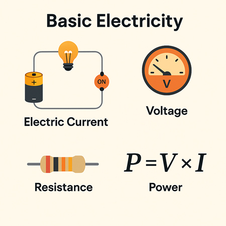
R = V / I

Where:

  • R is the resistive value in ohms

  • V is voltage (volts)

  • I is current (amperes)

Another useful expression involves material properties:

R = ρ × (L / A)

Where:

  • ρ is resistivity (material-specific)

  • L is length

  • A is cross-sectional area

These formulas show that the longer or thinner the conductor, the harder it is for current to move through it.


Unit of Electrical Resistance – The Ohm (Ω)

The ohm is the SI unit of resistance, named after German physicist Georg Ohm. One ohm is defined as the resistance between two points of a conductor when a potential difference of one volt causes a current of one ampere to flow.

Common multiples:

  • kΩ (kilo-ohm) = 1,000 ohms

  • MΩ (mega-ohm) = 1,000,000 ohms

Resistance can be measured using a multimeter, and is especially important in designing and troubleshooting power  and electronic circuits. To understand how voltage and resistance interact in a circuit, see our guide on Ohm’s Law.


Ohm’s Law and Circuit Function

Ohm’s Law helps us understand how voltage, current, and resistance relate. For example:

  • Increase the resistive load, and current drops.

  • Increase voltage with fixed resistance, and current rises.

These principles help control energy flow, prevent overloads, and design efficient systems.


Measuring and Expressing Opposition

The ohm (Ω) is the standard unit used to quantify this phenomenon. One ohm means that a current of one ampere flows when one volt is applied. Components with fixed values, like resistors, are labelled accordingly—e.g., 100 Ω, 1 kΩ, or 1 MΩ.

To measure the current-limiting capacity of a material, a digital multimeter is used. It applies a small voltage and calculates the resulting current flow to determine the opposition level. If you're working with different wire types, explore the unit of electrical resistance for conversion insights and resistance ranges.


Real-World Examples of Resistance

  • Heating Elements: Toasters, ovens, and electric heaters utilize high-resistance materials, such as nichrome wire.

  • Power Transmission: Long-distance wires are designed with low resistance to reduce energy loss as heat.

  • Electronic Components: Resistors regulate current in circuits, protecting components from overload.

For real-world scenarios involving current flow, our article on voltage drop explains how resistance affects electrical efficiency over distance.


Factors Affecting Electrical Resistance

  • The resistance of a conductor depends on:

    • Material – copper vs. aluminum vs. nichrome

    • Length – longer wires restrict current more

    • Thickness – wider wires allow easier flow

    • Temperature – many materials resist current more when heated

    Thus, the resistance of a wire can vary dramatically depending on where and how it’s used. Materials with high conductivity (like silver or copper) allow electrons to move with minimal restriction, whereas poor conductors like rubber greatly hinder charge movement.


Superconductors – Zero Resistance?

In some materials, when cooled to extremely low temperatures, resistance drops to zero. These superconductors enable electricity to flow without energy loss, but their use is limited to specialized fields, such as MRI machines or experimental power lines, due to cost and cooling requirements.


Frequently Asked Questions


What causes electrical resistance?

It results from collisions between electrons and atoms in a conductor, which convert energy into heat.


What is the formula for calculating it?

 R = V/I or R = ρ × (L / A)


How is it measured?

With a multimeter in ohms (Ω), using a small test voltage and measuring current. Learn how instruments like a digital multimeter are used to measure opposition to current flow in electrical systems.


Why is this concept important?

It controls current flow, prevents damage, and enables functions like heating or dimming.


Can resistance ever be zero?

Yes—in superconductors under specific extreme conditions.

Electrical resistance is a foundational concept in understanding how electricity behaves in materials and systems. From household wiring to high-voltage power lines and sensitive electronics, it plays a crucial role in determining safety, efficiency, and performance. For a broader view on electric flow and material response, read about electrical conductivity and current electricity.


Related Articles


Related News

Electricity Generation Power Production

Electricity generation is the process of producing electric power from various energy sources, including fossil fuels, solar, wind, hydro, and nuclear. It uses turbines and generators to convert mechanical or thermal energy into electrical energy for residential, commercial, and industrial use.


What is Electricity Generation?

Electricity generation is a process that involves producing electrical power from various sources.

✅ Converts mechanical, thermal, or chemical energy into electrical power

✅ Uses generators powered by steam, wind, water, or combustion

✅ Essential for powering homes, industries, and transportation


In the United States, power production from utility-scale generators was about 4.1 trillion kilowatt-hours (kWh) in 2019. Fossil fuels, including coal, natural gas, and petroleum, produced about 63% of the electricity, while nuclear energy produced around 20%. The remaining 17% was generated from renewable energy sources, including solar photovoltaics, wind turbines, and hydroelectric power production. To explore the full process from fuel to flow, see our detailed guide on how electricity is generated.


Electricity Generation Sources Compared

Energy Source How It Generates Electricity Global Usage (approx.) Carbon Emissions Renewable?
Coal Burns to heat water → steam → turbine spins generator 35% High No
Natural Gas Combusts to drive turbines directly or via steam 23% Moderate No
Nuclear Nuclear fission heats water → steam → turbine 10% Low No (but low-carbon)
Hydropower Flowing water spins turbines 15% Very Low Yes
Wind Wind turns large blades connected to a generator 7% Zero Yes
Solar PV Converts sunlight directly into electricity via photovoltaic cells 5% Zero Yes
Geothermal Uses Earth’s internal heat to create steam and turn turbines <1% Very Low Yes
Biomass Burns organic material to generate heat for steam turbines ~1.5% Moderate (depends on fuel) Partially


Hydroelectric Power Generation

Hydroelectric power production units utilize flowing water to spin a turbine connected to a generator. Falling water systems accumulate water in reservoirs created by dams, which then release it through conduits to apply pressure against the turbine blades, driving the generator. In a run-of-the-river system, the force of the river current applies pressure to the turbine blades to produce power. In 2000, hydroelectric generation accounted for the fourth-largest share (7 percent) of electricity production, at 273 billion kWh. Explore how water and electricity interact in hydroelectric plants, where falling water is converted into renewable energy.


Non-Hydro Renewable Energy Sources in Electricity Generation

Non-water renewable sources, including geothermal, refuse, waste heat, waste steam, solar thermal power plants, wind, and wood, contribute only small amounts (about 2 percent) to total power production. In 2019, power production from these sources totalled 84 billion kWh. The entire electric power industry production in 2019 was 3,800 billion kWh, with utilities' net production accounting for 3,015 billion kWh and net generation by non-utility power producers 785 billion kWh.


U.S. Electricity Generation by Energy Source: Trends and Shifts

The United States' share of electrical energy production from different sources has changed more rapidly since 2007 than ever since 1950. On the other hand, Canada's energy production is significantly less than that of the USA, primarily in Ontario and British Columbia. At least three trends are catalyzing these changes: (1) the low price of natural gas; (2) the rise in renewable and distributed generation due to falling costs; and (3) recent Federal and State policies impacting production. There are many innovative ways to generate electricity, from traditional fossil fuels to cutting-edge renewable technologies.


Fuel Source Diversity in U.S. and Canadian Electricity Production

Diversity is a key attribute in U.S. and Canadian electricity production. However, rather than being the result of a deliberative, long-term national initiative, this diversity has developed through spurts of growth in specific production technologies at different times. This is often due to policies, historical events, capital costs, fuel costs, and technological advancements.


Historical Growth of Electricity Generation by Energy Source

Most energy sources have experienced eras of significant capacity growth in terms of terawatt hours: hydro (1930‒1950, not shown); coal (1950-1985); nuclear (1960‒1980); natural gas (1990‒2010); and renewables (2005‒present). Nuclear energy is increasingly recognized as a key solution for achieving carbon reduction goals—learn how it contributes to net-zero emissions.


Changing U.S. Power Generation Mix: Centralized to Distributed Energy

The U.S. generation mix has undergone significant changes over the past few decades and is projected to continue evolving substantially. The U.S. generation fleet is transitioning from one dominated by centralized generators with high inertia and dispatchability to one more hybridized, relying on a mixture of traditional, centralized production and variable utility-scale and distributed renewable energy production.


Power Generation Technologies: From Diesel Engines to Wind Turbines

To generate power, various sources are utilized, including diesel engines, gas turbines, and nuclear power plants. Fossil fuels, including natural gas and coal, are burned to create hot gases that go through turbines, which spin the copper armature inside the generator and generate an electric current. In a nuclear power plant, nuclear reactions generate heat that is used to heat water, which then turns into steam and passes through a turbine to produce electricity. In a wind turbine, the wind pushes against the turbine blades, causing the rotor to spin and generating an electric current. In a hydroelectric turbine, flowing or falling water pushes against the turbine blades, causing the rotor to spin and generating an electric current. As the global energy landscape evolves, many experts are re-evaluating the role of nuclear power—learn more in our feature on the future of nuclear energy.


Electricity Generation by Utilities and Non-Utility Power Producers

To meet these immediate demands, utilities and nonutility power producers operate several electric generating units powered by various fuel sources. Renewable fuels, such as water, geothermal, wind, and other renewable energy sources like solar photovoltaics, are used as sources of power, alongside fossil fuels and uranium.


motor


diagram


Fossil Fuel Electricity Generation: Coal, Natural Gas, and Petroleum

Coal was the fuel used to generate the largest share (51.8 percent) of electricity in 2000, with natural gas and petroleum accounting for 16.1 percent and 3 percent, respectively. Steam-electric generating units burn fossil fuels, such as coal, natural gas, and petroleum, to produce steam. This steam is then used to turn a turbine into a generator, producing power. On the other hand, gas turbine generators burn fuels to create hot gases, which also go through a turbine, spinning the copper armature inside the generator and generating an electric current. Diesel engine generators are also used, where the combustion occurs inside the engine's cylinders, which are connected to the generator's shaft. The mechanical energy provided by the turbine drives the generator, which in turn produces energy.


Electricity Generation Trends and the Global Shift Toward Renewables

The production of electrical energy has experienced various eras of significant capacity growth in the United States, Canada, and other countries worldwide. The future of power production is transitioning to a more hybridized generation fleet that relies on a combination of traditional, centralized power production and variable utility-scale and distributed renewable energy sources. Low natural gas prices drive this transition, the rise of renewable and distributed energy sources, and recent Federal and State policies that impact generation. Discover the most common renewable energy sources powering the shift toward a cleaner, more sustainable electricity future.


Enhance your expertise in clean energy with our comprehensive Renewable Energy Grid Integration Training course. Designed for electrical professionals, this course covers the challenges and solutions associated with connecting solar, wind, and other renewable energy sources to the power grid. Stay ahead of industry trends, improve system reliability, and gain valuable skills to support the transition to a sustainable energy future. Enroll today and take the next step in your professional development.


Frequently Asked Questions

How is electricity generated from renewable energy sources?

Electricity is generated from renewable energy sources by converting the energy of the sun, wind, water, or earth into electrical energy. For example, solar photovoltaic panels generate power directly from sunlight, wind turbines to generate electricity from wind energy, and hydroelectric power plants generate power from falling water.


What are the different types of fossil fuels used?

The different types of fossil fuels used include coal, natural gas, and petroleum. Coal is the most commonly used fossil fuel for energy production, followed by natural gas and oil.


What are the advantages and disadvantages of using nuclear power plants for electricity generation?

Advantages of using nuclear power plants include that they produce a large amount of energy with a low amount of fuel, emit less carbon dioxide than fossil fuel power plants, and are not dependent on weather conditions like wind or solar power. Disadvantages include the risks associated with nuclear accidents, the high cost of building and maintaining nuclear power plants, and the long-term storage of nuclear waste.


How do gas turbines work to generate electricity?

Gas turbines burn natural gas or other fuels to heat air, which expands and drives the turbine. Finally, the turbine is connected to a generator that converts the mechanical energy of the turbine into electrical energy.


What is the role of steam turbines in electricity generation?

Steam turbines are commonly used to convert thermal energy from steam into mechanical energy that drives a generator. Steam is produced by burning fossil fuels or using heat from nuclear reactions or geothermal sources. The steam drives the turbine blades, which are connected to the generator to produce electricity.


What are some examples of non-renewable energy sources?

Examples of non-renewable energy sources used for power production include fossil fuels, such as coal, natural gas, and petroleum, as well as nuclear energy.


How is electricity generated and distributed in the United States?

Various power plants, including those powered by fossil fuels, nuclear energy, and renewable energy sources, generate electricity in the United States. Electric power is transported over a complex network of power lines and transformers to homes, businesses, and other consumers through local utility companies. The Federal Energy Regulatory Commission (FERC) and various state regulatory agencies regulate power distribution.


Related Articles


View more

Electricity Production

Electricity production converts primary energy into power via thermal, hydro, wind, and solar systems, optimizing efficiency, capacity factor, grid stability, transmission reliability, and emissions through turbines, generators, inverters, and advanced SCADA control.


What Is Electricity Production?

Electricity production converts energy to electric power, prioritizing efficiency, safety, and grid reliability.

✅ Conversion via turbines, generators, inverters, and transformers

✅ Control with SCADA, protective relays, and load-frequency regulation

✅ Optimization of efficiency, capacity factor, and emissions


Electricity Production continues to grow around the world, from a variety of energy power sources. In terms of world electricity generation, the US Department of Energy predicts advances strongly from 2004 to 2030. Global production increases by 2.4 percent per year over the projection period, from 16,424 billion kilowatthours in 2004 to 30,364 billion kilowatthours in 2030. Much of the growth in electric power demand is projected for nations outside the OECD. Although the non-OECD nations consumed 26 percent less electricity than the OECD nations in 2004, total generation in the non-OECD region in 2030 is projected to exceed generation in the OECD by 30 per cent. For context, the International Energy Outlook provides a concise overview of electricity generation trends worldwide today.

Total electricity demand in the non-OECD nations is expected to grow from 2004 to 2030 at an annual rate that is nearly triple the rate of growth for electricity demand in the OECD. The difference reflects the relative maturity of electricity infrastructure in the more developed OECD region, as well as the expectation that populations in the OECD countries generally will grow slowly or decline over the next 25 years. In addition, fast-paced growth in the developing non-OECD economies translates to rising standards of living and robust growth in consumer demand for lighting and appliances. Total electricity generation in the non-OECD region increases by an average of 3.5 percent per year in the IEO2007 reference case, as compared with a projected annual growth rate for OECD electricity generation that averages 1.3 per cent per year from 2004 to 2030. Among the energy end-use sectors, the most rapid growth in total world demand for electricity is projected for the buildings (residential and commercial) sectors.

Understanding the diversity of sources of electricity helps explain regional growth patterns in demand.

In Power plants, electricity Production involves the generation or creation of electric power, using rotating turbines attached to an energy generator. This mechanical manufacturing of electricity produces most commercially available electricity. Turbines are driven by a fluid which acts as an intermediate energy carrier. The fluids typically used are:

For readers new to plant design, this primer on how electricity is generated clarifies the roles of turbines, generators, and working fluids.

  • steam - Water is boiled by nuclear fission or the burning of fossil fuels (coal, natural gas, or petroleum). Some newer plants use the sun as the heat source: solar parabolic troughs and solar power towers concentrate sunlight to heat a heat transfer fluid, which is then used to produce steam. Another renewable source of heat used to drive a turbine is Geothermal power. Either steam under pressure emerges from the ground and drives a turbine or hot water evaporates a low boiling liquid to create vapour to drive a turbine.
  • water - Turbine blades are acted upon by flowing water, produced by hydroelectric dams or tidal forces,
  • wind - Most wind turbines generate electricity from naturally occurring wind. Solar updraft towers use wind that is artificially produced inside the chimney by heating it with sunlight.
  • hot gases - Turbines are driven directly by gases produced by the combustion of natural gas or oil. Combined cycle gas turbine plants are driven by both steam and gas. They generate power by burning natural gas in a gas turbine and use residual heat to generate additional electricity generation from steam. These plants offer efficiencies of up to 60%.

Hydropower and tidal technologies illustrate how water-based electricity remains a cornerstone in many regions.

Various other technologies have been studied and developed for power generation. Solid-state generation (without moving parts) is of particular interest in portable applications. This area is largely dominated by thermoelectric (TE) devices, though thermionic (TI) and thermophotovoltaic (TPV) systems have been developed as well. Typically, TE devices are used at lower temperatures than TI and TPV systems. Piezoelectric devices are used for power generation from mechanical strain, particularly in power harvesting. Betavoltaics are another type of solid-state power generator which produces electricity from radioactive decay. Beyond conventional turbines, a range of alternative electricity options are being explored for niche and distributed applications.

Fluid-based magnetohydrodynamic (MHD) electricity generation has been studied as a method for extracting electrical power from nuclear reactors and also from more conventional fuel combustion systems. These advanced concepts broaden our understanding of how we generate electricity under extreme conditions.

Electrochemical is also important in portable and mobile applications. Currently, most electrochemical power comes from closed electrochemical cells ("batteries"), which are arguably utilized more as storage systems than generation systems, but open electrochemical systems, known as fuel cells, have been undergoing a great deal of research and development in the last few years. Fuel cells can be used to extract power either from natural fuels or from synthesized fuels (mainly electrolytic hydrogen) and so can be viewed as either generation systems or storage systems depending on their use. In many systems the electricity generator ultimately interfaces with inverters and controls for grid integration.


Related Articles

View more

Ampere's Law Explained

Ampere’s Law describes the relationship between magnetic fields and electric currents, a fundamental concept in electromagnetism. It explains how current produces a magnetic force, guiding the design of circuits, solenoids, coils, and transformers in electrical engineering.


What is Ampere’s Law?

Ampere's Law is a fundamental principle in electromagnetism that describes the relationship between electric current and the resulting magnetic field.

✅ It states that the magnetic field around a closed path is proportional to the electric current passing through it.

✅ It is a fundamental principle of electromagnetism, linking current and magnetic flux.

✅ Used in analyzing coils, solenoids, transformers, and magnetic circuits.

Named after the French physicist André-Marie Ampère, this powerful principle helps us understand the behaviour of magnetic fields generated by electric currents. It is crucial to develop the numerous technologies we use on a daily basis. Understanding Ampere's Law is easier when explored alongside related concepts in basic electricity, which provide the foundation for electrical theory.

The principle states that the line integral of a magnetic field (B) around a closed loop is equal to the product of the permeability of free space (μ₀) and the net electric current (I) passing through the loop. This can be mathematically represented as:

∮ B⋅dl = μ₀I


Ampere’s Law at a Glance

Aspect Explanation Example / Application
Definition Magnetic field around a closed loop is proportional to the net electric current passing through it. Helps calculate fields in wires, coils, solenoids.
Formula ∮ B · dl = μ₀I (line integral of magnetic field equals permeability × current). Used in physics and engineering calculations.
Relation to Biot-Savart Law Both describe magnetic fields from current. Biot-Savart handles complex geometries; Ampere’s Law suits symmetrical setups. Magnetic field around a straight wire vs. irregular current paths.
Relation to Faraday’s Law Ampere’s Law: current → magnetic field. Faraday’s Law: changing magnetic field → induced EMF. Motors, generators, induction coils.
Role in Maxwell’s Equations One of the four fundamental equations of electromagnetism. Describes interaction of electric and magnetic fields.
Key Devices Guides design of solenoids, transformers, inductors, motors, and generators. Power systems, telecommunications, energy conversion.
Real-World Impact Essential to modern technology relying on electromagnetism. Smartphones, computers, power grids, antennas.


Ampere’s Law and Magnetism

The principle can be applied to determine the magnetic field around current-carrying wires and other conductive materials, as well as within various electrical systems. It is an essential part of Maxwell's equations, a set of four equations that serve as the foundation of classical electromagnetism. These equations relate electric and magnetic fields to their sources (electric charges and currents) and describe how they propagate through space. The connection between electricity and magnetism is central to electromagnetism, where Ampere’s Law works hand-in-hand with Faraday’s Law to explain induction.

It calculates magnetic fields through the Biot-Savart Law, a mathematical expression that relates the magnetic field produced by a steady electric current to the current's geometry. Both principles have specific applications, with the Biot-Savart Law being more suitable for cases with intricate current configurations. At the same time, it is typically employed when dealing with symmetrical setups.

Ampere’s Law has numerous real-life applications, especially in developing and understanding devices and systems that involve electromagnetism. For example, it is used in the design of transformers, inductors, and solenoids, as well as in various applications such as telecommunications systems, motors, and generators. By applying it, engineers can predict and control the magnetic fields generated in these devices, ensuring they function optimally and efficiently.


Gauss’ Law and Electric Fields Around a Circle of Radius

When studying electromagnetism, a common problem is analyzing the behavior of electric fields around a symmetric object, such as a circle of radius r or a sphere. Gauss’ Law is especially powerful in such cases, because it states that the electric flux through a closed surface is proportional to the net charge enclosed. This means the distribution of field lines can be calculated without solving complex integrals directly.

For a uniformly charged circle of radius r, the electric field at a point along the axis can be derived by considering the superposition of contributions from each charge element. The result reveals that the electric field depends on both the radius of the circle and the distance from the observation point. This demonstrates how Gauss’ Law simplifies problems with high symmetry.

Mathematically, the relationship is expressed as:

∮ E · dA = Q / ε₀

Here, E represents the vector field of the electric field, dA is the infinitesimal area vector on the closed surface, Q is the enclosed charge, and ε₀ is the permittivity of free space. By applying this principle, one can determine that electric fields radiate symmetrically outward from charges, with strength diminishing with distance according to the geometry of the surface considered.

The application of Gauss’ Law in analyzing a circle of radius r is connected to Ampere’s Law, as both emphasize symmetry and integration around closed paths. Where Ampere’s Law links magnetic fields to current, Gauss’ Law links electric fields to charge, and together they form part of Maxwell’s equations, the foundation of electromagnetism.


Relationship between Ampere's Law and Faraday's Law

The relationship between Ampere's Law and Faraday's Law of electromagnetic induction is apparent in the phenomenon of electromagnetic induction itself. When a changing magnetic field induces an electric current in a conductive material, the resulting magnetic field generated by this electric current, in turn, affects the overall magnetic field. It helps us understand how these interacting magnetic fields behave and influence each other.

Ampere's Law and its applications in various devices and systems enable numerous technological advancements. For instance, when designing motors and generators, engineers can utilize the principle to optimize the magnetic field within the device, resulting in higher efficiency and improved performance. Ampere’s Law is also linked to the behavior of capacitance and inductance, both of which are essential in circuits and energy storage systems.

In the telecommunications realm, it helps explain the propagation of electromagnetic waves in cables and antennas. It enables engineers to design systems that minimize signal loss and maximize data transfer rates, ensuring that our smartphones, computers, and other devices remain connected and up-to-date.

By understanding the magnetic field lines and the interaction between electric current and magnetic fields, Ampere's Law opens doors to scientific discovery and innovation in numerous fields. From determining the magnetic field at a distance to the thumb rule and hand rule applications, this fundamental principle plays a crucial role in shaping the world of electromagnetism and the technology that surrounds us.


Electromagnetism

It is a cornerstone of electromagnetism that helps us understand the relationship between electric current and how it creates a magnetic field. It is a vital component of Maxwell's equations and intricately connected to other principles, such as Faraday's Law and Biot-Savart's Law. Ampere's Law has numerous applications in real-life scenarios and is essential for the functioning of many devices and systems that rely on electromagnetism. Its significance in the development of technology cannot be overstated, as it continues to drive scientific discovery and innovation. For students exploring fundamentals, the history of concepts like what is electricity and its evolution in electricity history provides valuable context to Ampere’s discoveries.


How does Ampere’s Law relate to Faraday's Law and Biot-Savart Law?

They are all essential principles in electromagnetism that describe various aspects of the interaction between electric currents and magnetic fields. Although each addresses different aspects, these are interrelated, forming a more comprehensive understanding of electromagnetism.

It describes the relationship between an electric current and its generated magnetic field. Mathematically, it states that the line integral of the magnetic field (B) around a closed loop is proportional to the net electric current (I) passing through the loop:

∮ B⋅dl = μ₀I

Ampere’s Law is useful for calculating magnetic fields in highly symmetrical situations, such as around straight wires, loops, or solenoids.

Faraday's Law: Faraday's Law of Electromagnetic Induction describes how a changing magnetic field induces an electromotive force (EMF) in a conductor. Mathematically, it states that the induced EMF is proportional to the rate of change of the magnetic flux (ΦB) through a closed loop formed by the conductor:

EMF = -dΦB/dt

Faraday's Law is fundamental to understanding the operation of devices such as generators, transformers, and induction motors, which rely on converting mechanical and electrical energy.

The Biot-Savart Law calculates the magnetic field at any point in space due to a specific current distribution. Mathematically, it can be expressed as:

dB = (μ₀ / 4π) * (Idl × r̂) / r²

The Biot-Savart Law is particularly useful for calculating magnetic fields in complex current configurations without symmetry.


Ampere's Law and Biot-Savart Law

Ampere's Law and Biot-Savart Law: Both deal with the magnetic field generated by an electric current. While the first is useful for calculating magnetic fields in symmetric situations, the Biot-Savart Law applies to a wider range of configurations, including those with intricate geometries. It can be derived from the Biot-Savart Law for specific symmetric situations.


Ampere's Law and Faraday's Law

Ampere's Law and Faraday's Law: These laws are related through Maxwell's equations, which connect electric and magnetic fields. While the first deals with the magnetic field generated by a steady electric current, Faraday's Law deals with the induced EMF resulting from a changing magnetic field. Both laws contribute to our understanding of electromagnetic phenomena and play a role in operating devices that rely on electromagnetism.

The Biot-Savart Law enables us to determine the magnetic field generated by a specific current distribution. Faraday's Law describes how a changing magnetic field can induce an EMF. In cases where the magnetic field changes due to a varying current, the Biot-Savart Law can be used to calculate the magnetic field, and then Faraday's Law can be applied to determine the induced EMF.

All three are interconnected principles in electromagnetism, each addressing a specific aspect of the interaction between the electric current and the electric field. Together, these form a more comprehensive understanding of electromagnetic phenomena and provide a basis for analyzing and designing various devices and systems that rely on electromagnetism.


Related Articles


View more

Watthour Meter Explained

A watthour meter measures electrical energy consumption in kilowatt-hours (kWh) for residential, commercial, and industrial applications, ensuring accurate billing, energy management, and compliance with utility standards.


What is a Watthour Meter?

✅ Measures total electrical energy in kilowatt-hours (kWh) over time

✅ Supports accurate billing, energy monitoring, and demand analysis

✅ Used in residential, commercial, and industrial revenue metering


Advancements in Watthour Meter Technology and Energy Measurement

Watthour meter technology plays a crucial role in modern electrical engineering and maintenance by providing accurate measurement and monitoring of energy consumption. These devices are indispensable for managing energy efficiency, optimizing power distribution, and ensuring compliance with regulatory standards. For electrical professionals, understanding how they operate and are maintained is essential to minimize energy losses and enhance the reliability of electrical systems. With the growing demand for precise energy data in both residential and industrial applications, staying informed about advancements in watthour meter technology is more important than ever. Understanding how a watthour is calculated helps clarify how a watthour meter tracks total energy usage for accurate billing. 


How Induction Type Single Phase Watt Hour Meters Work

Induction type meters, commonly used as single phase watt hour meters, provide accurate measurement of electrical energy consumption in residential and small commercial installations.

Your electric utility is not too interested in how much power you're consuming for one ap­pliance or even how much power a single household is drawing at any given time. By far the greater concern is the total energy that is used over a day, a week, a month or a year. Electrical energy is measured in watt-hours or, more commonly for utility pur­poses, in kilowatt-hours (kWh). The device that measures this consumption is the watt-hour meter or kilowatt-hour meter. For a deeper understanding of the units used in metering, see our guide on electrical energy and how it is measured in kilowatt-hours.

The most common method for measuring electrical energy is by using a small elec­tric motor device, whose speed depends on the current, and thereby on the power at a constant voltage. The number of turns of the motor shaft, in a given length of time, is di­rectly proportional to the number of watt hours consumed. The motor is placed at the point where the utility wires enter the house, apartment or building. This is usually at a point where the voltage is 234 V. This is split into some circuits with 234 V, for heavy-duty appliances such as the oven, washer and dryer, and the general household circuits for lamps, clock radios and television sets. The principles behind watthour meters are closely tied to basic electricity and the relationship between active power and time.


Understanding the Spinning Disk in Electromechanical Watthour Meters

You've surely seen the little disk in the utility meter going around and around, sometimes fast, other times slowly. Its speed depends on the power you're using. The total number of turns of this little disk, every month, determines the size of the bill you will get, as a function also, of course, of the cost per kilowatt hour for electricity.

Kilo-watt-hour meters count the number of disk turns by means of geared, rotary drums or pointers. The drum-type meter gives a direct digital readout. The pointer type has several scales calibrated from 0 to 9 in circles, some going clockwise and others go­ing counterclockwise. Mechanical and electronic meters both rely on the concepts of electrical resistance and current to provide precise readings.


How to Read a Pointer-Type Watthour Meter Accurately

Reading a pointer-type utility meter is a little tricky because you must think in whatever direction (clockwise or counterclockwise) the scale goes. An example of a pointer-type utility meter is shown in Fig. 3-11. Read from left to right. For each little meter, take down the number that the pointer has most recently passed. Write down the rest as you go. The meter in the figure reads 3875 kWh. If you want to be really pre­cise, you can say it reads 3875-1/2 kWh. To place watt hour metering in historical context, explore our history of electricity page and learn how early meters evolved into today’s advanced devices.


Fig. 3-11 An example of a utility kilo-watthour meter. The reading is a little more than 3875 kWh.


Related Articles


View more

Geothermal Electricity Explained

Geothermal electricity delivers renewable baseload power by converting subsurface heat through turbines, generators, ORC binary cycles, and heat exchangers, enabling grid integration, high capacity factor, low emissions, and efficient power plant control systems.


What Is Geothermal Electricity?

Geothermal electricity converts geothermal heat to power using turbines and generators for low-emission baseload.

✅ Uses steam, flash, and binary cycle power plant designs

✅ Employs ORC, heat exchangers, and closed-loop systems

✅ Provides baseload, high capacity factor, and grid stability


Geothermal Electricity is produced through geothermal power plants capturing the thermal energy contained in the Earth. Use of geothermal energy is based thermodynamically on the temperature difference between a mass of subsurface rock and water and a mass of water or air at the Earth's surface. This temperature difference allows production of thermal energy that can be either used directly or converted to mechanical or Geothermal Electricity. For context on broader methods and terminology, see this overview of electricity generation and how heat energy is converted to power.

Commercial exploration and development of Plant Geothermal water generated into Electricity to date have focused on natural geothermal reservoirs—volumes of rock at high temperatures (up to 662°F or 350°C) and with both high porosity (pore space, usually filled with water) and high permeability (ability to transmit fluid). The thermal energy is tapped by drilling wells into the reservoirs. The thermal energy in the rock is transferred by conduction to the fluid, which subsequently flows to the well and then to the Earth's surface where it can be converted into Geothermal Electricity. This well-to-turbine pathway is a fundamental part of electricity production from thermal resources.

There are several types of natural geothermal reservoirs. All the reservoirs developed to date for electrical energy are termed hydrothermal convection systems and are characterized by circulation of meteoric (surface) water to depth. The driving force of the convection systems is gravity, effective because of the density difference between cold, downward-moving, recharge water and heated, upward-moving, thermal water. A hydrothermal convection system can be driven either by an underlying young igneous intrusion or by merely deep circulation of water along faults and fractures. Depending on the physical state of the pore fluid, there are two kinds of hydrothermal convection systems: liquid-dominated, in which all the pores and fractures are filled with liquid water that exists at temperatures well above boiling at atmospheric pressure, owing to the pressure of overlying water; and vapor-dominated, in which the larger pores and fractures are filled with steam. Liquid-dominated reservoirs produce either water or a mixture of water and steam, whereas vapor-dominated reservoirs produce only steam, in most cases superheated. Because water acts as the primary working fluid in most systems, understanding the interplay of water and electricity helps clarify operational safety and design.

These hydrothermal systems are distinct from hydroelectricity produced by river impoundments, even though both ultimately rely on water as a medium.

Although geothermal energy is present everywhere beneath the Earth's surface, its use is possible only when certain conditions are met: (1) The energy must be accessible to drilling, usually at depths of less than 2 mi (3 km) but possibly at depths of 4mi (6–7km) in particularly favorable environments (such as in the northern Gulf of Mexico Basin of the United States). (2) Pending demonstration of the technology and economics for fracturing and producing energy from rock of low permeability, the reservoir porosity and permeability must be sufficiently high to allow production of large quantities of thermal water. (3) Since a major cost in geothermal development is drilling and since costs per meter increase with increasing depth, the shallower the concentration of geothermal energy the better. (4) Geothermal fluids can be transported economically by pipeline on the Earth's surface only a few tens of kilometers, and thus any generating or direct-use facility must be located at or near the geothermal anomaly. When these conditions align, engineered systems can efficiently generate electricity from accessible geothermal gradients.

The use of geothermal energy for Geothermal Electricity has become widespread because of several factors. Countries where geothermal resources are prevalent have desired to develop their own resources in contrast to importing fuel for power generation. In countries where many resource alternatives are available for power generation, including geothermal, geothermal has been a preferred resource because it cannot be transported for sale, and the use of geothermal energy enables fossil fuels to be used for higher and better purposes than power generation. Also, geothermal steam has become an attractive power generation alternative because of environmental benefits and because the unit sizes are small (normally less than 100 MW). Moreover, geothermal plants can be built much more rapidly than plants using fossil fuel and nuclear resources, which, for economic purposes, have to be very large in size. Electrical utility systems are also more reliable if their power sources are not concentrated in a small number of large units. In energy planning, geothermal is often evaluated alongside other forms of alternative electricity to balance portfolios and grid resilience. Many developers also highlight its contribution to green electricity targets thanks to low lifecycle emissions.


Related Articles

View more

Voltage Drop Calculator

A voltage drop calculator helps electricians and engineers estimate line loss, wire size, and circuit efficiency. By inputting conductor length, current, and material, it ensures proper electrical design, safe voltage regulation, and compliance with power distribution standards.


What is a Voltage Drop Calculator?

A voltage drop calculator (VDC) is crucial for any electrical engineer or designer. It enables them to calculate VD accurately, which is essential for maintaining an efficient and safe electrical system.

✅ Quickly estimates voltage loss in electrical circuits

✅ Helps select the correct wire size for load and distance

✅ Supports NEC code compliance and system efficiency


Power Quality Analysis Training

Power Factor Training

Request a Free Power Quality Training Quotation

Voltage drop calculators are used in various applications, including residential, commercial, and industrial settings, and offer several benefits, such as accurate calculations, time savings, cost reduction, and hazard prevention. Additionally, engineers can ensure the electrical system operates efficiently and safely by considering factors such as cable sizing, wire gauge, and the type of conductor used. Want the full math? Visit our voltage drop formula guide for detailed equations and examples.

There are numerous VDCs available on the internet, and one of the best places to find them is on Google Play.


Applications of Voltage Drop Calculators

VDCs are used in various residential, commercial, and industrial applications. For instance, in residential applications, VDCs help determine the appropriate wire size for the electrical service panel, the length of wires, and the type of installation, ensuring that the electrical system operates correctly and safely. Additionally, VD formulas can be used to calculate resistance and reactance in both single-phase and three-phase electrical systems. It is measured in feet over a specified length.

In commercial applications, voltage drop calculators are used to design and maintain electrical systems in buildings such as hospitals, schools, and offices. These buildings require careful design to ensure that they meet the power requirements of the building and are safe for occupants. VDCs play a crucial role in this process by calculating the VD in the circuit and determining the appropriate wire size and other specifications.

In industrial applications, VDCs are used to design and maintain electrical systems in factories and other industrial settings. These systems require careful design to ensure they meet the equipment's power requirements and are safe for workers. VDCs determine the circuit's VD, the appropriate wire size, and other specifications to ensure that the electrical system operates efficiently and safely. For an overview of the general principles of voltage drop across AC and DC systems, read our article.


Benefits of Using a VDC

Using a VDC offers several benefits, including:

Accurate Calculations: VDCs use complex algorithms to calculate VD accurately. This ensures that the electrical system operates efficiently and safely.

Saves Time: VDCs save time by automating the process of calculating VD. This allows engineers to focus on other aspects of the design process, such as equipment selection and installation.

Reduces Costs: By accurately calculating VD, engineers can select the appropriate wire size and other specifications, thereby reducing the cost of the electrical system.

Prevents Hazards: Accurate calculation of VD prevents electrical hazards, including fires and shocks. 


FREE Voltage Drop Calculator 


Cable Sizing and Wire Gauge

One of the most critical factors to consider when designing an electrical system is cable sizing and wire gauge. The conductor's or wire gauge's size is critical in determining the amount of current that can flow through the conductor without causing excessive VD or overheating. American Wire Gauge (AWG) is the standard system used to specify wire sizes, providing a range of conductor sizes based on the wire's cross-sectional area. Additionally, the National Electrical Code (NEC) provides guidelines for ampacity and voltage drop (VD) for various conductor sizes and types of installations.


Copper or Aluminum Conductors

The type of conductor used in an electrical system also affects the voltage drop (VD). Copper and aluminum conductors are the most commonly used materials, with copper being preferred due to its lower resistance and higher conductivity. However, aluminum conductors are less expensive and commonly used in larger conductors and power transmission lines.


Frequently Asked Questions


How do I calculate voltage drop?

To calculate VD, you can use the VD formula, which is V = IR, where V is the voltage drop, I is the current flowing through the conductor, and R is the resistance of the conductor. By knowing the current, resistance, and length of the conductor, you can calculate the VD and determine whether it falls within acceptable limits.


How do I use it?

To use a VDC, you need to input the current flowing through the conductor, the length of the conductor, and the wire gauge or cable size. The tool then uses complex algorithms to calculate the VD in the circuit accurately. Based on the results, you can determine the appropriate wire size, cable length, and other specifications necessary to maintain an efficient and safe electrical system.


How is voltage drop calculated in a circuit?

VD is calculated in a circuit using Ohm's Law, which states that the VD across a conductor is equal to the product of the current and resistance. By knowing the current, resistance, and length of the conductor, you can calculate the VD and determine whether it falls within acceptable limits.


What factors affect voltage drop in a circuit?

The factors that affect VD in a circuit include the current flowing through the conductor, the length of the conductor, the resistance of the conductor, and the wire gauge or cable size. Other factors, such as the type of conductor and installation, can also affect VD.


Why is it important to calculate voltage drop?

Calculating VD is essential in maintaining an efficient and safe electrical system. VD can impact the performance of electrical equipment and devices, leading to hazards such as fires and electrical shock. By accurately calculating VD, engineers can select the appropriate wire size, cable length, and other necessary specifications to maintain an efficient and safe electrical system.


What are the benefits of using a VDC?

Using a VDC offers several benefits, including accurate calculations, time savings, cost reduction, and hazard prevention. By accurately calculating VD, engineers can select the appropriate wire size and other specifications, thereby reducing the cost of the electrical system. In addition, calculating VD accurately can prevent electrical hazards such as fires and shocks.


Are there any limitations to using a VDC?

While VDCs offer numerous benefits, they also have some limitations. For example, they rely on the accuracy of the input parameters, but may overlook other factors that can affect voltage drop, such as temperature and ambient conditions. Additionally, they may not be suitable for complex electrical systems.


What is the voltage drop per 100 ft?

The VD per 100 ft depends on various factors, including the current flowing through the conductor, the conductor's length, its resistance, and the wire gauge or cable size. Therefore, it is essential to calculate the VD accurately to determine the appropriate wire size and cable length necessary to maintain an efficient and safe electrical system.


What is a rule of thumb for voltage drop?

The rule of thumb for VD is that the VD in a circuit should not exceed 3% for power circuits and 5% for lighting circuits. These values are based on the National Electrical Code (NEC) guidelines, ensuring the electrical system operates efficiently and safely.

Southwire Voltage Drop Calculator


Related Pages


View more

Sign Up for Electricity Forum’s Newsletter

Stay informed with our FREE Newsletter — get the latest news, breakthrough technologies, and expert insights, delivered straight to your inbox.

Electricity Today T&D Magazine Subscribe for FREE

Stay informed with the latest T&D policies and technologies.
  • Timely insights from industry experts
  • Practical solutions T&D engineers
  • Free access to every issue

Download the 2025 Electrical Training Catalog

Explore 50+ live, expert-led electrical training courses –

  • Interactive
  • Flexible
  • CEU-cerified