Windmills For Electricity Explained


windmills for electricity

Windmills for electricity use wind energy to generate clean, renewable power. These wind turbines convert kinetic energy into electrical energy, reducing carbon emissions and dependence on fossil fuels. 


What are Windmills for Electricity?

Windmills for electricity are modern devices that transform kinetic wind energy into electrical power.

✅ Harness renewable energy for clean power

✅ Reduce carbon footprint and dependence on fossil fuels

✅ Support sustainable power generation worldwide

Windmills for electricity are part of a broader shift toward renewable energy, providing clean alternatives to fossil fuels for homes, businesses, and utilities.


History of Windmills

Windmills for electricity - Mankind has been harnessing the wind's energy for many years. From Holland to traditional farms around the world, windmills were used in the past for pumping water through primitive irrigation systems or to grind grain. Then, the wind turned large "sails" that were connected by a long vertical shaft, which was attached to a grinding machine or a wheel that turned and drew water from a well. Today's turbines harness the energy of the wind to turn large metal blades, which in turn spin a generator that produces electric power. Alongside wind, other renewable energy sources like solar, biomass, and tidal energy are shaping a diversified and sustainable energy future.

From the mid-1970s to the mid-1980s, the United States government collaborated with industry to advance windmill technology for power generation and enable the development of large commercial wind turbines. NASA led this effort at the Lewis Research Center in Cleveland, Ohio, and it was an extraordinarily successful government research and development activity.


National Science Foundation

With funding from the National Science Foundation and later the Department of Energy (DOE), a total of 13 experimental wind turbines were put into operation, including four major wind turbine designs. This research and development program pioneered many of the multi-megawatt turbine technologies in use today, including steel tube towers, variable-speed generators, composite blade materials, partial-span pitch control, as well as aerodynamic, structural, and acoustic engineering design capabilities. The large Windmills For Electricity developed under this effort set several world records for diameter and power output. The Mod-2 wind turbine cluster produced a total of 7.5 megawatts of power in 1981. Government incentives, such as alternative energy tax credits, have played a major role in expanding wind power adoption across North America.


Wind Turbine Technology

In 1987, the Mod-5B was the largest single wind turbine operating in the world with a rotor diameter of nearly 100 meters and a rated power of 3.2 megawatts. It demonstrated an availability of 95 percent, an unparalleled level for a new first-unit wind turbine. The Mod-5B featured the first large-scale variable-speed drive train and a sectioned, two-blade rotor, which enabled easy transport of the blades.

Later, in the 1980s, California provided tax rebates for ecologically harmless wind turbines. These rebates helped fund the first major deployment of wind power for the utility grid. These turbines gathered in large wind parks such as at Altamont Pass, would be considered small and uneconomical by modern wind power development standards.

In the 1990s, as aesthetics and durability became more important, turbines were placed atop steel or reinforced concrete towers. Small generators are connected to the ground tower, and then the tower is raised into position. Larger generators are hoisted into position atop the tower, and a ladder or staircase is located inside the tower to allow technicians to reach and maintain the generator.

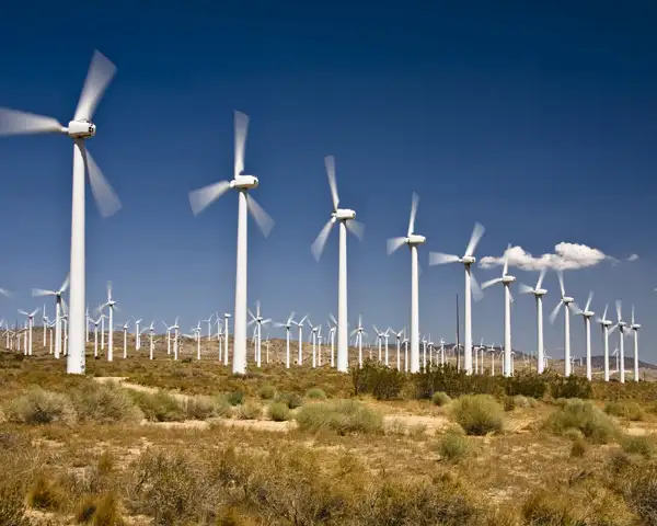
Originally, wind turbines were built right next to where their power was needed. With the availability of long-distance electric power transmission, wind generators are now often on wind farms in windy locations, and huge ones are being built offshore, sometimes transmitting power back to land using high-voltage submarine cable. Since wind turbines are a renewable means of generating power, they are being widely deployed, but their cost is often subsidized by taxpayers, either directly or through renewable energy credits. Much depends on the cost of alternative energy sources. The cost of wind generators per unit of power has been decreasing by about 4% per year.


Modern Wind Turbines

The most modern generations of Windmills for electricity are more properly called wind turbines, or wind generators, and are primarily used to generate electric power. Modern windmills are designed to harness the energy of the wind and convert it into electric energy. The largest wind turbines can generate up to 6 MW of power (for comparison, a modern fossil fuel power plant generates between 500 and 1,300 MW). Many large-scale renewable energy projects now combine wind farms with solar and storage systems, ensuring reliable, clean power for communities worldwide.

Small wind turbines can generate as little as a few kilowatts, while larger models produce up to 100 kilowatts or more, depending on design and location. These devices capture moving air, and as wind turbines operate, the kinetic energy generated can be used directly or sent into the electrical grid. On a utility scale, wind farms combine many large turbines to deliver massive amounts of energy, powering thousands of homes and businesses. This range of applications, from residential to industrial, demonstrates the versatility of wind technology in meeting diverse energy needs.

Related News

Static Electricity

Static electricity is a fascinating phenomenon that can be both awe-inspiring and dangerous. Understanding its basic concepts, including the movement of charged particles and the causes of positive and negative charge imbalance, is crucial in preventing potential hazards. By taking preventive measures such as grounding equipment and surfaces, using anti-static materials, and increasing humidity, we can avoid the buildup of static charges and protect ourselves and our environment from its hazards. It is also important to understand the potential dangers and take appropriate precautions, particularly when working with flammable or explosive materials. With this knowledge, we can safely harness the power and explore its many fascinating properties.


What is static electricity?

It results from the movement of charged particles, called electrons and particles called protons, which make up the atoms of matter. Atoms are made up of protons, neutrons, and electrons. Protons have a positive charge, electrons have a negative charge, and neutrons have no charge. In most atoms, the positive charge of the protons is balanced by the negative charge of the electrons, resulting in a neutral object.

However, when two objects come in contact, the extra electrons from one object may transfer to the other, creating a charge imbalance. This results in one object having a positive charge and the other having a negative electric charge. These charges repel, and when the objects are separated, they retain the charges, creating a static charge.


What causes static electricity?

As previously mentioned, it is caused by the movement of charged particles. When there is a charge imbalance between two objects, it can create a static charge. This can occur through friction, conduction, or induction.

Friction occurs when two objects rub against each other, causing electrons to transfer from one object to the other. For example, this is why you may experience it when you rub a balloon against your hair, causing your hair stand to stand up.

Conduction occurs when two objects come in contact and transfer electrons between them. For example, when you touch a doorknob, you may receive a static shock if the doorknob is charged.

Induction occurs when a charged object is brought near a neutral object, causing a charge to be induced in the neutral object.


How does static electricity work?

It creates a charge imbalance between two objects, resulting in one object having a positive charge and the other having a negative charge. These charges repel each other, and when the objects are separated, they retain the charges, creating a static charge.

When a charged object comes in contact with a neutral object, the charge may transfer, resulting in a static shock. This occurs when the charge imbalance is released as a spark. Static shocks are usually harmless but can sometimes be dangerous, particularly in hazardous environments.


Can static electricity hurt you?

While it is usually harmless, it can sometimes be dangerous. A static shock occurs when a charged object comes in contact with a person or object that is not charged. The shock results from the charge imbalance being released as a spark. The shock can be uncomfortable, and in rare cases, it can cause serious injury, mainly if it occurs in a hazardous environment, such as around flammable materials.


What are the dangers of static electricity?

It can be dangerous in certain situations, such as when working with flammable or explosive materials. A spark from it can ignite flammable gases or vapours, leading to fires or explosions. In industrial settings, it is important to take precautions to prevent the buildup of static charges and to discharge any charges that may occur.


How do you discharge static electricity?

There are several ways to discharge it, including:

  • Grounding: Connecting the charged object to a ground source such as the earth, which dissipates the excess charge.
  • Anti-static materials: Wearing clothes made of anti-static materials or using anti-static sprays can prevent the buildup of static charges.
  • Humidification: Increasing the humidity in a room can help reduce a buildup by adding moisture to the air.
  • Use of ionizers: Ionizers can neutralize it by releasing negative ions into the air.
  • Proper grounding of equipment: Ensuring that all equipment and surfaces are properly grounded can prevent the buildup of static charges.


How can you prevent static electricity?

Preventing buildup involves taking several steps, such as:

  • Using anti-static materials: Clothing made of anti-static materials or anti-static sprays can prevent the buildup of static charges.
  • Grounding: Ensuring that all equipment and surfaces are properly grounded can prevent the buildup of static charges.
  • Humidification: Increasing the humidity in a room can help reduce a buildup by adding moisture to the air.
  • Proper handling of flammable materials: When working with flammable or explosive materials, it is important to take proper precautions to prevent a buildup and discharge of any charges.
  • Using equipment designed for use in hazardous environments: Equipment designed for use in hazardous environments is designed to prevent a buildup and sparks from occurring.

In addition to these preventive measures, it is important to understand the basics of static electricity and the factors that contribute to its buildup. This knowledge can help individuals take steps to avoid buildup and prevent any potential hazards.


Van de Graaff Generator: An Experiment with Static Electricity

One fascinating example of this is the Van de Graaff generator. This device was invented in 1929 by Robert J. Van de Graaff and is used to generate high voltages of static electricity. The generator transfers electrons from a moving belt to a metal sphere, creating a charge imbalance between the two objects.

This charge imbalance creates a strong electric field, which can be used to demonstrate various phenomena. For example, the electric field can cause hairs on a person's head or arm to stand up due to the repulsion between the positively charged hair and the positively charged metal sphere.


View more

What is Medium Voltage iExplained

Medium voltage refers to electrical systems operating between 1 kV and 35 kV, used in industrial facilities, substations, and utility power distribution networks to safely transfer energy between low-voltage and high-voltage levels.


What is Medium Voltage?

Medium voltage refers to the electrical range between 1 kV and 35 kV, bridging the gap between low- and high-voltage systems for efficient energy transfer and safe power distribution across industrial, commercial, and utility applications.

✅ Used in substations, industrial plants, and utility grids

✅ Defined by IEEE and IEC classification standards

✅ Supports reliable energy transmission and electrical safety

A medium voltage (MV) system is crucial for distributing electricity in industrial, commercial, and institutional settings. It acts as the intermediary between high-voltage transmission lines and low-voltage consumer systems, ensuring efficient power delivery within a facility. This article provides a comprehensive overview of a medium voltage system, including its definition, applications, equipment, safety practices, and relevant standards. Understanding these concepts is vital for electrical professionals to ensure the safe and efficient operation of this critical power infrastructure. Medium voltage systems are essential links in 3 phase electricity networks, where balanced power delivery ensures efficient energy distribution across industrial and utility infrastructures.

Understanding medium voltage systems is essential for electrical professionals working in industrial, commercial, and institutional settings. This article provides a comprehensive overview of what constitutes medium voltage, its role in the power grid, common applications, and safety considerations. By grasping these key concepts, professionals can ensure the safe and efficient design, operation, and maintenance of these critical power systems. Understanding 3 phase power helps explain how medium voltage circuits maintain stable electrical loads in substations and manufacturing facilities.


Voltage Levels and Classifications

In the realm of electrical engineering, voltage levels are broadly categorized to distinguish their applications and safety requirements.  These categories range from LV, typically used for residential applications, to extra high voltage (HV) and ultra-high voltages employed in HV transmission across long distances. MV occupies a middle ground, generally falling between 1,000 volts (600 volts in some instances) and 35,000 volts (35 kV). This distinguishes it from HV used in transmission and lower voltages used in end-user applications. Many 3 phase transformers and pad-mounted transformer installations operate at medium voltage levels, stepping electrical energy down for safe use in local distribution systems.

To better visualize this, imagine electricity flowing like a river through the electrical grid. V is like the force propelling the water, and different levels represent different sections of the river. HV is like a powerful, fast-flowing river capable of transporting electricity over long distances. MV, on the other hand, is like a branching stream that distributes the water (electricity) to various destinations. It's the crucial link between the high-powered transmission lines and the LV systems that deliver power to individual consumers. For a foundational understanding, review basic electricity concepts that explain how V, current, and resistance interact within medium voltage electrical systems.


What is Medium Voltage Applications?

Medium voltage systems have a wide range of applications in industrial, commercial, and institutional settings. In industrial facilities, they power large motors, heavy machinery, and industrial processes. Commercial buildings utilize what is MV for HVAC systems, lighting, and other electrical loads. Institutions such as hospitals and universities rely on MV to support their critical operations.

The use of MV is increasing. Historically, it was mainly used for subtransmission and primary distribution, supplying distribution transformers that step down the voltage to LV for end-use equipment. It was also traditionally used in industries for MV motors. However, with advancements in power electronics and semiconductor technology, new applications are emerging, such as:

  • MV DC Distribution Grids: These grids offer higher efficiency in long-distance transmission and are being implemented in collector grids for wind and photovoltaic parks.

  • Renewable Energy Integration: MV systems play a vital role in integrating renewable energy sources into the power grid, enabling the transition to a more sustainable energy future.

The principles of active power apply directly to medium voltage operations, where real power flow efficiency determines the overall performance of industrial and commercial grids.


Frequently Asked Questions


How does MV differ from low and HV?

Medium voltage occupies a middle ground between LV, typically used for residential applications, and HV, employed for long-distance transmission. It's the "in-between" voltage level that allows us to efficiently distribute power to different consumers.


What is Medium Voltage Range ?

Generally, MV falls between 1,000 volts (600 volts in some instances) and 35,000 volts (35 kV). This range can vary slightly depending on regional standards and practices.  For example, ANSI standards in the US include voltages up to 69 kV in the MV class, while IEC standards use 1000 Vrms as the threshold between low and HV in AC installations.


What is MV in industrial, commercial, and institutional power systems?

Medium voltage is distributed within these facilities to power various equipment and loads. It's the primary level used within these settings before being stepped down to LV for end-use.


What are common applications of MV systems?

Common applications include powering large motors and machinery in industrial settings, as well as HVAC and lighting systems in commercial buildings, and critical operations in institutions such as hospitals.  Emerging applications include microgrids and the integration of renewable energy.


What are the key standards and regulations governing MV systems?

Key standards include those from ANSI, IEEE, and NEC, which provide guidelines for the design, installation, and safety of MV systems. These standards ensure that MV systems are implemented in a safe and consistent manner.

A Medium Voltage system is crucial for distributing electricity in industrial, commercial, and institutional settings. It acts as the intermediary between HV transmission lines and LV consumer systems, ensuring efficient power delivery within a facility. This article provides a comprehensive overview of a medium voltage system, including its definition, applications, equipment, safety practices, and relevant standards. Understanding these concepts is vital for electrical professionals to ensure the safe and efficient operation of this critical power infrastructure.


Related Articles


View more

Norton's Theorem

Norton’s Theorem simplifies electrical circuit analysis by reducing any complex linear network to an equivalent current source in parallel with a resistor, enabling easier calculation of load current, evaluation of resistance, and solving practical problems.


What is Norton’s Theorem?

Norton’s Theorem states that any linear electrical network with sources and resistances can be reduced to an equivalent current source in parallel with a single resistor.

✅ Represents complex circuits as a simple current source and resistor

✅ Simplifies load current and resistance calculations

✅ Enhances circuit analysis for power systems and electronics


Understanding Norton's Theorem

Norton's Theorem is a foundational principle in electrical engineering, used to simplify the analysis of linear electronic circuits. This theorem, often taught alongside Thevenin's Theorem, provides a practical method for reducing complex circuits into a manageable form. The main insight of Norton's Theorem is that any two-terminal linear circuit, regardless of its internal complexity, can be represented by an ideal current source in parallel with a single resistor. This transformation does not alter external circuit behavior, making calculations and predictions about circuit performance far more straightforward. To fully grasp circuit simplification methods like Norton’s Theorem, it helps to start with a foundation in basic electricity.

Norton’s Theorem states that any linear electrical network can be simplified into a Norton equivalent circuit, making analysis more manageable. This representation is similar to an equivalent circuit consisting of a single current source and parallel resistance, allowing engineers to determine load behavior with ease. By calculating the total resistance of the network and combining it with the Norton current, complex problems become straightforward, enabling accurate predictions of circuit performance in both educational and real-world applications.


How Norton's Theorem Works

To use Norton's Theorem, engineers follow a step-by-step process:

  1. Identify the portion of the circuit to simplify: Usually, this means the part of the circuit as seen from a pair of terminals (often where a load is connected).

  2. Find the Norton current (IN): This is the current that would flow through a short circuit placed across the two terminals. It's calculated by removing the load resistor and finding the resulting current between the open terminals.

  3. Calculate the Norton resistance (RN): All independent voltage and current sources are deactivated (voltage sources are shorted, current sources are open-circuited), and the resistance seen from the open terminals is measured.

  4. Draw the Norton equivalent: Place the calculated current source (IN) in parallel with the calculated resistor (RN) between the terminals in question.

  5. Reconnect the load resistor: The circuit is now simplified, and analysis (such as calculating load current or voltage) is far easier.

Calculating Norton resistance often relies on principles such as Ohm’s Law and electrical resistance.


Why Use Norton's Theorem?

Complex electrical networks often contain multiple sources, resistors, and other components. Calculating the current or voltage across a particular element can be difficult without simplification. Norton's Theorem allows engineers to:

  • Save time: By reducing a circuit to source and resistance values, repeated calculations for different load conditions become much faster.

  • Enhance understanding: Seeing a circuit as a source and parallel resistor clarifies key behaviors, such as maximum power transfer.

  • Test different scenarios: Engineers can quickly swap different load values and immediately see the effect without having to recalculate the entire network each time.

Understanding how current behaves in different networks connects directly to the study of direct current and alternating current.


Comparison to Thevenin’s Theorem

Norton's Theorem is closely related to Thevenin's Theorem. Thevenin's approach uses a voltage source in series with a resistor, while Norton's uses a current source in parallel with a resistor. The two equivalents can be converted mathematically:

  • Thevenin equivalent resistance (RTH) = Norton equivalent resistance (RN)
  • Norton current (IN) = Thevenin voltage (VTH) divided by Thevenin resistance (RTH)
  • Thevenin voltage (VTH) = Norton current (IN) times resistance (RN)

Engineers applying Norton’s Theorem also draw on related concepts such as equivalent resistance and impedance to analyze circuits accurately.


Real-World Example

Suppose you need to know the current flowing through a sensor in a larger industrial power distribution board. The network supplying the sensor includes many resistors, switches, and sources. Applying Norton's Theorem, you can remove the sensor and find:

  1. The short-circuit current across its terminals (Norton current)
  2. The combined resistance left in the circuit (Norton resistance)

Once you reconnect the sensor and know its resistance, you can easily analyze how much current it will receive, or how it will affect circuit performance under different conditions.

For a deeper understanding, exploring electricity and magnetism reveals how fundamental laws, such as Faraday’s Law and Ampere’s Law, support the theory behind circuit transformations.


Applications of Norton's Theorem

  • Power system analysis: Used by utility engineers to study how changes in distribution, like maintenance or faults, impact circuit behavior.

  • Electronic device design: Common in transistors, op-amps, and other components to simplify input and output circuit analysis.

  • Fault diagnosis and protection: Helps quickly estimate fault currents for setting up protective devices in grids.

  • Education: Essential in electrical engineering curricula to develop problem-solving skills.


Limitations of Norton's Theorem

While powerful, Norton's Theorem is limited to linear circuits and cannot be directly applied to circuits with non-linear components (such as diodes or transistors in their non-linear regions). Additionally, it is only applicable between two terminals of a network; for systems with more terminals, additional techniques are required.

Norton's Theorem remains a valuable tool for engineers and students, offering clarity and efficiency in analyzing complex circuits. By transforming intricate arrangements into simple source-resistor pairs, it enables faster design iterations, troubleshooting, and optimized system performance. Whether you're analyzing a power distribution panel or designing integrated circuits, understanding and applying Norton's Theorem is an essential skill in the electrical field.


Related Articles


View more

Electrical Units Explained

Electrical units measure various aspects of electricity, such as voltage (volts), current (amperes), resistance (ohms), and power (watts). These standard units are crucial in electrical engineering, circuit design, energy monitoring, and ensuring the safe operation of electrical systems.


What are Electrical Units?

Electrical units are standardized measures used to quantify electrical properties in circuits and systems.

✅ Measure voltage, current, resistance, power, and energy

✅ Used in electrical engineering, testing, and design

✅ Support safe and efficient electrical system operations

Electrical units are standardized measurements that describe various aspects of electricity, such as current, voltage, resistance, and power. These units, like amperes for current and volts for voltage, help quantify the behavior and interaction of systems. By understanding electrical units, professionals can assess performance, design circuits, and ensure safety across different applications. These electrical units play a crucial role in the functioning of everything from household appliances to industrial machinery, making them fundamental in engineering and everyday technology.

In common electricity systems, various electrical units of measure, such as magnetic field, are used to describe how electricity flows in the circuit. For example, the unit of resistance is the ohm, while the unit of time is the second. These measurements, often based on SI units, help define the phase angle, which describes the phase difference between current and voltage in AC circuits. Understanding these electrical units is critical for accurately analyzing performance in both residential and industrial applications, ensuring proper function and safety.


Ampere

The ampere is the unit of electric current in the SI, used by both scientists and technologists. Since 1948, the ampere has been defined as the constant current that, if maintained in two straight, parallel conductors of infinite length and negligible circular cross-section, and placed one meter apart in a vacuum, would produce between these conductors a force equal to 2 × 10^7 newtons per meter of length. Named for the 19th-century French physicist André-Marie Ampere, it represents a flow of one coulomb of electricity per second. A flow of one ampere is produced in a resistance of one ohm by a potential difference of one volt. The ampere is the standard unit of electric current, playing a central role in the flow of electricity through electrical circuits.


Coulomb

The coulomb is the unit of electric charge in the metre-kilogram—second-ampere system, the basis of the SI system of physical electrical units. The coulomb is defined as the quantity of electricity transported in one second by a current of one ampere. Named for the I8th—I9th-century French physicist.


Electron Volt

A unit of energy commonly used in atomic and nuclear physics, the electron volt is equal to the energy gained by an electron (a charged particle carrying one unit of electronic charge when the potential at the electron increases by one volt. The electron volt equals 1.602 x IO2 erg. The abbreviation MeV indicates 10 to the 6th (1,000,000) electron volts, and GeV, 10 to the 9th (1,000,000,000). For those managing voltage drop in long circuits, we provide a helpful voltage drop calculator and related formulas to ensure system efficiency.


Faraday

The Faraday (also known as the Faraday constant) is used in the study of electrochemical reactions and represents the amount of electric charge that liberates one gram equivalent of any ion from an electrolytic solution. It was named in honour of the 19th-century English scientist Michael Faraday and equals 6.02214179 × 10^23 coulombs, or 1.60217662 × 10^-19 electrons.


Henry

The henry is a unit of either self-inductance or mutual inductance, abbreviated h (or hy), and named for the American physicist Joseph Henry. One henry is the value of self-inductance in a closed circuit or coil in which one volt is produced by a variation of the inducing current of one ampere per second. One henry is also the value of the mutual inductance of two coils arranged such that an electromotive force of one volt is induced in one if the current in the other is changing at a rate of one ampere per second.


Ohm

The unit of resistance in the metre-kilogram-second system is the ohm, named in honour of the 19th-century German physicist Georg Simon Ohm. It is equal to the resistance of a circuit in which a potential difference of one volt produces a current of one ampere (1 ohm = 1 V/A); or, the resistance in which one watt of power is dissipated when one ampere flows through it. Ohm's law states that resistance equals the ratio of the potential difference to current, and the ohm, volt, and ampere are the respective fundamental electrical units used universally for expressing quantities. Impedance, the apparent resistance to an alternating current, and reactance, the part of impedance resulting from capacitance or inductance, are circuit characteristics that are measured in ohms. The acoustic ohm and the mechanical ohm are analogous units sometimes used in the study of acoustic and mechanical systems, respectively. Resistance, measured in ohms, determines how much a circuit resists current, as explained in our page on Ohm’s Law.


Siemens

The siemens (S) is the unit of conductance. In the case of direct current (DC), the conductance in siemens is the reciprocal of the resistance in ohms (S = amperes per volt); in the case of alternating current (AC), it is the reciprocal of the impedance in ohms. A former term for the reciprocal of the ohm is the mho (ohm spelled backward). It is disputed whether Siemens was named after the German-born engineer-inventor Sir William Siemens(1823-83) or his brother, the engineer Werner von Siemens (1816-92).


Volt

The unit of electrical potential, potential difference, and electromotive force in the metre—kilogram—second system (SI) is the volt; it is equal to the difference in potential between two points in a conductor carrying one ampere of current when the power dissipated between the points is one watt. An equivalent is the potential difference across a resistance of one ohm when one ampere of current flows through it. The volt is named in honour of the I8th—I9th-century Italian physicist Alessandro Volta. Ohm's law defines these electrical units, where resistance equals the ratio of potential to current, and the respective units of ohm, volt, and ampere are used universally for expressing electrical quantities. Energy consumption is measured in kWh, or kilowatt-hours. Explore how devices like ammeters and voltmeters are used to measure current and voltage across components. To better understand how voltage is measured and expressed in volts, see our guide on what is voltage.


Watt

The watt is the unit of power in the SI equal to one joule of work performed per second, or to 1/746 horsepower. An equivalent is the power dissipated in a conductor carrying one ampere of current between points at a one-volt potential difference. It is named in honour of James Watt, British engineer and inventor. One thousand watts equals one kilowatt. Most electrical devices are rated in watts. Learn how a watt defines power in electrical systems and its relationship to volts and amperes through Watts' Law.


Weber

The weber is the unit of magnetic flux in the SI, defined as the amount of flux that, linking a circuit of one turn (one loop of wire), produces in it an electromotive force of one volt as the flux is reduced to zero at a uniform rate in one second. It was named in honour of the 19th-century German physicist Wilhelm Eduard Weber and equals 10 to the 8th maxwells, the unit used in the centimetre—gram—second system.

Related Articles


View more

Faraday's Law Explained

Faraday’s Law describes electromagnetic induction, where changing magnetic fields generate electricity. Discovered in 1831 by Michael Faraday, it revealed how magnetism produces electric current and became the foundation of modern electrical science.


What is Faraday’s Law?

Faraday's Law is a fundamental principle of electromagnetism describing how a changing magnetic field induces an electromotive force (emf) in a conductor. The law: 

✅ Explains electromagnetic induction and induced current

✅ Is essential for transformers, generators, and electric motors

✅ Is the foundation of modern physics and electrical engineering

For a deeper look at the mathematics, mechanisms, and engineering uses, see our detailed guide on Faraday’s Law of Induction."


Michael Faraday, the Inventor of Faraday’s Law

In 1831, Michael Faraday performed experiments with coils of wire, magnets, and galvanometers. He observed that when a magnet was moved through a coil, or when the magnetic field around the coil was changed, a current was generated.

Faraday’s Law proved that electricity could be produced directly from magnetism — a revolutionary concept at the time. Faraday’s experiments were deceptively simple but profoundly important, showing that energy could be converted from one form (mechanical motion of the magnet) into another (electric current). 


Theoretical Context

Faraday’s Law provided one of the first clear demonstrations that electricity and magnetism are not separate forces but part of the same phenomenon. This insight was later formalized by James Clerk Maxwell, whose Maxwell’s equations mathematically unified electromagnetism.

Alongside Ampère’s Law and the Biot–Savart Law, Faraday’s Law gave scientists a new framework to describe the invisible forces of nature. It also introduced the idea of fields, regions of influence surrounding magnets and electrical charges, which became central to modern physics. Read our article titled: Who Invented Electricity for more information about the foundation of electricity.


Understanding Electromagnetic Induction

Faraday’s Law showed that induction can occur in several ways:

  • By moving a conductor through a magnetic field

  • By changing the strength of a magnetic field

  • By altering the orientation or size of the conductor’s loop in the field

In each case, the result is the same: a changing magnetic flux produces an EMF. The direction of the induced current is explained by Lenz’s Law, which states that the induced current always opposes the change that created it, ensuring energy conservation.

The principle of electromagnetic induction is the basis for the operation of various electrical devices, including:

  • Generators: These devices convert mechanical energy into electrical energy by rotating a coil within a magnetic field, causing the magnetic flux to change and inducing an EMF in the coil.

  • Transformers: Transformers work on the principle of mutual induction, where a changing current in the primary coil produces a varying magnetic field, which in turn induces an EMF in the secondary coil.

  • Induction motors: In these motors, a changing magnetic field is created by the stator, inducing an EMF in the rotor conductors, which generates a current that interacts with the magnetic field to produce torque and drive the motor.


Coils, Flux, and Electrodynamics

Faraday’s induction experiments showed that the induced voltage in a coil is equal to the rate of change of magnetic flux through it. This relationship depends on several factors, including the magnetic field strength, the loop area, and the number of turns in the coil. In fact, the induced EMF is proportional to the rate at which a coil of wire cuts across magnetic field lines, meaning that more turns in the coil increase the overall flux linkage.

From the perspective of electrodynamics, this effect illustrates how charges respond to forces within a conductor. The Lorentz force explains why electrons move when exposed to a changing field, while a time-varying field generates a non-conservative electric field that sustains induction. These principles are embedded in the Maxwell–Faraday equation, which extends Faraday’s insight into the framework of Maxwell’s equations.

Faraday also noted that induction is not limited to mutual coupling between separate coils. The principle of self-induction arises when a coil’s own changing current produces an induced EMF opposing the original change. This phenomenon became central to the design of inductors and transformers.

Ultimately, the legacy of Faraday’s Law extends to our understanding of electromagnetic waves. By linking induction with Maxwell’s field theory, Faraday’s Law explains how time-varying fields generate waves that propagate through space — a concept that underpins modern communications and physics.


Why Faraday’s Law Mattered

At the time of its discovery, electricity was known mainly from batteries and static experiments. Faraday’s Law proved that electricity could be generated in continuous and controlled ways. This breakthrough opened the door to inventions that would transform society, from power generation to communication technologies.


Everyday Applications of Faraday’s Law

The importance of Faraday’s Law extends far beyond the laboratory. It forms the basis of countless technologies, including:

  • Electric generators – converting mechanical energy into electrical power.

  • Transformers – enabling efficient power transmission over long distances.

  • Induction motors – powering everything from industrial machines to household appliances.

  • Wireless charging systems – transferring energy without physical connections.

  • Magnetic storage and security – used in swipe cards and sensors.

  • Induction heating and cooktops – converting magnetic energy into heat for practical use.

  • Eddy current braking – providing non-contact braking in trains, amusement rides, and industrial systems by inducing currents that resist motion.

  • Inductors in circuits – storing energy in magnetic fields and controlling current in electrical systems.

  • Wireless energy transfer in EVs – enabling electric vehicles to charge without plugs using electromagnetic induction.

These applications show how Faraday’s 19th-century experiments continue to power the 21st-century world.


Faraday’s Legacy

Faraday’s Law was not just a scientific milestone but also a turning point for technology and industry. Without his insights, there would be no electric power grids, no telecommunications as we know them, and no modern electronics.

The law also highlighted an important principle: that simple experiments can lead to world-changing insights. With little formal education, Faraday reshaped science and technology, showing that careful observation and curiosity could unlock nature’s secrets.

Faraday’s Law remains one of the most important discoveries in physics. By revealing that changing magnetic fields could create electricity, it provided the foundation for modern electrical engineering, industrial power systems, and everyday devices.

Faraday’s Law stands as a reminder that the forces of nature — magnetism, electricity, and motion — are deeply interconnected. Faraday’s insight into electromagnetic induction continues to shape the modern world, demonstrating that a discovery made nearly two centuries ago remains a vital force in our lives today.


Frequently Asked Questions


What did Faraday’s Law prove?

Faraday’s experiments with coils and magnets in 1831 proved that a changing magnetic field can induce an electromotive force (EMF) in a conductor. This showed that electricity can be generated from magnetism, a discovery that revolutionized science and technology.


Why is Faraday’s Law important today?

Faraday’s Law is the foundation of electrical power generation and transmission. It explains how generators, transformers, and induction motors work, making it essential to modern energy systems, communication technologies, and countless everyday devices.


How does Faraday’s Law relate to Maxwell’s equations?

Faraday’s Law was later formalized in Maxwell’s equations as the Maxwell–Faraday equation, which shows that a changing magnetic field produces an electric field. This unification confirmed that electricity and magnetism are two aspects of the same force.


Related Articles


View more

Nominal Voltage and AC and DC Standards

Nominal voltage is the standard voltage level assigned to electrical equipment or systems for identification. It helps ensure compatibility, performance, and safety across devices without indicating actual operating voltage, which may vary slightly.


What is Nominal Voltage?

Nominal voltage refers to the labelled voltage value of an electrical system or device.

✅ Represents standard system voltage, not an  exact measurement

✅ Helps match equipment compatibility and safety standards

✅ Common in power distribution, residential, and industrial systems


Nominal voltage (NV) is a vital aspect of electrical systems, serving as a reference point for designing, manufacturing, and testing equipment. Additionally, it affects the performance, efficiency, and safety of electrical systems, with voltage regulation ensuring that voltage levels (V) remain within acceptable tolerances. Understanding the differences between nominal voltage, operating voltage (OV), and rated voltage (RV) is crucial for professionals and enthusiasts to ensure the effective operation and maintenance of electrical systems. To better understand how nominal voltage fits within broader system design, see our comprehensive overview on voltage.

It is vital to understand the definition and importance of nominal voltage in electrical systems. NV refers to the standard voltage value assigned to an electrical system, typically the voltage that electrical equipment is designed to operate under normal conditions. This value is crucial because it serves as a reference point for designing, manufacturing, and testing electrical equipment to ensure satisfactory performance. Maintaining voltage stability is essential—learn how voltage drop impacts performance and how to accurately calculate it.

Determining nominal voltage for electrical systems involves considering factors such as the type of equipment being used, the overall power requirements, and the voltage standards set by industry organizations. In some cases, the NV is set by the equipment manufacturer, while in others, it depends on the power grid's Voltage levels. Standard nominal voltages have been established to streamline equipment design and manufacturing processes. Use our voltage drop calculator to determine how wiring distance and load affect nominal voltage in real applications.

The terms NV, OV, and RV often appear in discussions about electrical systems. While they may seem interchangeable, each has a distinct meaning. As previously mentioned, nominal voltage is the standard voltage value designated for an electrical system. On the other hand, OV is the actual voltage at which equipment functions during operation. Similar to nominal voltage, RV refers to the maximum voltage at which equipment can operate continuously without sustaining damage. See how voltage regulators are used to maintain nominal levels and protect sensitive equipment.

Nominal voltage has a direct impact on the performance of electrical systems. Equipment designed for specific NVs operates safely within a particular voltage range. Operating outside this range can result in equipment damage, decreased efficiency, and even electrical fires. Therefore, it is essential to maintain the voltage levels as close as possible to the NV. Our guide to what is voltage explains the differences between nominal, operating, and actual voltage in power systems.

Electrical systems worldwide adhere to common national voltage (NV) standards for alternating (AC) and direct (DC) systems. For AC systems, NV  ranges include 110V, 220V, and 380V, while DC systems typically have NVs of 12V, 24V, or 48V. These standardized voltage levels enable the compatibility and interoperability of electrical equipment across various regions and industries. Learn how wattmeters and voltmeter tools help monitor nominal and real-time voltage values in field diagnostics.

Voltage regulation plays a critical role in controlling an electrical system's output voltage to ensure it remains within the acceptable voltage tolerance. Voltage regulation can be achieved through various means, including transformers, voltage regulators, and software algorithms in modern power systems. By maintaining NV, the electrical system The voltages more efficiently and safely, ensuring the longevity of the equipment.

The voltage tolerance is the range of voltage deviation from the nominal voltage value within which equipment can still operate effectively and safely. Different electrical systems have different voltage tolerances depending on the nature of the equipment and its intended use. For instance, a residential electrical system may have a voltage tolerance of +/- 5%, while an industrial system might tolerate a deviation of +/- 10%. Maintaining the acceptable V tolerance is crucial for the satisfactory operation of electrical equipment.


Nominal Voltage (NV) vs Operating Voltage (OV)

Nominal voltage and OV are two related yet distinct concepts in electrical engineering systems. Understanding the different essentials to ensure electrical systems' safe and efficient operation.

Nominal voltage refers to the standard or reference voltage level assigned to an electrical system, circuit, or device. It is the ideal voltage at which the equipment is designed to operate under normal conditions. NV is a baseline value that allows manufacturers, engineers, and technicians to design, test, and rate electrical equipment consistently.

Conversely, OV is the actual voltage level at which a particular electrical system, circuit, or device is functioning during real-time operation. Unlike nominal voltage, OV can fluctuate due to factors such as load changes, temperature variations, and power supply issues. Although electrical equipment is designed to operate optimally within a specified voltage range around the nominal voltage, slight variations in the operating V are often unavoidable.

In essence, NV serves as the benchmark or target voltage level, while OV reflects the real-world voltage conditions experienced by the electrical equipment. To ensure the efficient and safe operation of electrical systems, it is crucial to maintain the OV as close as possible to the NV. When the operating voltage falls within the acceptable voltage tolerance range, electrical equipment can function efficiently and safely without the risk of damage or performance degradation. Discover how alternating current systems rely on standardized nominal voltages like 120V or 240V for safe and consistent operation.


Nominal Voltage (NV) vs Rated Voltage (RV)

Nominal voltage and RV are related terms in electrical engineering but have distinct meanings and implications. Understanding the difference between the two is crucial for designing, operating, and maintaining electrical systems and devices properly. Differences between high voltage, medium voltage, and low voltage categories are based on standardized nominal values used in system classification.

It refers to the standard or reference voltage level assigned to an electrical system, circuit, or device. It is the ideal voltage at which the equipment is designed to operate under normal conditions. NV serves as a baseline value that enables manufacturers, engineers, and technicians to design, test, and rate electrical equipment consistently across various industries and applications.

On the other hand, RV is the maximum voltage at which an electrical device or component can operate continuously without incurring damage or experiencing a significant reduction in performance. RV is a critical parameter to ensure electrical equipment's safe and efficient functioning. Operating an electrical device within its RV range prevents excessive stress on the device, thereby reducing the risk of failure or shortened lifespan. Understanding the concept of electrical resistance is key to managing voltage drop and maintaining nominal voltage across circuits.

Nominal voltage is the target or reference Voltage level for the design and operation of electrical systems. In contrast, RV defines the maximum allowable Voltage for the continuous operation of electrical equipment. To ensure the efficient and safe performance of electrical systems, it is essential to maintain the operating voltage within the acceptable voltage tolerance range around the nominal voltage and not exceed the RV.  The relationship between power factor and nominal voltage affects system efficiency, especially in industrial electrical networks.


Related Articles


View more

Sign Up for Electricity Forum’s Newsletter

Stay informed with our FREE Newsletter — get the latest news, breakthrough technologies, and expert insights, delivered straight to your inbox.

Electricity Today T&D Magazine Subscribe for FREE

Stay informed with the latest T&D policies and technologies.
  • Timely insights from industry experts
  • Practical solutions T&D engineers
  • Free access to every issue

Live Online & In-person Group Training

Advantages To Instructor-Led Training – Instructor-Led Course, Customized Training, Multiple Locations, Economical, CEU Credits, Course Discounts.

Request For Quotation

Whether you would prefer Live Online or In-Person instruction, our electrical training courses can be tailored to meet your company's specific requirements and delivered to your employees in one location or at various locations.