How an Auxiliary Relay Executes Protection Decisions
By Harold Williams, Associate Editor
By Harold Williams, Associate Editor
Our customized live online or in‑person group training can be delivered to your staff at your location.

Auxiliary relay devices support protective relays by extending contact capacity, amplifying signals, and enabling remote control. Common in switchgear and automation, they enhance fault detection, interlocking, and the reliability of electrical protection schemes.
An auxiliary relay rarely attracts attention until something goes wrong. When a breaker fails to trip, an alarm never reaches the control room, or a protection sequence behaves unpredictably, the root cause is often not the primary protective relay but the supporting relay quietly sitting in the control circuit. These devices do not make protection decisions themselves, but they determine whether those decisions are executed cleanly, repeatedly, and under stress. In modern electrical protection schemes, that distinction matters more than many engineers expect.
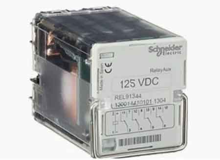
An auxiliary relay extends, isolates, or distributes control signals generated elsewhere. Protective relays sense abnormal conditions and decide when action is required, but they carry that decision into the real world by operating trip coils, energizing alarms, or coordinating multiple outputs from a single command. In ANSI and IEEE terminology, auxiliary and lockout relays are often associated with device 86, particularly where fault conditions require manual reset before re-energization.
The practical difference becomes obvious in complex installations. A single protective relay output may need to trip several breakers, initiate annunciation, and send status feedback to SCADA. Without them, that single output would be overloaded, unreliable, or electrically unsafe. This is why auxiliary relays are foundational to broader protection architectures such as those described in the power system protection framework.
Because auxiliary relays sit between logic and action, they are often the first point at which small design choices have large operational consequences. Contact ratings that look acceptable on paper may degrade rapidly when repeatedly driving trip coils. Coil-voltage mismatches in control power systems introduce nuisance behavior that is hard to diagnose. Even contact arrangement decisions can determine whether a fault clears cleanly or leaves a system in an unsafe intermediate state.
Think you know Electrical Protection? Take our quick, interactive quiz and test your knowledge in minutes.
This is especially critical in installations where coordination matters, such as breaker schemes described in relay and circuit breaker coordination. The relay that operates too slowly, sticks mechanically, or bounces contacts can undermine an otherwise well-designed protection study.
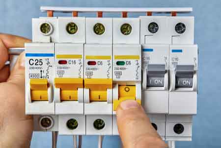
Auxiliary relays are often grouped by function, but those categories exist because each design solves a specific coordination problem. Instantaneous relays are selected when any delay would be unacceptable, such as emergency tripping or alarm initiation. Time-delay versions introduce intentional sequencing to avoid nuisance operations or to stage responses during motor starts or system restoration.
Latching relays play a different role. In lockout schemes, they preserve fault state information until an operator intervenes, preventing automatic reclosing into an unresolved condition. Interposing relays appear simple, but their value lies in electrical isolation, especially when interfacing modern electronic relays with legacy control wiring or PLC logic. These distinctions become increasingly important as systems evolve away from purely electromechanical designs toward mixed architectures that incorporate protective relays and digital logic.
Experienced engineers tend to look past datasheet summaries and focus on behavior under stress. Coil burden affects how control power systems respond during voltage dips. Contact material influences long-term reliability in trip circuits. Mechanical life ratings matter less than electrical life when contacts repeatedly interrupt inductive loads.
Environmental resilience is another differentiator. Relays installed in substations, motor control centers, or metal-enclosed assemblies such as metal-clad switchgear are subject to vibration, temperature swings, and contamination that office-grade components simply are not designed to withstand.
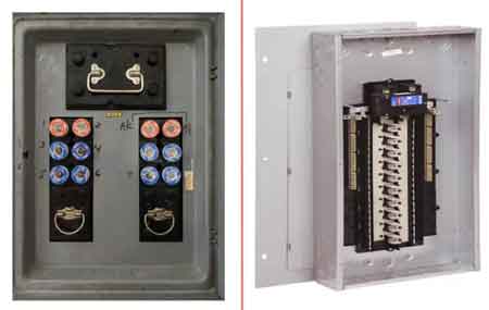
In substations, auxiliary relays distribute trip signals from a single protection element to multiple breakers, coordinate alarms, and provide clear fault indication. In industrial facilities, they support motor interlocks, safety circuits, and shutdown sequencing, often working alongside systems dedicated to electric motor protection.
One common scenario involves transformer protection. A differential relay detects an internal fault and issues a trip command. They ensure that the command opens all relevant breakers, activates alarms, and blocks re-energization until the condition is investigated, reinforcing the intent behind transformer protection strategies.
Most auxiliary relay failures traced in the field are not component defects but wiring or application errors. Incorrect polarity on DC coils, misidentified normally open and normally closed contacts, or inadequate labeling can turn routine maintenance into extended outages. Good practice includes clear terminal identification, consistent panel documentation, and verification testing before commissioning.
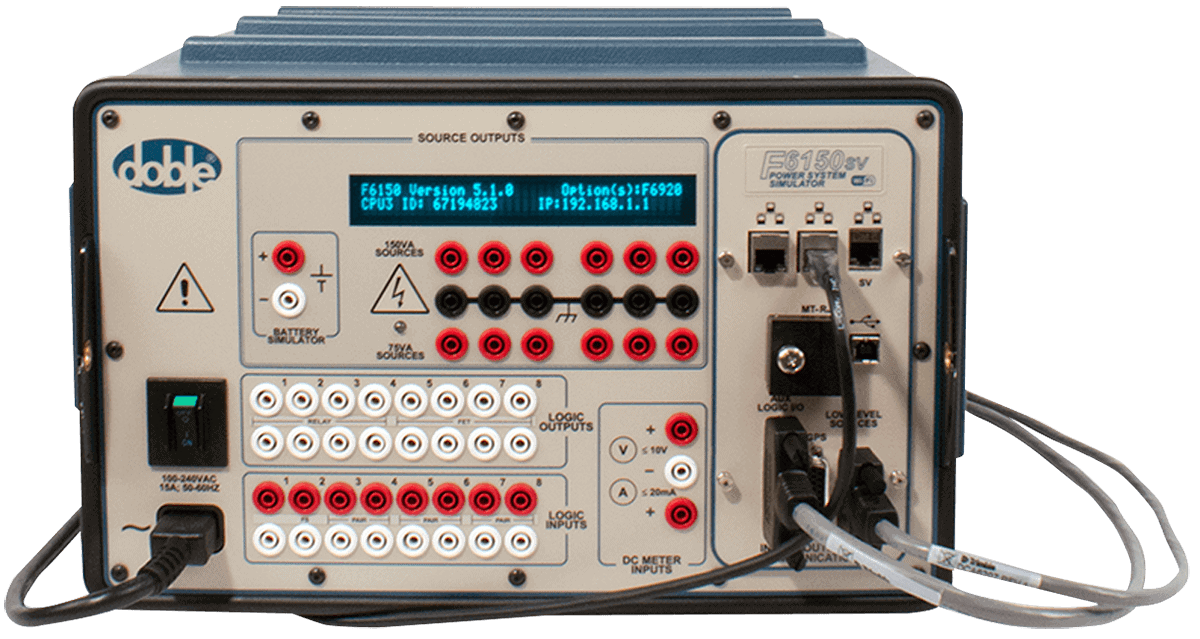
Testing should confirm not only continuity but also correct operation under simulated fault conditions. This is particularly important when they interact with electronic devices, including those discussed in how does a solid state relay work, where behavior differs from traditional electromechanical designs.
Auxiliary relays fail quietly. Contacts wear, weld, or develop resistance. Coils overheat or open. Environmental contamination accelerates degradation. When these failures occur, they often masquerade as protection logic errors rather than hardware issues, complicating diagnosis.
Understanding these risks influences whether designers choose traditional relays, solid-state alternatives, or redundant configurations. It also reinforces why auxiliary devices belong within the broader context of what is electrical protection, not as isolated components.
Protective relays decide when a system must trip. Auxiliary relays determine whether that decision is carried out cleanly across every breaker, alarm, and interlock involved. They do not sense faults themselves, but they provide the contact capacity, electrical isolation, and signal routing needed to translate a protective decision into coordinated action.
Download our FREE Electrical Training Catalog and explore a full range of expert-led electrical training courses.

This difference matters when systems fail. A poorly applied protective relay may cause nuisance operations, but a poorly applied auxiliary relay can prevent a trip from reaching its destination, leaving equipment energized when it should not be. In complex schemes, especially those involving lockout or multi-breaker tripping, auxiliary relays often decide whether a fault is fully contained or only partially cleared.
• Relay and Circuit Breaker Coordination
Advantages To Instructor-Led Training – Instructor-Led Course, Customized Training, Multiple Locations, Economical, CEU Credits, Course Discounts.
Request For QuotationWhether you would prefer Live Online or In-Person instruction, our electrical training courses can be tailored to meet your company's specific requirements and delivered to your employees in one location or at various locations.