Delta vs Wye Explained
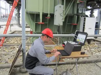
Substation Maintenance Training
Our customized live online or in‑person group training can be delivered to your staff at your location.
- Live Online
- 12 hours Instructor-led
- Group Training Available
Download Our NFPA 70E Fact Sheet – 2024 Electrical Safety Edition
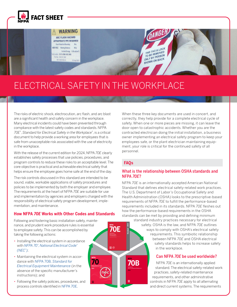
- Understand how NFPA 70E works with NEC and NFPA 70B standards
- Clarify the shared responsibility between employers and employees
- Learn how NFPA 70E supports OSHA compliance
Delta vs Wye transformer connections compare line-to-line and line-to-neutral wiring. Each impacts voltage, current, fault tolerance, and power distribution efficiency in electrical systems. Knowing both ensures safe and reliable design.
What is Delta vs Wye?
Delta vs. Wye configurations are fundamental to understanding three-phase power systems, which form the backbone of electricity distribution in industrial, commercial, and institutional settings.
✅ Delta uses line-to-line connections for higher voltage handling
✅ Wye offers line-to-neutral grounding for stability and safety
✅ Choice impacts efficiency, fault protection, and load balancing
These configurations, named after their visual resemblance to the Greek letter delta (Δ) and the letter Y, dictate how the three phases are interconnected and how voltage and current are distributed within the system. For electrical professionals working in these sectors, a solid understanding of the Delta vs. Wye concept is essential for ensuring efficient power utilization, selecting suitable equipment, and maintaining a safe and reliable electrical infrastructure. This article provides a comprehensive overview of both configurations, examining their unique characteristics, advantages, disadvantages, and real-world applications to equip professionals with the knowledge necessary to make informed decisions regarding their electrical systems. To understand how Delta vs Wye fits into the broader landscape, see our guide on electrical transformers and their role in power distribution systems.
Electrical Transformer Maintenance Training
Substation Maintenance Training
Request a Free Training Quotation
When studying the Delta system, electrical professionals must consider how line-to-line voltage behaves at high voltages and how currents may be phase shifted compared to single-phase power. These concepts are crucial for understanding why Delta vs. Wye connections are selected in various applications. Just as a date browser may not display this or other websites correctly unless you upgrade or use an alternative browser, outdated knowledge of transformer configurations can lead to errors in design and safety.
FREE EF Electrical Training Catalog
Download our FREE Electrical Training Catalog and explore a full range of expert-led electrical training courses.

- Live online and in-person courses available
- Real-time instruction with Q&A from industry experts
- Flexible scheduling for your convenience
Delta vs Wye Connection Comparison Table
| Feature | Delta Connection (Δ) | Wye Connection (Y) |
|---|---|---|
| Configuration | Closed triangle | Star shape with a central neutral point |
| Voltage | Line voltage = Phase voltage | Line voltage = √3 × Phase voltage |
| Neutral Availability | No neutral wire | Neutral wire available |
| Applications | High-power transmission, motors | Distribution systems, balanced loads |
| Efficiency | Suitable for heavy loads | Better for varied loads with neutral grounding |
| Fault Protection | Less safe due to no neutral path | Safer due to grounded neutral |
| Cost | Often more cost-effective for power transmission | May require additional insulation and grounding |
Current flow differs between Delta and Wye systems, making it helpful to review the function of a current transformer in monitoring and measuring line current.
Three-Phase Power
Three-phase power systems are the backbone of modern electricity distribution. Unlike single pahse power, which uses one conductor and a neutral, three-phase systems utilize three conductors carrying alternating currents that are 120 degrees out of phase with each other. This arrangement enables more efficient power transmission and smoother motor operation compared to single-phase systems. Delta and Wye configurations determine how these three phases are interconnected within devices such as generators, transformers, and motors.
Star Connection
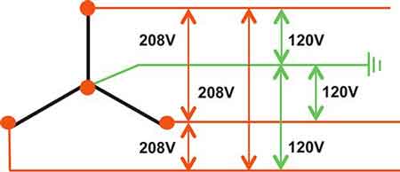
The Wye connection, also known as the star connection, gets its name from its visual resemblance to the letter Y or a star. In this configuration, one end of each of the three windings is connected to a common point, known as the neutral point. The other ends of the windings connect to the three-phase lines. This configuration is commonly used in low-voltage distribution systems, allowing for both line-to-line and line-to-neutral voltages, which provides flexibility in supplying different types of loads.
Line Voltage
Line voltage refers to the electrical potential difference between any two of the three line conductors in a three-phase system. It represents the voltage across the 'external' part of the circuit, the part that transmits power between different components. In a Delta connection, line voltage and phase voltage are equal. However, in a Wye connection, line voltage is higher than phase voltage by a factor of the square root of 3 (approximately 1.73). For environments requiring fire safety and reduced maintenance, engineers often compare Delta and Wye connections with dry-type transformers.
Phase Voltage
Phase voltage is the voltage measured across a single winding in a three-phase system. It represents the voltage 'internal' to the device, across the individual components that make up the load or source. In a Wye connection, the phase voltage is the voltage between any line and the neutral point. Understanding the distinction between line and phase voltage is crucial for selecting and operating electrical equipment correctly. In low-voltage applications, choosing between Delta and Wye configurations may also involve specialized designs, such as a control transformer, which provides a stable voltage for sensitive equipment.
Line Current
Line current is the current flowing through any of the three line conductors. It represents the current that is carried by the transmission lines and delivered to the load. In a Wye connection, the line current is equal to the phase current. However, in a Delta connection, line current is higher than phase current by a factor of the square root of 3.
Phase Current
Phase current is the current flowing through a single winding of the three-phase load or source. In a Delta connection, phase current is the current flowing through each individual winding of the load. The relationship between line and phase currents is determined by the specific configuration (Delta or Wye) and is important for sizing conductors and protective devices.
Power Factor
Power factor is a critical concept in AC circuits, representing the ratio of real power (the power actually used to do work) to apparent power (the total power supplied to the circuit). It indicates how effectively electrical power is being used. Both Delta and Wye connected systems can have power factor considerations, and optimizing power factor is essential for efficient energy use and minimizing losses. Whether applying Delta or Wye, professionals must size equipment correctly. Resources like our transformer sizing and transformer testing pages provide practical guidance.
Sign Up for Electricity Forum’s Electrical Transformers Newsletter
Stay informed with our FREE Electrical Transformers Newsletter — get the latest news, breakthrough technologies, and expert insights, delivered straight to your inbox.
Applications
Delta and Wye connections find applications in various electrical systems. Delta connections are often preferred in high-power applications, such as industrial motors and generators, due to their ability to handle higher currents. Wye connections, with their neutral point, are common in low-voltage distribution systems, allowing for single-phase loads to be connected alongside three-phase loads. The choice between Delta and Wye also affects efficiency, making topics such as transformer losses and transformer ratings critical to system performance.
Advantages and Disadvantages
Each configuration has its own set of advantages and disadvantages. Delta connections offer higher reliability in the event of a phase failure and are generally more efficient for high-power loads. Wye connections provide the flexibility of both line-to-line and line-to-neutral voltages, but they are more susceptible to voltage imbalances. Choosing the right configuration depends on the specific application requirements.
Transformation
Delta-Wye and Wye-Delta transformations are mathematical techniques used to simplify the analysis of complex three-phase circuits. They allow engineers to convert between the two configurations, making it easier to calculate voltages, currents, and power in the system. These transformations are also utilized in practical applications, such as motor starting, where a Wye-Delta starter reduces the motor's starting current.
When utilizing AC power in a three-phase system, the Delta configuration offers a unique approach to connecting the source and load. In a Delta configuration, the three windings are connected end-to-end, forming a closed loop that resembles the Greek letter delta (Δ). This arrangement results in the phase-to-phase voltage being equal to the line voltage, which can be advantageous in high-power applications. However, it's essential to note that the Delta configuration lacks a neutral point, which can limit its application in systems that require both line-to-line and line-to-neutral voltages.


