What is Low Voltage?

By R.W. Hurst, Editor


Low voltage refers to electrical systems operating at 50 to 1000 volts AC or 120 to 1500 volts DC. Common in residential, commercial, and control circuits, it reduces shock risks while powering lighting, HVAC, security systems, and automation equipment safely.


What is Low Voltage?

Low voltage is a range of electrical power levels below high-voltage thresholds.

✅ Reduces risk of electrical shock in residential and commercial settings

✅ Powers lighting, security, HVAC, and control systems

✅ Common in telecommunications and automation applications


In today's technologically driven world, understanding the concept of low voltage (LV) is essential. Low voltage systems are widely used across industries, homes, and offices, making them an integral part of our daily lives. This article provides an overview of LV, its applications, safety measures, and regulations, incorporating the keywords provided. Low voltage systems are designed to operate below 600 volts, unlike high voltage systems that present increased shock hazards.

The low voltage definition is relatively simple: Any electrical system or equipment operating at a voltage level less than or equal to 600 volts. LV systems in the United States are generally categorized as those working between 50 and 600 volts. These systems are utilized in various applications due to their low power consumption and reduced risk of electric shock. Understanding the concept of voltage is essential when working with residential or industrial low voltage wiring.


Applications

Low voltage applications are diverse and include control rooms, distribution systems, lighting, communication systems, and security systems. LV wiring is often used in these applications, as it is designed for smaller currents and offers increased safety compared to regular wiring. This wiring type is also more cost-effective and easier to install. Voltage drop can significantly impact the performance of low voltage circuits, especially over long wiring runs.

Regarding LV safety, it is crucial to take necessary precautions as even LV electrical equipment can pose risks. For example, to minimize the chance of electric shock, one should always turn off the power supply before working on any electrical equipment and use insulated tools. Additionally, it is essential to adhere to local LV regulations and standards to ensure a safe working environment.


Devices

Low voltage devices are found in various settings, from residential to commercial and industrial. Some examples of low voltage devices include thermostats, doorbells, intercom systems, and landscape lighting. These devices usually require transformers to convert the higher voltage from the main power supply to a lower voltage suitable for operation.

Regulations and standards for LV installations vary by country and region. However, the National Electrical Code (NEC) provides guidelines and requirements for LV installations to ensure safety and reliability in the United States. Professionals working with low voltage systems must adhere to these guidelines and any additional local regulations.

Low voltage transformers and power supplies are critical in distributing low voltage electricity. Transformers are used to step down higher voltages from the main power supply to the required LV level. In contrast, power supplies regulate and distribute electrical energy to various devices. Low voltage distribution systems are designed to efficiently deliver electricity to low voltage equipment while maintaining safety and reliability.


Systems

While low voltage systems are generally safer than high voltage electrical systems, they still require proper handling and adherence to safety measures. High-voltage transmission systems are used to transport electricity over long distances from power plants to substations. High voltages range from 100 kV to 765 kV, while ultra-high voltages can reach above 800 kV. Large industrial facilities, such as factories that use medium-voltage systems, typically operate between 1 kV and 35 kV.

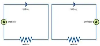
Understanding LV is crucial today, as these systems are widely used in various applications. With proper installation, adherence to regulations, and safety precautions, LV systems can provide numerous devices with an efficient and reliable power supply. As a result, low voltage systems play an essential role in our daily lives, whether for lighting, communication, or security. Key electrical components such as resistors and capacitors are frequently used in low voltage control systems.


Frequently Asked Questions


Is "low voltage" defined differently in 110V systems and 220V systems?

While the term "low voltage" describes electrical systems operating at a voltage level lower than a certain threshold, the specific voltage ranges considered low voltage can vary slightly between countries and regions due to differences in their electrical distribution systems. However, the general concept remains the same across 110V systems in North America and 220V systems in the EU. For efficient power distribution, low voltage systems rely on solid grounding practices, making ground faults and electrical faults important safety considerations.

In North America, low voltage typically refers to electrical systems operating between 50 and 600 volts. In contrast, in the EU, the term "LV" is defined by the Low Voltage Directive (LVD), which covers electrical equipment designed for use with a voltage rating of 50 to 1000 volts for alternating current (AC) and 75 to 1500 volts for direct current (DC).

Despite these minor differences in the defined voltage ranges, the reasons behind the classification of LV systems remain consistent. LV systems are generally considered safer than their high voltage counterparts, as the risk of electric shock is lower. Additionally, they consume less power, making them more energy-efficient and cost-effective for certain applications.

The main factor causing the difference in voltage levels between regions is the choice of electrical distribution systems. For example, 110-120V systems are more common in North America, while in Europe and many other parts of the world, 220-240V systems are standard. This difference is primarily due to historical reasons and the evolution of each region's electrical infrastructure over time.

Regardless of these regional differences in voltage levels, the fundamental principles and safety considerations for LV systems remain largely the same. Both 110V and 220V systems use LV electrical equipment and wiring to provide power for various applications while adhering to regional safety standards and regulations to ensure these systems' safe and efficient operation. The behavior of current in low voltage applications is best understood by applying Ohm’s Law, which explains the relationship between voltage, current, and resistance.


What are examples of low voltage systems?

Low voltage systems are widely used in various residential, commercial, and industrial applications due to their increased safety and energy efficiency. Here are some examples of LV systems:

Lighting systems: Low voltage lighting, such as LED lights and halogen lamps, is commonly used for residential and commercial purposes, including landscape lighting, recessed lighting, and track lighting. These systems often use transformers to step down the voltage from the main power supply to a suitable level for the lights.

Security systems: LV is used in security systems, including alarm systems, access control systems, and surveillance cameras. These systems require a stable and reliable power source with minimal risk of electrical hazards.

Communication systems: LV wiring is utilized in various communication systems, including intercoms, telephone lines, and data networks. It enables the reliable transmission of data and voice signals while minimizing energy consumption and interference.

Audio and video systems: LV components are used in home theatre systems, speakers, and AV equipment. The low voltage wiring ensures minimal signal loss and interference for better audio and video quality.

HVAC controls: Thermostats, sensors, and control panels for heating, ventilation, and air conditioning systems often use low voltage wiring and components to maintain efficient energy use and reliable control of the HVAC system.

Doorbells and chimes: LV systems are commonly used in doorbells and chime systems to ensure safe and reliable operation.

Fire alarm systems utilize LV wiring and components to provide a reliable means of detecting and responding to potential fire hazards while minimizing the risk of electrical hazards.

Home automation systems often utilize LV for controlling and automating various devices, including lighting, appliances, and security systems. This allows for the energy-efficient and safe operation of connected devices.

Solar power systems: In small-scale solar power installations, LV DC systems are used to store and distribute the electricity generated by solar panels. These systems typically include charge controllers, batteries, and inverters to efficiently manage the power supply.

Industrial control systems: LV is used in various industrial applications to control and monitor machinery and equipment. This includes programmable logic controllers (PLCs), motor controls, and sensor networks, which require stable and reliable power sources with minimal risk of electrical hazards. Devices like multimeters and voltmeters are essential tools for testing and maintaining low voltage installations.


Related Articles


Related News

What is a Busbar?

A busbar is a metallic strip or bar used in electrical systems to conduct electricity within switchgear, distribution panels, and substations. It distributes power efficiently and reduces resistance, enhancing safety and electrical performance.


What is a Busbar?

A busbar is a crucial electrical component used to conduct, distribute, and manage power in electrical systems. Found in commercial, industrial, and utility applications, it helps centralize connections and minimize wiring complexity.

✅ Provides efficient power distribution in electrical panels and substations

✅ Reduces resistance and improves system reliability

✅ Supports compact, organized electrical design for switchgear and distribution boards

A Busbar is an important component of electrical distribution systems, providing a central location for power to be distributed to multiple devices. It is an electrical conductor responsible for collecting electrical power from incoming feeders and distributing it to outgoing feeders. They are made of metal bars or metallic strips and have a large surface area to handle high currents.

How Does it Work?

It is a strip or bar made of copper, aluminum, or another conductive metal used to distribute electrical power in electrical systems. They have a large surface area to handle high currents, which reduces the current density and minimizes losses. They can be insulated or non-insulated, and they can be supported on insulators or wrapped in insulation. They are protected from accidental contact by either a metal earthed enclosure or elevation out of normal reach.

They collect electrical power from incoming feeders and distribute it to outgoing feeders. The bus bar system provides a common electrical junction for various types of electrical equipment, designed to handle high currents with minimal losses. They are often used in industrial applications, where they are installed in electrical panels or switchgear panels.


Different Types of Busbars

Different types of busbars are available on the market, including those made of copper or aluminum, as well as insulated or non-insulated, and segmented or solid busbars. Copper or brass busbars are used in low-voltage applications, while aluminum busbars are used in high-voltage applications. Insulated busbars are used in situations where accidental contact can occur, and segmented busbars are used to connect different types of equipment.

Busbars can also be classified based on their cross-section. A rectangular is the most common type and is often used in low-voltage applications. On the other hand, a tubular busbar is a hollow cylinder used in high-voltage applications. Finally, a circular one has a circular cross-section and is used in high-current applications.


Busbar Types and Characteristics

Attribute Copper Busbar Aluminum Busbar Laminated Busbar
Conductivity Excellent (≈100% IACS) Good (≈61% IACS) Varies (depends on internal conductor materials)
Weight Heavy Lightweight Moderate
Cost Higher Lower Higher (due to fabrication complexity)
Heat Dissipation Excellent Good Excellent (designed to reduce hot spots)
Applications Switchgear, substations, panels Bus ducts, high-rise buildings Compact power modules, UPS, power electronics
Mechanical Strength High Moderate Moderate to High
Corrosion Resistance High (especially tinned copper) Requires anodizing/coating Depends on encapsulation
Ease of Fabrication Good Excellent Complex


The Purpose of a Busbar in an Electrical System

The primary purpose of an electrical system is to distribute electrical power to different parts of the system. The busbar system collects electrical power from incoming feeders and distributes it to outgoing feeders. Busbars also provide a common electrical junction for different types of electrical equipment.


Busbar and Circuit Breakers

They are often used in conjunction with circuit breakers. Circuit breakers protect electrical circuits from damage caused by overload or short circuits. Additionally, they can be used to isolate the electrical supply in the event of a fault or overload. Circuit breakers are often installed in electrical or switchgear panels, which can be easily accessed and maintained.


Busbars and Electrical Distribution Equipment

They are an essential component of electrical distribution equipment, including electrical panels, switchgear panels, and distribution boards. Electrical panels distribute power to various parts of a building, while switchgear panels control the flow of electrical power in industrial applications. Distribution boards divide the electrical supply into separate circuits at a single location.


Busbar Installation

Installing a busbar involves several basic steps. First, the busbar system's design must be created, considering both the electrical load and the required current-carrying capacity. Then, it is installed in the electrical panel or switchgear panel. Finally, it is connected to the electrical equipment using either bolts, clamps, or welding.


Maintenance

Maintaining a busbar system involves regular inspections and cleaning. The system should be inspected for any damage or corrosion, and the connections should be tightened if they become loose. Regular cleaning of the system is also essential to prevent the buildup of dust or dirt, which can lead to a short circuit.


Safety Precautions

Working with busbars involves high voltage and current, so taking proper safety precautions is essential. The system must be isolated from the electrical system before any maintenance is performed. Personal protective equipment, such as gloves and safety glasses, should be worn while working with busbars. Working on a live system should only be done by trained personnel after ensuring that all necessary safety precautions are in place.


Accidents involving Busbars

Accidents can occur when working with busbars, and they can be dangerous if proper safety precautions are not taken. One common accident that can occur involves accidental contact with a live one. This can cause electrical shock, burns, and even death. Another accident involves short circuits, which can lead to equipment damage, fire, or explosions. These accidents can be prevented by following proper safety procedures and wearing personal protective equipment.

Arc flash accidents, including busbars, are a potential hazard when working with electrical equipment. An arc flash is an electrical explosion that can occur when a fault occurs in an electrical circuit, resulting in a short circuit or electrical discharge. Arc flash accidents can cause severe burns, hearing loss, and even death.

They can be a source of arc flash accidents if proper safety precautions are not taken. For example, if a live busbar comes into contact with an object, it can cause an arc flash. Proper insulation and guarding are necessary to prevent arc flash accidents involving busbars. They should also be installed in a way that minimizes the possibility of accidental contact.

Additionally, they should be designed to handle the expected current load, as overloading can lead to a fault and an arc flash. It is also essential to follow proper maintenance procedures, including regular system inspections and cleaning, to prevent damage or corrosion that can cause faults and arc flashes.

Overall, busbars are related to arc flash accidents as they can be a source of electrical faults that can lead to an arc flash. Therefore, following proper safety procedures, including proper insulation, guarding, and system maintenance, is crucial to prevent arc flash accidents.


Related Articles


View more

What is Current Electricity?

Current electricity is the flow of electric charge through a conductor, usually as moving electrons. It powers devices in homes and industries. Driven by voltage, this flow enables the transfer of energy through wires, forming the basis of modern electrical systems.


What is Current Electricity?

Current electricity refers to the continuous movement of electric charges (typically electrons) through a conductor, driven by an electromotive force (EMF), or voltage.

✅ Describes the movement of electric charge through a conductor

✅ Powers electrical devices in homes, industries, and electronics

✅ Exists as direct current (DC) or alternating current (AC)

Current is defined as an electrical charge in motion. It consists of a flow of negatively charged electrons from atom to atom through a conductor in an electrical circuit. The external force that causes the electron current flow of electric charge is called the electromotive force (emf) or voltage.

When charges move through these wires, they generate different forms of energy, which can power devices and systems. One common type of current is alternating current (AC), where the direction of the charge flow periodically reverses. This movement of charges can be compared to water flowing through a pipe, where the electrical potential pushes the flow, making it essential for transporting energy efficiently across distances.


The Quantitative Definition

Electric current is defined as the rate of flow of electric charge:

I = Q / t

Where:

  • I is current in amperes (A)

  • Q is charge in coulombs (C)

  • t is time in seconds (s)

For example, a current of 1 ampere means 1 coulomb of charge flows per second through a given point in the circuit.


Types of Current: AC and DC

  • Direct Current (DC): Charge flows in one constant direction. Example: Batteries.

  • Alternating Current (AC): Charge reverses direction periodically. Example: Household wall outlets (typically 60 Hz in North America).


How Current Electricity Works

Electric current arises when free electrons move through a conductor. In metals, these electrons are loosely bound and can drift when a voltage is applied. This movement is like water flowing through a pipe — voltage acts as the pressure that pushes the electrons along.

Voltage sources such as batteries or generators create this pressure, known as electromotive force (emf). The electrons flow from the negative terminal (excess electrons) toward the positive terminal (electron deficiency).


Effects of Electric Current

Electric current produces multiple observable effects:

  • Magnetic effect: Current creates magnetic fields (used in motors and transformers).

  • Thermal effect: Electric current generates heat (used in heaters and toasters).

  • Chemical effect: In electrolysis, current causes chemical reactions.

These effects make current electricity essential for thousands of real-world applications.


Ohm’s Law and Resistance

Ohm’s Law defines the relationship between voltage (V), current (I), and resistance (R):

V = I × R

Where:

  • V is voltage in volts

  • I is current in amperes

  • R is resistance in ohms (Ω)

This relationship helps calculate circuit behavior and select the right components for safe and effective electrical design.


Measuring Current

Current is measured using devices such as:

  • Ammeter: Installed in series with a circuit to measure current directly.

  • Clamp meter: Measures current without disconnecting wires, using magnetic field sensing.

  • Multimeter: A general-purpose tool that can measure voltage, resistance, and current.


Real-World Applications

Current electricity is present in virtually every aspect of modern life:

  • Lighting systems

  • Household appliances

  • Industrial machinery

  • Electric vehicles

  • Cell phones and computers

  • Medical equipment

  • Power grids and transmission lines

It also flows in biological systems, such as ion currents in nerve cells and plasma currents in scientific and industrial applications.


Static vs. Current Electricity

Although both involve electric charges, static electricity refers to charges at rest, whereas current electricity refers to the motion of those charges. Static electricity may build up and discharge suddenly, but only current electricity performs continuous work, such as powering a device or generating heat.


Frequently Asked Questions


What is an example?

Examples of current electricity are starting a car, turning on a light, cooking on an electric stove, watching TV, shaving with an electric razor, playing video games, using a phone, charging a cell phone and more. 


Is current and electricity the same?

Current is a general characteristic of alternating current AC, like voltage and resistance. It's a name given to the flow of electrons (charge) through a medium. Electricity is a generic term used to describe the common flow of energy that powers all electrical devices. Current, in general, refers to any flow.


What are the two types of current electricity?

There are two different types of current in widespread use today. They are direct current, abbreviated DC, and alternating current, which is abbreviated AC. In a direct current, the electrons flow in one direction.

The electromotive force (emf) or voltage, as explained by Ohm's law, is created by a battery that consists of one positively charged and one negatively charged terminal. The negative terminal has an excess of electrons, while the positive terminal has a deficiency of electrons. When a conductor, in this case an electric light bulb, is connected to the two terminals of the battery, a flow of electrons occurs, producing both magnetic fields and an electric field. The positive terminal of the battery has a shortage of electrons and thus attracts electrons from the conductor. The negative terminal has an excess of free electrons to move, which repels electrons into the conductor.

Although "static" and "current" may seem different, they are really the same—both consist of electrical charges. Static electricity consists of electrons at rest on an insulated object and does little work. CE charge flows and does useful work. When static electricity is discharged, it is no longer static electricity — it is actually current electricity.

CE may also be classified as either direct current (DC) or alternating current (AC) based on the voltage source. Direct current voltage produces a constant flow of electrons in one direction only. Alternating current voltage produces a flow of positive and negative charge electrons in both directions, with varying magnitude. A battery is a common DC voltage source, while an electrical wall outlet is the most common AC voltage source (Figure 1).

Polarity identification (+ or -) and magnetic fields are one way to distinguish between a voltage source and a current source. Polarity can be identified on direct current circuits, but in alternating current circuits, the current continuously reverses direction; therefore, polarity cannot be identified. Additionally, it is essential to determine whether an electrical energy source generates alternating current or direct current. Many control and load components are designed to operate with a specific type of current. Operating the components with the wrong type of current or DC polarity can result in improper operation and/or permanent damage to the component.


Fig. 1. Current Electricity. Electrical charges moves.


Related Articles


View more

What do Ammeters Measure?

An ammeter measures electric current in a circuit, displayed in amperes (A). Connected in series with low internal resistance to reduce burden voltage, it ensures accurate readings for testing, fault detection, and diagnostics.


What do Ammeters Measure?

Ammeters are measuring devices that measure the flow of electricity in the form of current in a circuit.

✅ Measure electric current in amperes, connected in series with low internal resistance to minimize burden voltage.

✅ Available in analog, digital, clamp, and current transformer designs.

✅ Used for testing, fault detection, continuity checks, and diagnostics.

Electrical currents are then measured in the form of amperes, hence the name "ammeter". The term "ammeter" is sometimes used incorrectly as "ampmeter". Understanding how an ammeter works is easier when you first explore the basics of electricity fundamentals, including how voltage, current, and resistance interact in a circuit.

An ammeter measures electric current in a circuit, expressed in amperes (A). It must be connected in series with the load so that all the current flows through it, and is designed with low internal resistance to minimize burden voltage, thereby ensuring accurate readings without significantly affecting the circuit’s performance. The measurement unit for an ammeter is the ampere, explained in detail on our what is an ampere page, which also covers its relationship to other electrical units.

Ammeters are designed (as well as ohmmeters and voltmeters) to be used with a sensitive current detector such as a moving coil in a galvanometer. To measure the electric current flow through it, an ammeter is placed in series with a circuit element. The ammeter is designed to offer very low resistance to the current, so that it does not appreciably change the circuit it is measuring. To do this, a small resistor is placed in parallel with the galvanometer to shunt most of the current around the galvanometer. Its value is chosen so that when the design current flows through the meter, it will deflect to its full-scale reading. A galvanometer's full-scale current is very small: on the order of milliamperes. To see how ammeters fit into broader measurement tools, check out our guide on what is a voltmeter and what is a multimeter, which measure multiple electrical properties.

An Ammeter is analog. It is not mechanical or digital. It uses an analog-to-digital converter (ADC) to measure the voltage across the shunt resistor. The ADC is read by a microcomputer that performs the calculations to display the current through the resistor.


How an Ammeter Works

An ammeter works by being placed in series with the circuit so that all the current flows through it. Inside, a shunt resistor with very low internal resistance creates a small, measurable voltage drop proportional to the current. In analog designs, this current is partly diverted around a sensitive moving-coil mechanism, which displays the reading on a scale. In digital designs, the voltage drop across the shunt is measured by an analog-to-digital converter (ADC) and calculated into an amperes value, ensuring accurate measurement without significantly disturbing the circuit’s performance. Accurate current measurement also depends on understanding what is electrical resistance and how it affects current flow, especially in low-resistance ammeter designs.


Types and Mechanisms

Analog ammeter – Includes moving-coil (D'Arsonval) and moving-iron types, which use magnetic deflection to display current on a scale. These designs are valued for their simplicity, durability, and ability to provide continuous current readings.

Digital ammeter – Uses a shunt resistor to create a small voltage drop proportional to the current. This voltage is measured by an analog-to-digital converter (ADC) and displayed as a precise digital value. Digital ammeters often feature higher accuracy, wider measurement ranges, and additional functions such as data logging.

Clamp meter – Measures current without breaking the circuit by detecting the magnetic field around a conductor. This method is ideal for quick testing, especially in high-current applications or where live connections cannot be interrupted.

Current transformer (CT) ammeter – Designed for high-current AC systems, this type uses a transformer to scale down large primary currents into a safe, measurable secondary current for the meter.


Shunts and Operation

A shunt resistor is a precision, low-resistance component used in many ammeters. In analog designs, it is placed in parallel with the meter movement, diverting most of the current to protect the instrument. In certain digital designs, it is placed in series with the circuit. By measuring the voltage drop across the shunt and applying Ohm’s law, the meter accurately calculates the current. This approach allows for measurement of very large currents without damaging the meter and helps maintain measurement stability.


Applications and Value

Ammeters are essential tools in electrical testing, short-circuit detection, continuity testing, and system diagnostics. They help identify overloads, open circuits, and unstable current conditions that may indicate equipment faults or inefficiencies.

In industrial, commercial, and residential settings, ammeters are used for equipment maintenance, troubleshooting, and performance monitoring. Specialized variants such as milliammeters and microammeters are designed for extremely low current measurements, while integrating ammeters track current over time to determine total electrical charge delivered to a device or system. For historical context on the development of measuring instruments, visit our history of electricity page to learn how electrical science evolved over time.


Practical Applications of Ammeters

Ammeters are used in a wide range of electrical and electronic work:

  • Automotive diagnostics – Measuring current draw from the battery to detect parasitic drains, starter motor issues, and charging system faults.

  • Solar panel and battery monitoring – Tracking current output from photovoltaic arrays and the charging/discharging rates of storage batteries to optimize system efficiency.

  • Industrial motor maintenance – Monitoring motor current to identify overload conditions, detect bearing wear, or confirm correct load operation.

  • Household appliance servicing – Checking current draw to troubleshoot faulty components or ensure devices operate within safe limits.

  • Power distribution systems – Ensuring current levels remain within capacity for cables, fuses, and protective devices.


Related Articles


View more

What is Electric Load

Electric load refers to the amount of electrical power consumed by devices in a system. It determines demand on the power supply and affects energy distribution, efficiency, and system design.


What is Electric Load?

✅ Measures the power consumed by electrical devices or systems

✅ Impacts system design, energy use, and load management

✅ Varies by time, usage patterns, and connected equipment

What is electric load? It refers to the total power demand placed on a circuit by connected devices. Electric load, such as lighting, motors, and appliances, impacts energy use, system sizing, and overall efficiency across residential, commercial, and industrial settings.

An electric load refers to any device or system that consumes electric power to perform work, such as an electric motor, lighting fixture, or household electrical appliances. These loads draw electrical energy from the power source, impacting both system efficiency and capacity planning. Accurate electrical load calculation is crucial for designing circuits, selecting the correct breakers, and ensuring safe operation in homes, businesses, and industrial facilities. Using real-time monitoring tools, engineers can assess load patterns, identify peak demand, and implement energy-saving strategies through smart load management systems.

An electric load can be anything that consumes power, such as lights, appliances, heating systems, motors, and computers. In electrical engineering, a load represents the demand that a device or installation places on the power source.

Electric load is closely influenced by regional consumption patterns, which can be explored in more detail in Electricity Demand in Canada, highlighting how climate and industry shape national power usage.

Different types of types exist, and they are classified based on their characteristics. Resistive loads include, for example, converting energy directly into heat, such as heaters or incandescent light bulbs. Inductive loads, however, require energy to create a magnetic field, such as motors or transformers. Capacitive loads, meanwhile, store and release energy, such as capacitors used in a powered circuit.


An electric load refers to any device or circuit that consumes energy in a system. A common example is a load that consists of appliances such as heaters or ovens, where the primary component is a heating element. This heating element converts energy into heat, providing warmth or cooking power. It consists of a heating mechanism that demands specific amounts of powered energy depending on the device’s power requirements, which is crucial for maintaining an efficient and balanced system. For readers new to electrical concepts, the Basic Electricity Handbook provides foundational knowledge that helps contextualize the meaning of electricity in power systems.


Types of Electrical Loads

Electric loads fall into three primary categories:

  • Resistive: Devices like incandescent light bulbs, heaters, and toasters. These convert energy directly into heat.

  • Inductive: Motors, transformers, and fans. Inductive loads create magnetic fields to operate, often resulting in a lagging power factor.

  • Capacitive: Capacitors are used in power factor correction equipment or some specialized electronic devices. They store energy temporarily.

Each load type interacts differently with the system, impacting both efficiency and stability.

Related: Understand how resistive loads behave in a circuit.


How to Calculate Electric Load

Accurately calculating electric load is important for selecting the correct wire size, circuit breakers, and transformer ratings.


For example:

  • If a device operates at 120 volts and draws 5 amps:

    • Load = 120 × 5 = 600 watts


Step-by-Step Example for a Household Circuit:

  1. Add up the wattage of all devices on the circuit.

  2. Divide the total wattage by the system voltage to find the total current load.

  3. Compare the load to the circuit breaker rating to ensure it is not overloaded.

Tip: Always design for 80% of breaker capacity for safety.


Why Understanding Electric Load Matters

Understanding electric load has real-world implications:

  • Energy Bills: Higher demand results in higher costs, particularly for businesses subject to demand charges.

  • System Design: Correct assessment ensures that wiring, transformers, and protection devices are appropriately sized.

  • Power Quality: Poor management can lead to low power factor, voltage drops, and even system instability.

  • Maintenance Planning: Predictable loads extend the life of equipment and reduce costly downtime.


Management Strategies

Smart load management can improve system efficiency and reduce costs:

  • Peak Shaving: Reducing consumption during periods of high demand.

  • Shifting: Moving heavy loads to off-peak hours.

  • Power Factor Correction: Installing capacitors to improve system efficiency and lower bills.


Electric load is a critical concept in both residential and industrial settings. By understanding the types of calculations used to determine total demand and the practical impacts on energy costs and system design, you can build safer, more efficient systems.

One critical aspect is the power factor. Power factor is the ratio of active power (measured in watts) to apparent power (measured in volt-amperes). In simpler terms, it is the efficiency of energy usage. A low power factor indicates that a device or system consumes energy more than necessary to perform a given task, leading to higher energy costs and increased strain on the power grid. The relationship between load, bill, and motor is especially evident in provincial models, such as Ontario’s Electricity Cost Allocation, which explains how peak demand affects consumer rates.

An electric load is a critical concept in the design and operation of the power grid. Understanding how it is measured, the different types, power factor, management strategies, peak, shedding, and demand response programs are essential for optimizing the use of the grid and ensuring its reliability. By balancing the demand for power with the grid's capacity, we can reduce energy costs, prevent blackouts, and create a more sustainable energy system. Management is a critical component of infrastructure planning, as discussed in the Transmission & Distribution Channel, which examines how levels affect grid design and performance.

In industrial environments, managing efficiently can lead to significant cost savings and operational stability. Explore these strategies in the Industrial Electric Power Channel.


View more

What is a Capacitor?

A capacitor is an electrical component that stores and releases energy in a circuit. It consists of two conductive plates separated by an insulator and is commonly used for filtering, power conditioning, and energy storage in electronic and electrical systems.


What is a Capacitor?

A capacitor is a key component in electronics and power systems. It temporarily stores electrical energy and is widely used in both AC and DC circuits.

✅ Stores and discharges electrical energy efficiently

✅ Used in filtering, timing, and power factor correction

✅ Found in electronics, motors, and power supplies

It is designed for energy storage and can store electric charges, which can be released when needed. In this article, we will delve into the fundamentals of capacitors, including their functions, types, and applications. To better understand how capacitors support overall system performance, explore our Power Quality overview covering the fundamentals of voltage stability and energy flow.

Power Quality Analysis Training

Power Factor Training

Request a Free Power Quality Training Quotation

A capacitor consists of two metallic plates separated by an insulating material known as the dielectric. The dielectric can be made from various materials, such as mica, paper, or ceramic. When voltage is applied across the plates, positive charges accumulate on one plate, while negative charges accumulate on the opposite plate. The amount of capacitor charge that can be stored depends on several factors, including plate area, plate separation, dielectric material, and voltage ratings. Capacitors are often used in capacitor banks to improve power factor and reduce energy losses in electrical systems.

How does a capacitor work? The primary function of a capacitor in an electronic circuit is to store electrical energy. Capacitors can be used for various purposes, such as filtering, timing, and coupling or decoupling signals. In addition, they play a crucial role in power supplies, ensuring that the output voltage remains stable even when there are fluctuations in the input voltage. Learn how capacitive loads influence circuit behavior and why they require precise capacitor selection for optimal performance.

A capacitor stores energy through the electrostatic field created between its plates. The stored energy can be calculated using the formula E = 0.5 * C * V^2, where E is the stored energy, C is the capacitance, and V is the voltage across the capacitor. Capacitance, measured in Farads, is a measure of a capacitor's ability to store charge. The capacitor voltage rating is crucial for ensuring safe operation and preventing dielectric breakdown during voltage spikes.

So, when I am asked what is a capacitor? I tell readers about several types of capacitors, each with unique applications. Common types include ceramic, electrolytic, film, and tantalum capacitors. Ceramic capacitors are widely used due to their low cost and small size. They are ideal for high-frequency applications and decoupling in power supply circuits. On the other hand, Electrolytic capacitors are popular for their high capacitance values and are commonly used in filtering and energy storage applications. Capacitors play a crucial role in power factor correction, enabling industrial systems to reduce demand charges and enhance energy efficiency.

Dielectric materials used in capacitors can be organic (such as paper) or inorganic (such as ceramic). The choice of dielectric material depends on factors like the desired capacitance value, voltage rating, and operating temperature range. Additionally, different dielectric materials exhibit varying properties, making them suitable for specific applications. For a deeper understanding of energy relationships, see how apparent power differs from real and reactive power in systems using capacitors.

A capacitor can be classified as polarized or non-polarized based on the presence or absence of polarity. Polarized capacitors, like electrolytic capacitors, have a positive and a negative terminal and must be connected correctly in a circuit to function properly. Non-polarized capacitors, like ceramic capacitors, do not have a specific polarity and can be connected in any orientation.

A Capacitor behaves differently in AC and DC voltage circuits. In DC circuits, once a capacitor is charged, it blocks the flow of current, essentially acting as an open circuit. However, in ac voltage circuits, capacitors allow the flow of alternating current. This phenomenon is known as displacement current, which occurs due to the continuous charging and discharging of charges.

So, what is a capacitor? Understanding what a capacitor is and how it works is essential for anyone interested in electronics. The Capacitor plays a vital role in a wide range of applications, from energy storage and filtering to signal coupling and decoupling. Understanding the various types of capacitors and their specific applications enables you to make informed decisions when designing or troubleshooting electronic circuits. Explore how an automatic power factor controller dynamically adjusts capacitor usage to maintain an efficient power factor in real-time.


Related Articles


View more

What is a Voltage Regulator?

What is a voltage regulator? A control circuit that stabilizes DC output from AC/DC power supplies using feedback, reference, and PWM; includes linear LDOs and switching buck/boost converters, improving line/load regulation, ripple suppression, efficiency.


What Is a Voltage Regulator?

It keeps voltage steady despite load changes, using linear or switching control to cut ripple, protecting circuits.

✅ Maintains setpoint via reference, error amplifier, feedback loop

✅ Linear LDOs offer low noise; dropout defined by headroom

✅ Switching buck/boost provide high efficiency, EMI needs filtering


What is a voltage regulator, and how does it work?

A voltage regulator is a component of the power supply unit that maintains a constant voltage supply through all operational conditions. Voltage regulators can regulate both AC and DC voltages, ensuring a steady, constant voltage supply. The output voltage is usually lower than the input voltage. The regulator compares the output voltage to a reference voltage and uses the difference to adjust the output voltage. An external voltage source or a circuit within the regulator typically sets the reference voltage. The regulator monitors the output voltage and adjusts it to maintain the reference voltage, which ensures a constant output voltage despite fluctuations in the input voltage or load conditions. For a succinct refresher on fundamentals, review what voltage is and how it is quantified in electrical systems.


Why is voltage regulation important in electronic circuits?

Voltage regulation is essential in electronic circuits because all electronic devices are designed to run at predetermined power ratings, including voltage and current. Therefore, the voltage supply should ideally be constant and steady for the device's proper functioning. Any variation in the voltage supply can lead to device malfunction or even failure. Voltage regulation ensures proper device operation and prevents damage due to voltage fluctuations. Design targets often align with a system's nominal voltage to ensure interoperability and safety margins.


What are the different types of voltage regulators?

They can be classified based on their physical design, active components used, and working principle. For example, linear and switching regulators are the most common classifications of active voltage regulators (that use amplifying components like transistors or op-amps).

Linear regulators use amplifying components like transistors or op-amps to regulate the output voltage. They are simple and reliable but less efficient as they waste excess power as heat. Linear regulators are suitable for low-power applications where efficiency is not a major concern. In many loads the effective behavior of a resistor network shapes the current draw and thermal budget.

Switching regulators, on the other hand, use inductors and capacitors to store and transfer energy, making them more efficient than linear regulators. They are commonly used in battery-powered devices as they consume less power. Switching regulators are more complex than linear regulators and require careful design and layout.

They can also be classified based on their physical design. Voltage regulators used in low-voltage electronic devices are usually integrated circuits. Power distribution centers providing AC power to residential and industrial consumers use more sophisticated and mechanically large voltage regulators that maintain a rated voltage regardless of consumption demands across the area. For context, consumer gadgets often operate within defined low-voltage categories that influence package choice and safety standards.


Can a voltage regulator be used for both AC and DC power sources?

Yes, they can be used for both AC and DC power sources. AC voltage regulators are used in power distribution centers to maintain a constant voltage supply to consumers. DC voltage regulators are used in electronic devices that run on DC power sources, such as batteries or DC power supplies. When selecting between sources, it helps to understand the difference between AC and DC and how each impacts regulation strategy.


What is the difference between a voltage regulator and a voltage stabilizer?

Linear voltage regulators and voltage stabilizers are similar in function as they both regulate the output voltage. However, the main difference between the two is in their working principle. They maintain a constant output voltage by adjusting the voltage as needed to maintain a reference voltage. On the other hand, voltage stabilizers maintain a constant output voltage by using a transformer and voltage regulator ics to stabilize the voltage output.


How do you choose the right one for a specific application?

When choosing one for a specific application, several factors should be considered, including the input voltage range, output voltage range, output current requirements, efficiency, and operating temperature range. During prototyping, verify rails with a calibrated voltmeter to confirm stability under representative loads.

The input voltage range refers to the maximum and minimum input voltages that the regulator can handle. The output voltage range is the range of output voltages that the regulator can provide. The output current requirement refers to the amount of current that the regulator needs to supply to the load. Efficiency is an essential factor as it determines how much power is wasted as heat. Higher efficiency regulators consume less power and generate less heat, which is especially important in battery-powered devices. The operating temperature range is also important as some higher output voltage regulators can operate only within a certain temperature range.

It is crucial to select the appropriate type of regulator for the application. For example, linear regulators are suitable for low-power applications where efficiency is not a major concern while switching regulators are more appropriate for high-power applications that require higher efficiency.

There are various types, including adjustable, boost step-up and buck-boost regulators, and constant output. Adjustable ones allow the user to adjust the output voltage as needed, making them versatile for different duty cycle applications. Boost step-up and buck-boost regulators can increase or decrease the output voltage from the input voltage, making them useful for applications where the input voltage is lower than the required output voltage. Constant output voltage regulators maintain a constant output voltage despite changes in input voltage or load conditions.

In electronic circuits, voltage fluctuations and ripple voltage can be problematic. Voltage fluctuations refer to rapid changes in the voltage level, while ripple voltage refers to the residual AC voltage that remains after rectification. Voltage regulators can help minimize voltage fluctuations and ripple voltage in electronic circuits, ensuring proper device operation. After rectification, understanding what a rectifier does helps explain the origin of ripple and filtering needs.


Related Articles

View more

Sign Up for Electricity Forum’s Newsletter

Stay informed with our FREE Newsletter — get the latest news, breakthrough technologies, and expert insights, delivered straight to your inbox.

Electricity Today T&D Magazine Subscribe for FREE

Stay informed with the latest T&D policies and technologies.
  • Timely insights from industry experts
  • Practical solutions T&D engineers
  • Free access to every issue

Live Online & In-person Group Training

Advantages To Instructor-Led Training – Instructor-Led Course, Customized Training, Multiple Locations, Economical, CEU Credits, Course Discounts.

Request For Quotation

Whether you would prefer Live Online or In-Person instruction, our electrical training courses can be tailored to meet your company's specific requirements and delivered to your employees in one location or at various locations.