Capacitor Bank
By William Conklin, Technical Editor
By William Conklin, Technical Editor
Our customized live online or in‑person group training can be delivered to your staff at your location.

A capacitor bank is a group of capacitors connected to improve power factor, stabilize voltage, and reduce energy losses in electrical systems. It enhances efficiency, lowers utility costs, and supports industrial and commercial power quality requirements.
✅ Reduces harmonic distortion to improve overall power quality and system reliability
Power Quality Analysis Training
Request a Free Power Quality Training Quotation
It plays a crucial role in ensuring efficient power transmission and distribution, minimizing power losses, mitigating harmonic distortion, and enhancing the overall performance of power systems. Capacitor banks comprise capacitor units, which are connected in series or parallel configurations, depending on the system's specific requirements. By helping correct power factor lag caused by inductive loading and by minimizing the impact of harmonics from non-linear loads, capacitor banks are essential for maintaining stability, efficiency, and quality in both industrial and utility power supplies. Understanding how capacitor banks function—and how to select and maintain them—is crucial for anyone involved in electrical engineering or the management of electrical power systems.
It plays a crucial role in managing reactive power within electrical systems by providing power factor correction, which reduces losses and enhances overall energy efficiency. By stabilizing voltage through effective voltage regulation, capacitor banks help maintain system performance, especially under fluctuating load conditions. They also contribute to load compensation, ensuring that inductive loads do not cause power quality issues. Additionally, through strategic capacitor switching, these banks can adapt to varying demands while minimizing harmonics that can distort waveforms and damage equipment. Together, these functions make capacitor banks essential for maintaining reliable and efficient power distribution.
Download our FREE Electrical Training Catalog and explore a full range of expert-led electrical training courses.

A capacitor bank plays a vital role in power factor correction, ensuring efficient energy usage across industrial power systems. By supplying reactive power locally, it reduces the burden on the utility grid and improves the overall system efficiency. Facilities often combine capacitor banks with APFC panels (Automatic Power Factor Correction panels) to automatically adjust compensation levels based on real-time load conditions. This automated approach not only helps maintain optimal voltage regulation but also minimizes power losses caused by inductive equipment such as motors and transformers.
In environments with heavy non-linear loads, harmonic filters are frequently integrated with capacitor banks to prevent harmonic distortion and potential equipment damage. Properly engineered systems improve both the reliability and safety of power distribution networks by maintaining a near-unity power factor and reducing total harmonic distortion (THD). When strategically placed within industrial power systems, capacitor banks can stabilize voltage profiles, extend equipment lifespan, and eliminate penalties from utilities for low power factor, resulting in substantial operational savings.
Several types of capacitor banks are available, each with its own characteristics and applications:
Fixed: These banks consist of fixed capacitors that are permanently connected to the power system. They provide a fixed amount of reactive power compensation.
Switched: These banks enable the switching of individual capacitor units, allowing reactive power compensation to be adjusted according to the system's changing load conditions.
Automatic Power Factor Correction (APFC) Systems: These systems incorporate advanced control mechanisms to automatically adjust the level of reactive power compensation. They continuously monitor the system's power factor and switch capacitor banks as needed to maintain optimal conditions.
Connecting to a system with a high capacitive load can lead to overcompensation if not properly sized and monitored.
Capacitor banks can significantly reduce operating costs by improving power factor and lowering utility penalties. Many utilities impose charges when the power factor drops below a specified threshold (commonly 0.90 or 0.95). These penalties can range from 10% to 30% of the demand portion of the bill. By raising a facility’s power factor from 0.82 to 0.95, for example, businesses can avoid thousands of dollars annually in penalty fees.
Beyond penalties, a higher power factor improves energy efficiency and may reduce transformer loading, enabling smaller equipment sizing. The return on investment (ROI) for installing a properly sized capacitor bank is often realized within 12 to 24 months, depending on the scale of correction and local utility tariffs. Payback is accelerated when capacitor banks are part of a broader energy management strategy.
Proper placement of capacitor banks within an electrical distribution system is critical to achieving optimal results. Typically, banks are installed:
At the main switchboard, correct the power factor for the entire facility.
Near large inductive loads like motors, pumps, or compressors, to localize reactive power compensation and minimize line losses.
In distribution feeders to support voltage levels and improve efficiency along long cable runs.
Strategic placement reduces I²R losses, improves the voltage profile, and ensures effective use of the reactive power generated. Careful coordination with protection systems and voltage regulation equipment is necessary to avoid operational conflicts or instability.
In an industrial setting with an average load of 1,500 kW and an initial power factor of 0.82, the apparent power (kVA) drawn from the utility is approximately 1,829 kVA. Installing a capacitor bank to raise the power factor to 0.95 reduces the kVA demand to about 1,579 kVA—a difference of 250 kVA.
Think you know Power Quality? Take our quick, interactive quiz and test your knowledge in minutes.
Assuming a demand charge of $10 per kVA per month, this improvement translates to a monthly savings of $2,500 or $30,000 annually. The cost of the capacitor bank and installation might be $25,000–$35,000, yielding a payback period of about one year. Additional savings come from reduced line losses and deferred equipment upgrades.
A well-designed capacitor bank is not only essential for power factor correction but also for improving voltage regulation in modern facilities. When installed alongside APFC panels, these systems automatically engage or disengage capacitor stages to meet fluctuating reactive power demands. This continuous adjustment ensures that industrial operations remain energy efficient while protecting sensitive equipment from voltage sags or surges. By maintaining a consistent power factor, capacitor banks help reduce transformer stress and optimize the load on distribution feeders.
In many industrial power systems, a capacitor bank is combined with harmonic filters to mitigate distortion caused by variable-frequency drives and other non-linear loads. This integration not only enhances power quality but also prevents resonance conditions that can damage equipment. Utilities often incentivize facilities to use capacitor banks, as improved power factor reduces the grid’s reactive power burden. These benefits lead to significant cost savings and greater operational stability.
Modern capacitor banks often include Automatic Power Factor Correction (APFC) systems that dynamically adjust to changing load conditions. These controllers measure reactive power in real-time and engage or disengage capacitor stages using multi-stage relay logic or thyristor-based switching.
Dynamic switching provides:
Precise reactive power delivery without manual intervention.
Fast response to load fluctuations, typically within a cycle.
Protection against overcompensation under light load conditions.
APFC panels utilize microprocessor-based control algorithms to maintain the desired power factor setpoint, ensuring compliance with utility requirements and continuously optimizing energy use.
| Aspect | Key Details |
|---|---|
| Power Factor Improvement | Raises PF from typical values like 0.8–0.85 to 0.95 or higher, reducing demand charges. |
| Cost Savings (ROI) | Eliminates utility penalties (10–30% of demand charges) with payback often within 12–24 months. |
| Voltage Stabilization | Enhances voltage regulation and minimizes voltage drops across distribution feeders. |
| Placement Strategy | Installed at main switchboards, near large motors, or along feeders for localized compensation. |
| Advanced Control | APFC controllers provide real-time switching, multi-stage adjustment, and precise PF maintenance. |
| Harmonic Mitigation | Detuned reactors and harmonic filters prevent resonance and protect equipment. |
| Energy Efficiency | Reduces line losses, optimizes transformer loading, and extends equipment lifespan. |
Capacitor banks can inadvertently amplify harmonics if not properly designed. When installed in environments with significant non-linear loads—such as variable-frequency drives or arc furnaces—capacitor banks may interact with system inductance to create resonance at harmonic frequencies.
To prevent this, detuned reactors (typically 189 Hz or 210 Hz tuned) are often added in series with capacitors. These inductors:
Shift the resonance point away from critical harmonics.
Absorb harmonic currents and protect capacitors.
Extend equipment life by reducing dielectric stress.
In harmonic-rich environments, engineers may also specify passive filters or active harmonic filters in conjunction with capacitor banks to maintain power quality and protect sensitive equipment.
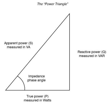
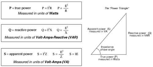
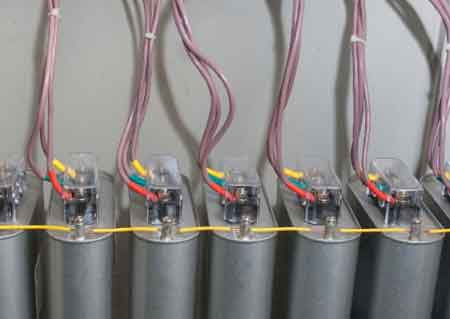
A capacitor bank is a grouping of several capacitors that are connected in series or parallel to store electrical energy and provide reactive power compensation in electrical power systems. Its primary function is to improve power factor and reduce the effects of inductive loading caused by motors, transformers, and other equipment. Additionally, it helps filter out low-order harmonics generated by variable-frequency drives, arc furnaces, and other nonlinear loads, thereby improving overall power quality. By correcting the power factor lag or phase shift and reducing harmonic interference, they ensure the efficient and reliable operation of power systems. Understanding the impact of capacitor banks on apparent power helps engineers ensure proper energy usage and avoid penalties for poor power factor. You can estimate the necessary compensation by using an online apparent power calculator to evaluate your system’s kVA load.
Capacitor banks improve power factor by supplying reactive power to the system. In an electrical power system, inductive loads—such as motors and transformers—cause a phase lag or phase shift between voltage and current, leading to inefficient power use. The stored energy in capacitor units helps to counteract this lag by supplying reactive power, thereby reducing the need for additional reactive power from the grid. At the same time, by suppressing harmonic components in the current waveform, they reduce distortion and help maintain sinusoidal voltage and current waveforms. As a result, the overall power factor improves, losses are reduced, and power quality is preserved across the system. Automatic capacitor switching is controlled by systems, such as an automatic power factor controller, which adjusts reactive power in real-time based on load conditions.
Choosing the appropriate capacitor bank depends on several factors, including the system's voltage, the level of reactive power compensation required, the degree of inductive loading, and the system's harmonic profile. Proper sizing is crucial to avoid overcompensation, which can lead to leading power factor or resonance with harmonic frequencies. Electrical engineering calculations consider the system's power factor lag, inductive loading, harmonic spectrum, and the required improvement in power factor and power quality. It is also essential to consider the bank's configuration, specifically whether it should be connected in series or parallel, and whether it includes detuned reactors to prevent harmonic amplification.
Regular maintenance of capacitor banks is essential to ensure their long-term efficiency, safety, and performance. Common practices include periodic inspections to check for physical damage, loose connections, overheating, or blown capacitor units. Monitoring the voltage rating, harmonic distortion levels, and the condition of the capacitor units is crucial for ensuring consistent reactive power compensation and harmonic filtering. Cleaning, thermal scanning, and dielectric testing of components can prevent malfunctions and prolong the life of the capacitor bank, ensuring it continues to improve power factor, reduce losses, and enhance power quality in electrical systems.
It plays a vital role in managing reactive power and improving the efficiency of electrical power systems. By addressing power factor lag and providing reactive power compensation, they enhance the stability of transmission lines and other power supplies. Selecting, installing, and maintaining banks properly is crucial for optimal performance in both industrial and utility applications. To fully optimize system performance, it's important to combine capacitor bank strategies with accurate power factor calculation and regular monitoring of power factor levels.
Advantages To Instructor-Led Training – Instructor-Led Course, Customized Training, Multiple Locations, Economical, CEU Credits, Course Discounts.
Request For QuotationWhether you would prefer Live Online or In-Person instruction, our electrical training courses can be tailored to meet your company's specific requirements and delivered to your employees in one location or at various locations.