Electricity and Magnetism - Power Explained


Electricity and Magnetism

Electricity and magnetism are interconnected forces forming electromagnetism, which explains electric currents, magnetic fields, and their interactions. These principles power motors, generators, transformers, and more in modern electrical and magnetic systems.


What is: "Electricity and Magnetism"

Electricity and magnetism are fundamental forces in physics that form the basis of electromagnetism.

✅ Describe how electric charges and magnetic fields interact in nature and technology

✅ Underlie the function of motors, transformers, and generators

✅ Explain current flow, induction, and electromagnetic waves

Electricity - What is it?

Electricity is a form of energy that is transmitted through copper conductor wire to power the operation of electrical machines and devices, including industrial, commercial, institutional, and residential lighting, electric motors, electrical transformers, communications networks, home appliances, and electronics.

When charged particles flow through the conductor, we call it "current electricity". This is because when the charged particles flow through wires, electricity also flows. We know that current means the flow of anything in a particular direction. For example, the flow of water. Similarly, the flow of electricity in a specific direction is referred to as an electric current. The interplay of charge, field, and force is explored in what is electric load, covering how power is delivered in electromagnetic systems.

When an electric current flows, it produces a magnetic field, a concept closely tied to Faraday's Law of Induction, which underpins much of modern electrical engineering.


Magnetism  - What is it?

Magnetism is a type of attractive or repulsive force that acts up to certain distance at the speed of light. The distance up to which this attractive or repulsive force acts is called a "magnetic field". Magnetism is caused by the moving electric charges (especially electrons). When two magnetic materials are placed close to each other, they experience an attractive or repulsive force. To understand magnetic field strength and units, our magnetic induction basics in induction page discusses flux and Teslas.


What is the relationship between electricity and magnetism?

In the early days, scientists believed that there were two uniquely separate forces. However, James Clerk Maxwell proved that these two separate forces were actually interrelated.

In 1820, Hans Christian Ørsted observed a surprising phenomenon: when he switched on the battery from which the electric current was flowing, the compass needle moved away from the north pole. After this experiment, he concluded that the electric current flowing through the wire produces a magnetic field.

Electricity and magnetism are closely related to each other. The electric current flowing through the wire produces a circular magnetic field outside the wire. The direction (clockwise or counterclockwise) of this magnetic field depends on the direction of the electric current.

Similarly, a changing magnetic field generates an electric current in a wire or conductor. The relationship between them is called electromagnetism.

Electricity and magnetism are interesting aspects of electrical sciences. We are familiar with the phenomenon of static cling in our everyday lives - when two objects, such as a piece of Saran wrap and a wool sweater, are rubbed together, they cling.

One feature of this that we don't encounter too often is static "repulsion" - if each piece of Saran wrap is rubbed on the wool sweater, then the pieces of Saran wrap will repel when brought near each other. These phenomena are interpreted in terms of the objects acquiring an electric charge, which has the following features:

  • There are two types of charge, which by convention are labelled positive and negative.

  • Like charges repel, and unlike charges attract.

  • All objects may have a charge equal to an integral number of a basic unit of charge.

  • Charge is never created or destroyed.

To explore how electric and magnetic forces interact at a distance, see what is static electricityis, which includes examples like static cling and repulsion.


Electric Fields

A convenient concept for describing these electric current and magnetic current forces is that of electric field currents. Imagine that we have a fixed distribution of charges, such as on the plate below, and bring a test charge Q into the vicinity of this distribution.


img134 
 

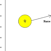
Fig. 1 Test charge in the presence of a fixed charge distribution

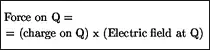
This charge will experience a force due to the presence of the other charges. One defines the electric field of the charge distribution as:


img135

The electric field is a property of this fixed charge distribution; the force on a different charge Q' at the same point would be given by the product of the charge Q' and the same electric field. Note that the electric field at Q is always in the same direction as the electric force.

Because the force on a charge depends on the magnitude of the charges involved and the distances separating them, the electric field varies from point to point, both in magnitude and direction.

By convention, the direction of the electric field at a point is the direction of the force on a positive test charge placed at that point. An example of the electric field due to a positive point charge is given below. 


img136

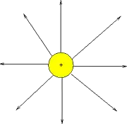
Fig. 2: Electric field lines of a positive charge


Power and Magnetic Fields

A phenomenon apparently unrelated to power is electromagnetic fields. We are familiar with these forces through the interaction of compasses with the Earth's magnetic field, or the use of fridge magnets or magnets on children's toys. Magnetic forces are explained in terms very similar to those used for electric forces:

  • There are two types of magnetic poles, conventionally called North and South
  • Like poles repel, and opposite poles attract

However, this attraction differs from electric power in one important aspect:

  • Unlike electric charges, magnetic poles always occur in North-South pairs; there are no magnetic monopoles.

Later on we will see at the atomic level why this is so.

As in the case of electric charges, it is convenient to introduce the concept of a magnetic field in describing the action of magnetic forces. Magnetic field lines for a bar magnet are pictured below.

img137
 

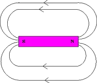
Fig. 3: Magnetic field lines of a bar magnet

One can interpret these lines as indicating the direction that a compass needle will point if placed at that position.

The strength of magnetic fields is measured in units of Teslas (T). One tesla is actually a relatively strong field - the earth's magnetic field is of the order of 0.0001 T.


Magnetic Forces On Moving Charges

One basic feature is that, in the vicinity of a magnetic field, a moving charge will experience a force. Interestingly, the force on the charged particle is always perpendicular to the direction it is moving. Thus, magnetic forces cause charged particles to change their direction of motion, but they do not change the speed of the particle.

This property is utilized in high-energy particle accelerators to focus beams of particles, which ultimately collide with targets to produce new particles, including gamma rays and radio waves.

Another way to understand these forces of electricity and magnetism is to realize that if the force is perpendicular to the motion, then no work is done. Hence, these forces do no work on charged particles and cannot increase their kinetic energy.

If a charged particle moves through a constant magnetic field, its speed stays the same, but its direction is constantly changing. A device that utilizes this property is the mass spectrometer, which is used to identify elements. A basic mass spectrometer is pictured below.


img145
 

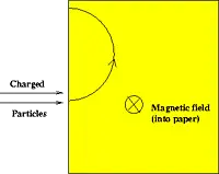
Figure 4: Mass spectrometer

In this device, a beam of charged particles (ions) enters a region of a magnetic field, where they experience a force and are bent in a circular path. The amount of bending depends on the mass (and charge) of the particle, and by measuring this amount one can infer the type of particle that is present by comparing it to the bending of known elements.


Magnet Power From Electric Power

A connection was discovered (accidentally) by Orsted over 100 years ago, when he noticed that a compass needle is deflected when brought into the vicinity of a current-carrying wire. Thus, currents induce magnetic fields in their vicinity. An electromagnet is simply a coil of wires which, when a current is passed through, generates a magnetic field, as below.


img149
 

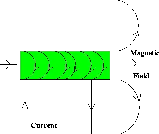
Figure 5: Electromagnet

Another example is in an atom, where an electron is a charge that moves around the nucleus. In effect, it forms a current loop, and hence, a magnetic field may be associated with an individual atom. It is this basic property which is believed to be the origin of the magnetic properties of various types of materials found in nature.

Maxwell's equations (also known as Maxwell's theory) are a set of coupled partial differential equations that, together with the Lorentz force law, form the foundation of classical electromagnetism, which deals with electromagnetic radiation, electromagnetic waves, and electromagnetic force.  For a deeper understanding of the magnetic effects of electrical current, our article on electromagnetic induction explains how magnetic fields can generate electricity in conductors.

Related News

3 PHASE ELECTRICITY

3 Phase Electricity supplies AC three-phase power via 120° phase-shifted sinusoidal waveforms, enabling balanced loads, higher power factor, efficient distribution, and smooth torque for industrial motors across commercial facilities and the electrical grid.


Applications of 3 Phase Electricity in Modern Power Systems

3 phase electricity is referred to alternating current. It is best described as the timing of the electron movements. It is the most common delivery method worldwide because it is a cheaper and easier way to transmit power from one place to another. While this method of electrical transmission is popular in industrial, commercial and institutional power systems, most homes only use single-phase power. For a concise overview, see the three-phase electricity guide for context.


What does it mean?

If wires are in "phase", it means that timing of the electron movement, back and forth, is the same. The electrons are "in step" or "in time".

For newcomers, the basic electricity tutorial explains charge, current, and phase in simple terms.

To transmit and distribute alternating current, it is more efficient to use 3 circuits that are out of sequence. This idea was discovered by Nikola Tesla (1856 -1943). Much of its efficiency is because there is always voltage (electrons moving) in at least one wire.

You can review how alternating current behaves in circuits in the how electricity works resource to see why shifting phases improves continuity.

He found that it is an arrangement that fits in very nicely with generator design. The 120° phasing separation allows close to the optimum spacing and size of the copper conductors around the stator bore. The compatible generator is the cheapest form to make. Design notes for 3-phase power highlight how 120° spacing reduces copper and iron losses.

This type of power is designed especially for large electrical loads where the total electrical load is divided among the three separate phasing sequences. As a result, the wire and transformers will be less expensive than if these large loads were carried on a single system.

Generators usually have three separate windings, each producing its own separate single-phase voltage. Since these windings are staggered around the generator circumference, each of the voltages is "out of phase" with one another. That is, each of the three reaches the maximum and minimum points in the AC cycle at different times.

Definitions of "phase angle" and "phase sequence" are covered in the electricity terms glossary for reference.

Power is generated at electric utilities in this way. But, if this power is better than single phase, why not four, five or six phase? Theoretically, these would be even better, but equipment manufacturers would have to build motors to use it, and that just wouldn't be cost effective given the installed base of equipment that must continue to be powered. Utility practices for distribution are summarized in the electricity supply overview which also outlines standard voltage systems.

The word is often abbreviated using the Greek letter "phi" and is written as a zero with a slash mark through it.

The most important class of load is the electric motor. An induction motor has a simple design, inherently high starting torque, and high efficiency. Such motors are applied in industry for pumps, fans, blowers, compressors, conveyor drives, and many other kinds of motor-driven equipment. A motor will be more compact and less costly than a motor of the same voltage class and rating; and AC motors above 10 HP (7.5 kW) are uncommon. Three phase motors will also vibrate less and hence last longer than motor of the same power used under the same conditions.

Large air conditioning, etc. equipment use motors for reasons of efficiency, economy and longevity.

Resistance heating loads such as electric boilers or space heating may be connected to systems. Electric lighting may also be similarly connected. These types of loads do not require the revolving magnetic field characteristic of motors but take advantage of the higher voltage and power level usually associated with distribution. Fluorescent lighting systems also benefit from reduced flicker if adjacent fixtures are powered from different.

Large rectifier systems may have inputs; the resulting DC current is easier to filter (smooth) than the output of a rectifier. Such rectifiers may be used for battery charging, electrolysis processes such as aluminum production, or for operation of DC motors.

An interesting example of a load is the electric arc furnace used in steelmaking and in refining of ores.

In much of Europe stoves are designed to allow for a feed. Usually the individual heating units are connected between phase and neutral to allow for connection to a supply where this is all that is available.

For homeowners, the home electricity section explains single-phase panels, breakers, and typical loads.


Related Articles

View more

Sources of Electricity Explained

Sources of electricity include fossil fuels, nuclear power, and renewable energy like solar, wind, and hydro. These energy sources provide reliable electricity generation, powering homes, industries, and grids while shaping modern energy systems and sustainability goals.


What are the Sources of Electricity?

Sources of electricity are the various energy systems used to generate electrical power, ranging from conventional fuels to renewable technologies.

✅ Include fossil fuels, nuclear power, and renewable energy

✅ Used in electricity generation across all sectors

✅ Impact cost, sustainability, and environmental footprint

In the modern world, electricity plays a crucial role in our daily lives. As a result, it has become an essential commodity, from powering our homes to running industries. But have you ever wondered where it comes from? Electric power can be generated from various sources with unique characteristics, benefits, and drawbacks. In this article, we'll delve into the main sources of electric power generation and discuss their environmental impacts, costs, and efficiency. Renewable sources, such as hydro, solar, and wind, contrast with alternative electricity options that aim to reduce dependence on fossil fuels.

The primary sources of electric power used to produce electric power can be broadly categorized into renewable and non-renewable resources. Renewable energy sources, such as solar, wind, hydroelectric, geothermal, and biomass, are replenished naturally and have a lower environmental impact than non-renewable sources. Non-renewable energy sources include fossil fuels such as coal, natural gas, and oil, as well as nuclear energy. These resources are finite, and their extraction and utilization contribute to environmental issues like air pollution and climate change. Hydroelectric dams, wind turbines, and solar farms all contribute to global electricity generation, reducing reliance on non-renewable sources.

According to the U.S. Energy Information Administration, global electricity production relies on a mix of renewable and non-renewable sources. While traditional thermal power plants, fueled by coal, natural gas, and nuclear energy, remain central to electricity generation, the rapid growth of solar photovoltaics is transforming how we create and consume electricity. Many nations are investing heavily in utility-scale electricity projects, from massive solar farms to offshore wind facilities, to meet rising demand while reducing emissions. These shifts illustrate how diverse technologies collectively shape the future of reliable and sustainable power.


Fossil Fuels: The Traditional Backbone

Fossil fuels remain the dominant source of electricity worldwide. In 2023, they accounted for roughly 61% of global power generation. In the U.S., about 60% of electric power still comes from coal, natural gas, and oil. These fuels are burned to produce heat, which converts water into steam that drives turbines to generate electric power.

While fossil fuels offer reliability and established infrastructure, they release large amounts of greenhouse gases, contributing significantly to air pollution and climate change.


Nuclear Energy: Low Carbon but Controversial

Nuclear energy provides approximately 9% of the world's electric power and nearly 19% in the United States. It works by splitting atoms (nuclear fission) to release energy that turns water into steam, which then drives turbines.

Nuclear power is highly efficient and emits no carbon during operation. However, it poses concerns regarding radioactive waste, high capital costs, and the potential for catastrophic failures.


Renewable Energy: The Fastest-Growing Sector

Renewable energy sources are expanding rapidly due to technological advances and falling costs. In 2023, they accounted for approximately 30% of global electric power, with wind and solar energy experiencing the fastest growth. Among renewables, Geothermal Electricity harnesses Earth’s internal heat to produce reliable baseload power even in regions with limited solar or wind potential.


Solar Power

Solar energy converts sunlight into electric power using photovoltaic cells, also known as photovoltaic panels. It's scalable, from rooftop systems to massive solar farms, and has seen significant cost reductions over the past decade.


Wind Power

Wind turbines capture kinetic energy from the wind to generate electric power. Wind farms are increasingly common in the U.S., Europe, and China. Like solar energy, wind energy is intermittent, but storage technology is continually improving.


Hydroelectric Power

Hydroelectricity uses flowing water to turn turbines. It's the most established renewable source and provides reliable base-load power. However, large dams can disrupt ecosystems and displace communities. Hydroelectricity stands out as a mature and stable form of renewable generation, as detailed on our Hydroelectricity page.


Geothermal and Biomass

Geothermal taps into Earth’s internal heat, while biomass burns organic material. While smaller in scale, both contribute to energy diversity and localized solutions. Geothermal power generation complements solar, wind, and hydroelectric sources by offering a steady, round-the-clock output, as explained in our detailed guide on Geothermal Electricity.


Comparing Sources of Electricity

Source Global Share (2023) U.S. Share (2023) Key Advantages Key Drawbacks
Fossil Fuels ~61% ~60% Reliable, established infrastructure High emissions, non-renewable
Nuclear ~9% ~19% Low carbon, high efficiency Radioactive waste, high cost
Renewables ~30% ~21% Clean, sustainable, fast-growing Intermittent, resource/location dependent


The diverse world of electric power choices offers a range of technologies that can help meet the growing global demand for energy. By understanding the characteristics, environmental impacts, costs, and efficiencies of these sources, we can make informed decisions about transitioning to cleaner, more sustainable energy systems. As renewable energy technologies continue to advance and energy storage solutions mature, the future of electric power generation is likely to be increasingly dominated by clean, sustainable sources that reduce our impact on the planet and provide reliable power for future generations.


Environmental Impact and Efficiency

The environmental effects of each source vary significantly:

  • Coal and oil are the dirtiest, producing the most CO2 and pollutants.

  • Natural gas emits less CO2 but still contributes to climate change.

  • Nuclear has a low operational footprint but long-term waste issues.

  • Solar and wind energy produce no emissions during use, although manufacturing has some environmental impact.


Efficiency also differs:

  • Natural gas plants can achieve thermal efficiencies exceeding 60%.

  • Nuclear reactors are highly efficient, but they are slow to build.

  • Coal is among the least efficient.

  • Renewables vary based on technology and location.


Cost Considerations

Costs are influenced by technology, fuel, geography, and infrastructure:

  • Solar and wind costs have dropped dramatically, making them competitive with fossil fuels.

  • Nuclear has high upfront costs but low operating costs.

  • Fossil fuels fluctuate in response to changes in market supply and demand.


Future Trends in Power Generation

The energy sector is moving toward decarbonization. Key trends include:

  • Growth in solar and wind capacity

  • Advances in energy storage systems

  • Development of smart grids and microgrids

  • Investment in fusion energy research

Many countries are setting net-zero goals, aiming for cleaner and more sustainable electricity systems.

Electric power can be generated from various sources, each with its trade-offs in terms of cost, efficiency, and environmental impact. While fossil fuels still dominate, the momentum is clearly shifting toward renewable energy sources. A diversified energy mix, supported by smart technologies and forward-looking policies, will power the sustainable future. To understand how energy sources are converted into power, refer to our 'Generate Electricity' article, which describes the entire process from fuel or resource to grid delivery.

Understanding the strengths and weaknesses of each source helps shape a more resilient, efficient, and eco-friendly power generation landscape. Whether from fossil fuels, nuclear, or renewables, every source of electricity must connect to the electricity grid to deliver power where it is needed.


Related Articles


View more

Impedance Definition

Impedance Definition Explained

Understanding the concept of impedance (Z) is crucial for anyone working with or studying electrical circuits, particularly those involving alternating current (AC). To grasp the intricacies of impedance, it is essential to explore its definition and the various factors that come into play.

The term "impedance" is defined as the opposition that an electrical circuit presents to the flow of an alternating current (AC) or voltage. It is a complex quantity that includes both resistance and reactance components, making it vital in AC circuit analysis. Electrical impedance is essential in determining how electrical energy flows through a circuit, and it is influenced by various factors such as resistance, reactance, and frequency.

Resistance and reactance are two key elements that make up impedance. While resistance is the opposition to the flow of direct current (DC), reactance opposes the flow of AC. Reactance itself is composed of two parts: capacitive and inductive impedance. Capacitive impedance is due to the presence of capacitors in the circuit, while inductive impedance results from the presence of inductors.

Impedance is crucial in AC circuit analysis because it enables engineers and technicians to calculate how AC voltage and current behave within a circuit. This knowledge is necessary when designing and troubleshooting electrical systems. Furthermore, understanding impedance helps identify the optimal conditions for efficient energy transfer, as demonstrated by impedance matching.


Impedance matching refers to adjusting the Z of a source and load to match, maximizing the power transfer between the two. This is essential in various applications such as radio frequency (RF) communications, audio systems, and power transmission.

Calculating the total impedance (Z_total) in a circuit involves considering both the resistive and reactive components. For a series circuit, the total impedance is calculated using Ohm's law as follows:


Z_total = √ (R_total^2 + (X_L - X_C)^2)


Here, Z_total represents total impedance, R_total is the total resistance, X_L is the inductive reactance, and X_C is the capacitive reactance. In parallel circuits, the total impedance is computed by determining the reciprocal of the sum of the reciprocals of individual impedances.

Capacitive and inductive impedance play significant roles in AC circuits. As the frequency of the AC signal changes, the impedance of capacitors and inductors in the circuit also changes. As a result, capacitive impedance decreases with increasing frequency while inductive impedance increases. This characteristic can be utilized to design filters that selectively allow specific frequency ranges to pass through, shaping the output signal as desired.

Impedance spectroscopy is a technique that examines the Z of a material or device over a range of frequencies. This process provides valuable information on the electrical properties and behaviour of the material, enabling researchers and engineers to gain insight into various phenomena such as conductivity, dielectric properties, and electrochemical reactions. This knowledge can be applied to optimize the design and performance of various materials and devices.

Impedance definition and its various aspects, including electrical impedance, complex impedance, impedance matching, and impedance spectroscopy, are essential to understanding AC circuit analysis and the behaviour of electrical circuits in different applications. By examining the interplay of resistance and reactance and the influence of electric and magnetic fields, engineers can design and optimize circuits to ensure maximum efficiency and functionality.

View more

Thevenin's Theorem

Thevenin’s Theorem simplifies complex linear circuits into a single voltage source and series resistance, making circuit analysis easier for engineers. It helps calculate current, load behavior, and equivalent resistance in practical electrical systems.


What is Thevenin’s Theorem?

Thevenin’s Theorem is a method in circuit analysis that reduces any linear electrical network to an equivalent circuit with a voltage source (Vth) in series with a resistance (Rth).

✅ Simplifies circuit analysis for engineers and students

✅ Calculates load current and voltage with accuracy

✅ Models equivalent resistance for real-world applications

Thevenin’s Theorem allows any linear, two-terminal circuit to be represented by a single voltage source in series with a resistance.

  • Reduces complex circuits to a simple equivalent consisting of a voltage source and a resistor

  • Makes analyzing load response and network behavior straightforward, saving time and effort

  • Widely used for calculating current, voltage, or power across loads in electrical networks

To fully grasp why Thevenin’s Theorem matters, it helps to revisit the principles of basic electricity, where voltage, current, and resistance form the foundation of all circuit analysis.


Understanding Thevenin’s Theorem

Thevenin’s Theorem is a cornerstone of basic electrical engineering and circuit analysis. First introduced by French engineer Léon Charles Thévenin in the late 19th century, the theorem allows engineers and students alike to simplify a complex electrical network to a single voltage source (known as the Thevenin voltage, Vth) in series with a single resistor (known as the Thevenin resistance, Rth). This is particularly useful when analyzing how a circuit will behave when connected to different loads. Concepts such as Ohm’s Law and electrical resistance work in conjunction with Thevenin’s method, ensuring accurate load and network calculations.

Thevenin’s Theorem states that any linear electrical network can be simplified to an equivalent circuit consisting of a single voltage source in series with a resistance. By removing the load resistance, engineers can calculate the equivalent circuit voltage at the terminals, which represents how the circuit will behave when reconnected. This approach replaces multiple components and ideal voltage sources with one simplified model, making circuit analysis more efficient while preserving accuracy in predicting load behavior.


How Thevenin’s Theorem Works

According to Thevenin’s Theorem, no matter how complicated a linear circuit may be, with multiple sources and resistors, it can be replaced by an equivalent Thevenin circuit. This greatly simplifies the process when you’re only interested in the voltage, current, or power delivered to a specific part of the circuit. The steps typically followed when using Thevenin’s Theorem are:

  1. Identify the portion of the circuit for which you want to find the Thevenin equivalent (usually across two terminals where a load is or will be connected).

  2. Remove the load resistor and determine the open-circuit voltage across the terminals. This voltage is the Thevenin voltage (Vth).

  3. Calculate the Thevenin resistance (Rth) by deactivating all independent voltage sources (replace them with short circuits) and current sources (replace them with open circuits), then determining the resistance viewed from the terminals.

  4. Redraw the circuit as a single voltage source Vth in series with resistance Rth, with the load resistor reconnected.


Why Use Thevenin’s Theorem?

There are several reasons why Thevenin’s Theorem is so widely used in both academic and practical electrical engineering:

  • Simplification – Instead of solving a complex network repeatedly each time the load changes, engineers can just reconnect different loads to the Thevenin equivalent, saving time and reducing the potential for error.

  • Insight – By reducing a circuit to its essential characteristics, it’s easier to understand how changes will affect load voltage, current, or power.

  • Foundation for Further Analysis – Thevenin’s Theorem forms the basis for other network analysis techniques, such as Norton's Theorem, and is fundamental to understanding more advanced topics like maximum power transfer.


Example Application

Imagine a scenario where you need to analyze a circuit with multiple resistors and voltage sources connected in series, with a load resistor at the end. Without Thevenin’s Theorem, calculating the voltage across or current through the load each time you change its resistance would require solving complicated sets of equations. Thevenin’s Theorem allows you to do all the hard work once, finding Vth and Rth, and then quickly see how the load responds to different values.

Illustrative Case: A power supply circuit needs to be tested for its response to varying loads. Instead of recalculating the entire network for each load, the Thevenin equivalent makes these calculations swift and efficient. A deeper look at capacitance and inductance shows how energy storage elements influence circuit behavior when simplified through equivalent models.


Limitations and Conditions

While powerful, Thevenin’s Theorem has limitations:

  • It only applies to linear circuits, those with resistors, sources, and linear dependent sources.

  • It cannot directly simplify circuits containing nonlinear elements such as diodes or transistors in their nonlinear regions.

  • The theorem is most useful for “two-terminal” or “port” analysis; it doesn’t help as much with multiple output terminals simultaneously, though extensions exist.


Connections to Broader Electrical Concepts

Thevenin’s Theorem is closely related to other concepts, such as Norton’s Theorem, which prescribes an equivalent current source and parallel resistance. Both theorems are widely applied in real-world scenarios, including power distribution, signal analysis, and the design of electronic circuits. For example, it's relevant when considering how hydro rates impact load distribution in utility networks.

Thevenin’s Theorem is more than just a trick for simplifying homework—it is a core analytical tool that forms the backbone of practical circuit analysis. Whether you are a student learning circuit theory or an engineer designing power systems, understanding and applying Thevenin’s Theorem is essential.  Understanding current flow and the role of a conductor of electricity provides practical insight into why reducing networks to simple equivalents makes engineering analysis more efficient.


Related Articles


View more

Electricity Meter

An electricity meter measures electrical energy consumption in homes, businesses, and industries. Also called a power meter or energy meter, it records kilowatt-hours, supports billing, monitors usage patterns, and ensures accurate tracking of electrical load.


What is an Electricity Meter?

An electricity meter is a vital device that utility companies use to measure the amount of electric power consumed by a household or business.

✅ Tracks consumption in kilowatt-hours (kWh) for accurate billing

✅ Monitors load, efficiency, and usage trends over time

✅ Essential for power distribution, energy management, and safety


It provides valuable data that helps both consumers and utility companies monitor power consumption, leading to improved energy management and more accurate billing.


How does an electricity meter work?

It measures the amount of power a household or business consumes, typically in kilowatt-hours (kWh). It records usage over time, allowing utility companies to bill customers accordingly.

Various types exist to suit different applications. The most common include:

  • Electromechanical meters (kWh) with a rotating aluminum disc that measures energy flow.

  • Digital meters that display consumption on an electronic screen.

  • Smart meters are advanced digital devices that automatically transmit usage data to the utility.

Smart meters are central to the smart grid, a modernized system designed to improve the efficiency and reliability of power distribution. With a smart device, consumers can access real-time information about their usage while utilities can implement time-of-use billing to encourage energy conservation during peak hours.


Net Metering & Solar Export Meters

For households with solar panels or other distributed energy sources, net recorders facilitate two-way power flow. They measure both the electrical energy consumed from the grid and the power exported back to it. This enables net metering programs, allowing consumers to earn credits or payments for surplus energy, making the adoption of renewable energy more cost-effective.


Communication & Technology Behind Smart Meters

Smart meters are part of the Advanced Metering Infrastructure (AMI), which utilizes communication networks, including RF mesh, cellular, and power line communication (PLC), to securely transmit usage data to the utility. This connectivity enables demand response programs, remote disconnections, and predictive maintenance, while providing consumers with detailed insights via apps and dashboards.


How do I read my Electricity Meter?

Reading your device may seem complicated, but it’s straightforward:

  • Electromechanical types use dials. Read each from left to right, taking the lower number if the pointer is between two digits.

  • Digital types display readings directly on an LCD screen, often cycling through consumption, demand, and tariff data.
    Some utilities also offer web portals or mobile apps that allow consumers to track their daily or hourly usage.


How can I check if my Electricity Meter is accurate?

To test accuracy, turn off all appliances and observe whether the recorder continues to record consumption. If it does, contact your utility for a professional inspection. Most utilities are required by regulation to maintain meter accuracy within specific tolerances defined by ANSI or IEC standards.

One innovation is the prepaid electricity meter, where consumers pay in advance for power. Once the credit is exhausted, the supply is disconnected until it is recharged. This approach enables households to budget more effectively and promotes conscious energy use.


Security & Privacy in Modern Meters

Electricity meter tampering is a significant concern for utilities. Attempts to reduce recorded consumption can lead to safety hazards and financial losses. Modern recorders include anti-tamper seals, encrypted communication, and intrusion detection to protect data integrity and ensure accurate billing. Utilities also conduct regular inspections to detect and prevent fraud.


What is a Smart Electricity Meter, and how does it differ?

It is a digital device that provides real-time usage data, supports two-way communication, and integrates with the smart grid. Unlike traditional recorders, it enables:

  • Automated reading

  • Dynamic tariffs and demand response

  • Access to consumer dashboards, apps, and alerts

These capabilities enhance billing accuracy, empower consumers to lower their energy costs, and facilitate a more flexible and sustainable grid.


Market Adoption & Trends

Smart meter adoption is growing worldwide. According to industry reports, over 1 billion smart meters have been deployed globally, with continued growth expected in North America, Europe, and Asia. In Canada, utilities like BC Hydro have rolled out smart meters to millions of customers, aiming for more reliable service and reduced outages.


Pros, Cons, and Challenges

Electricity meters offer several clear benefits, including accurate billing, improved energy management, integration with renewable energy sources, and reduced costs associated with manual meter reading. However, challenges include upfront costs, connectivity issues, consumer privacy concerns, and potential inaccuracies if meters drift out of calibration. Addressing these ensures the technology continues to deliver long-term benefits.


The Role of Electricity Meters in Energy Management

Understanding how they work, how to read them, and the different types available helps consumers make informed decisions about their energy usage. By verifying accuracy, adopting advanced technologies such as smart and prepaid meters, and utilizing apps and dashboards, households and businesses can gain greater control over their energy costs.

Ultimately, electricity meters are not just billing devices—they are gateways to improved efficiency, consumer empowerment, and a sustainable energy future.


Frequently Asked Questions


Can I read my smart meter remotely?

Yes. Most enable consumers to view their data via apps or online dashboards provided by their utilities.


How accurate are they?

They must comply with standards like ANSI C12 or IEC 62053, ensuring accuracy within strict tolerances.


What happens if it fails?

If it malfunctions, utilities are legally required to replace it and may use historical usage patterns for interim billing.


Related Articles


View more

Three Phase Electricity Explained

Three phase electricity delivers power using three alternating currents that are offset in phase. It provides consistent and efficient energy for industrial, commercial, and high-load applications, improving stability and reducing conductor size.


What is Three Phase Electricity?

Three phase electricity is a power system that uses three alternating currents, each offset by 120 degrees, to deliver constant power flow.

✅ Delivers more efficient and stable power than single-phase systems

✅ Ideal for large motors, commercial buildings, and industrial equipment

✅ Reduces conductor material and energy loss over long distances


Three phase voltage, frequency and number of wires

Three phase electricity is the dominant method of electrical power generation, transmission, and distribution across the industrialized world. Unlike single-phase systems, which rely on a single alternating current, three-phase systems use three separate currents, each 120 degrees out of phase with the others. This setup provides a consistent and balanced power flow, making it significantly more efficient for high-demand applications, such as motors, transformers, and large-scale infrastructure. Understanding the difference between alternating current and direct current is essential to grasp how three-phase systems deliver constant power using offset waveforms.


Understanding the Concept

At the heart of a three-phase system are three sinusoidal waveforms, evenly spaced to maintain a continuous flow of energy. When one phase reaches its peak, the others are in different parts of their cycle, ensuring that at any given moment, some power is being delivered. This creates what is known as constant power transfer, a major advantage over single-phase systems that experience power dips between cycles. Since three-phase systems rely heavily on accurate current flow measurement, it’s important to know what ammeters measure and how they help monitor system balance.

For industrial and commercial operations, this stability translates to increased energy efficiency, extended equipment lifespan, and reduced operating costs. Large electric motors, for example, run more smoothly on three-phase power, which avoids the surging and vibration commonly associated with single-phase inputs.


A Brief History

Three phase electricity wasn’t invented by a single person but emerged through the contributions of several pioneers in the late 19th century. Galileo Ferraris in Italy, Nikola Tesla in the United States, and Mikhail Dolivo-Dobrovolsky in Europe all played crucial roles in developing and refining the idea of three-phase alternating current. Tesla’s patents and Dolivo-Dobrovolsky’s practical systems laid the groundwork for what is now a global standard. Engineers use wattmeters to accurately measure real power in three-phase systems, while Watts Law helps calculate the relationships between voltage, current, and power.


Wye and Delta Configurations

Three-phase systems are typically wired in one of two configurations: the Wye (Y) or Delta (Δ) configuration. Each has specific advantages depending on the application:

  • In a Wye connection, each phase is tied to a central neutral point, allowing for multiple voltage levels within the same system. This is common in both commercial and residential applications, where both high and low voltages are required.

  • A Delta connection utilizes a closed loop with no neutral, a configuration commonly found in industrial setups. It delivers the same voltage between all phases and is ideal for running large motors without needing a neutral return path.

One of the most important relationships in these configurations is the √3 ratio between line voltage and phase voltage, a fundamental aspect that engineers use in calculating load, cable sizing, and protective device coordination.


Technical Benefits

Three-phase systems have built-in advantages that go beyond stability. Because the sum of the three phase currents is zero in a balanced load, a neutral wire is often unnecessary. This reduces the amount of conductor material needed, lowering costs and simplifying design. Additionally, three-phase motors naturally create a rotating magnetic field, eliminating the need for external circuitry to start or maintain rotation.

Another major benefit is that power output remains consistent. In single-phase systems, power drops to zero twice per cycle, but three-phase systems deliver non-pulsating power, which is especially important in sensitive or precision equipment. The function of a busbar is especially important in three-phase distribution panels, helping to manage multiple circuit connections efficiently.


Where and Why It’s Used

While most homes use single-phase electricity, three-phase is the standard in virtually all commercial and industrial environments. Factories, data centers, hospitals, and office buildings rely on it to power everything from HVAC systems and elevators to conveyor belts and industrial machines.

Three-phase is also common in electric vehicle (EV) charging stations and renewable energy systems, where efficient, high-capacity delivery is essential. If you're working with three-phase motors or transformers, knowing the role of a conductor and how electrical resistance affects current flow is fundamental to efficient design.

For sites that only have access to single-phase power, phase converters—whether rotary or digital—can simulate three-phase conditions, enabling them to operate three-phase equipment. This flexibility has made three-phase solutions accessible even in remote or rural areas. Three-phase systems often operate at medium voltage, especially in commercial settings, and their stability can reduce the risks of ground faults.


Voltage Levels and Color Codes

Depending on the region, the standard line and phase voltages vary. In North America, typical voltage values include 120/208 volts and 277/480 volts, whereas in Europe and much of Asia, 230/400 volts is more common. Wiring color codes also differ: red/yellow/blue in Europe, black/red/blue in North America, and other variations depending on the country's electrical code. These standards ensure safety, compatibility, and ease of troubleshooting.


The Global Standard for Power

Three-phase electricity is not just a technical solution; it is the foundation of modern electrical infrastructure. Its ability to deliver large amounts of power efficiently, safely, and reliably has made it the system of choice for more than a century. From powering the machines that build our world to the systems that keep us connected, three-phase electricity remains indispensable.


Related Articles


View more

Sign Up for Electricity Forum’s Newsletter

Stay informed with our FREE Newsletter — get the latest news, breakthrough technologies, and expert insights, delivered straight to your inbox.

Electricity Today T&D Magazine Subscribe for FREE

Stay informed with the latest T&D policies and technologies.
  • Timely insights from industry experts
  • Practical solutions T&D engineers
  • Free access to every issue

Live Online & In-person Group Training

Advantages To Instructor-Led Training – Instructor-Led Course, Customized Training, Multiple Locations, Economical, CEU Credits, Course Discounts.

Request For Quotation

Whether you would prefer Live Online or In-Person instruction, our electrical training courses can be tailored to meet your company's specific requirements and delivered to your employees in one location or at various locations.