What is Open Circuit Voltage? Explained
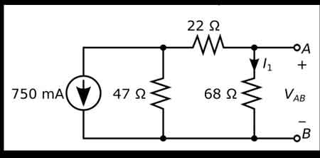

what is open circuit voltage

Open circuit voltage is the potential difference measured across the terminals of a device when no external load is applied. Common in batteries, solar cells, and electrical circuits, it helps evaluate performance, efficiency, and voltage characteristics.


What is Open Circuit Voltage?

It is the maximum voltage measured across terminals when no current flows in the circuit, providing a baseline for performance evaluation.

✅ Indicates battery and solar cell efficiency

✅ Helps assess electrical circuit performance

✅ Defines voltage without current flow

What is open circuit voltage? Often abbreviated as OCV, is an essential concept within electrical engineering, particularly relevant to professionals handling electrical systems or devices. Defined as the electrical potential difference between two points in a circuit when no current flows, OCV represents the maximum voltage achievable without applying a load. For electrical workers, understanding OCV is crucial, as it enables the evaluation of power sources and the identification of potential issues within a circuit before engaging with it under load. Knowledge of OCV benefits electrical workers by providing insights into system readiness, ensuring operational safety, and facilitating troubleshooting for optimal equipment performance. Understanding basic electricity is the foundation for grasping what open circuit voltage means, since it defines how voltage behaves when no current flows.


Determining Open Circuit Voltage

OCV can be measured using instruments like digital multimeters, which provide readings of the maximum electrical potential in the circuit. When conducting a test, it’s essential to measure the resistance between two terminals with no current flow. For instance, if a circuit is connected to a 12-volt battery with no load, the multimeter will display the OCV, which typically matches the battery’s maximum voltage. Similarly, in a solar cell, the OCV provides an indication of the maximum power it can generate when fully charged. Such measurements are helpful in evaluating the state of charge and operational status, providing valuable data to maintain system health. A solid grasp of electrical resistance is also critical, as resistance affects how potential differences are measured when a circuit is open.


Open Circuit Voltage Test

The open-circuit voltage test, also known as the no-load test, is a standard procedure in electrical engineering for assessing a power source's condition when it is not under load. In this test, an engineer connects a voltmeter to the terminals of a circuit to measure the OCV. This process is valuable for detecting issues such as short circuits, high resistance, or compromised wiring, which can lead to performance problems. The results from this test enable electrical professionals to detect weak points in a circuit before it operates under load, ensuring smoother and safer functionality. Open-circuit voltage is directly related to capacitance, as capacitors store electrical potential that can be measured under no-load conditions.


Applications of Open Circuit Voltage 

In practical applications, open circuit voltage is not just a measurement but a vital diagnostic tool. For example, in renewable energy systems, engineers often assess solar cell efficiency by examining its OCV. A solar cell’s OCV indicates its potential output, enabling accurate calculations of energy capacity and state of charge. Understanding OCV also aids in selecting voltage levels appropriate for different components, especially in high-voltage systems where matching component capacity is essential. In this way, OCV serves as a baseline for electrical potential, enabling engineers to optimize systems for both performance and safety. Engineers often compare OCV with direct current behavior, where stable voltages are easier to measure without the influence of alternating loads.

The concept of OCV has safety implications. By knowing the maximum potential voltage in a circuit before activating it, engineers can implement safeguards to avoid overloads or shorts that might occur under load. In electrical troubleshooting, measuring OCV allows for the identification of circuits that aren’t performing optimally, pinpointing faults or abnormal resistance that could lead to hazards. Hence, for electrical workers, mastering OCV measurement is not only about system performance but also about adhering to safety standards that protect both personnel and equipment.


Frequently Asked Questions


What is Open Circuit Voltage?

Open circuit voltage refers to the electrical potential, or maximum voltage, present between two conductors in a circuit when there is no active current flowing. This concept is applicable to both direct current (DC) and alternating current (AC) circuits. In DC systems, the OCV remains stable at a maximum level when no load is connected. In AC circuits, OCV may vary depending on factors such as load fluctuations and circuit design. The measurement of OCV is crucial for determining the performance of various devices, including solar cells, where the state of charge can be observed by checking the OCV. Electrical engineers and technicians can use this information to diagnose issues and assess the readiness of systems for operation. In 3-phase electricity systems, knowing the open circuit voltage helps engineers ensure balance and reliability before load conditions are applied.


Why Open Circuit Voltage Matters

For anyone working in electrical engineering, understanding open-circuit voltage is essential for designing and troubleshooting systems. OCV indicates the maximum voltage a circuit can sustain, helping engineers select compatible components and design for peak efficiency. For instance, when assessing a solar cell, the OCV helps identify the electrical potential it can generate without applying any load. In this way, OCV is a guide to the expected performance under load-free conditions, ensuring that devices will perform within specified limits when placed in actual operation. The concept also closely relates to active power, as OCV provides a baseline for calculating the amount of real power a system can deliver once current begins to flow.


Does open circuit voltage change with temperature?

Yes, temperature can affect open circuit voltage. For example, solar cells typically show a decrease in OCV as temperature rises, which impacts efficiency and energy output.


Is the open circuit voltage always equal to the source voltage?

Not always. While OCV often matches the nominal source voltage, internal resistance, aging, or chemical changes in a battery can cause the measured value to differ slightly.


Can open circuit voltage predict battery health?

OCV can give an indication of a battery’s state of charge, but it is not a complete measure of health. Additional tests, such as load testing, are needed to assess the overall condition.


How does open circuit voltage relate to safety testing?

Measuring OCV before energizing equipment enables engineers to confirm expected voltage levels and prevent hazardous conditions that may arise under load.


Is open circuit voltage used in AC systems as well as DC?

Yes, OCV applies to both AC and DC systems. In AC circuits, variations may occur depending on the design and frequency, whereas DC systems typically provide a stable maximum value.


What is open circuit voltage? Open circuit voltage is more than just a technical measurement; it is a vital reference point for understanding the behavior of batteries, solar cells, and electrical circuits under no-load conditions. By measuring OCV, electrical professionals gain valuable insights into efficiency, reliability, and safety before current flows, ensuring systems are prepared for real-world operation. Whether applied in renewable energy, troubleshooting, or equipment testing, open circuit voltage provides the foundation for sound engineering decisions and safer electrical practices.


Related Articles


Related News

Electricity and Electrical Energy

Electricity powers modern engineering, driving circuits, voltage, current, and AC/DC power systems for transmission, distribution, and control. Engineers analyze resistance, impedance, and frequency, optimize grids, and integrate renewables with transformers, generators, and smart controls.


What Is Electricity?

Electricity is the flow of charge enabling energy conversion, signal transmission, and power control across circuits.

✅ Quantified by voltage (V), current (A), and power (W)

✅ Governed by Ohm's Law, Kirchhoff's Laws, and Maxwell's equations

✅ Transmitted via grids using AC, transformers, and protection


Electricity is a manufactured product. It is not something you pump out of the ground or mine or collect from the sun or wind. For a clear primer on definitions and units, visit what electricity is to ground these ideas.

Electric power is manufactured from a rotating machine that we call an electrical generator. After it is generated, (manufactured) it is then delivered through copper wires to where it is utilized If you want to see how turbines and alternators convert motion into power, explore the electricity generator to understand key components and operation.

Electricity - most people don't understand what it is. They just turn on the light switch or start the appliance or push the button and something works. It's only when there is no electric power available that we start to consider the importance of it in our daily personal and working lives. A step-by-step explanation of fields, voltage, and current is outlined at how electricity works for readers new to the topic.

But the invention of the machine to generate power is right next to the invention of the printing press in the list of major contributions to the advancement of human civilization. For context on pioneers from Faraday to Tesla, review who invented electricity to connect invention with modern grids.

Without it, we would be burning wood and coal to heat our homes and businesses and using oil and candles to light our way in the dark. That is the way it was for humans civilization for countless centuries. Only since the invention of the electric generator have humans been able to advance in every aspect of modern life. In fact, modern living is defined by electric power. This shift from fuels to electrons is traced in the history of electricity to show how infrastructure reshaped society.

We have assembled a series of pages in our web site to help you to understand the business of electricity - how it works and how it is used. To dive deeper into fundamentals before the business aspects, start with electricity: how it works for a concise technical overview.

We hope that you can use this information to better understand the technology and issues behind the manufacturing of electric power. Further reading on thermal, hydro, and renewable pathways is available at how electricity is generated to see how manufacturing methods compare.


Related Articles

View more

Tidal Electricity From Wave Action

Tidal electricity converts predictable ocean tides into renewable energy using tidal turbines, barrages, and lagoons, delivering stable baseload marine power, efficient grid integration, low carbon emissions, and robust reliability through advanced hydrodynamics and power electronics.


What Is Tidal Electricity?

Tidal electricity generates grid power from ocean tides via turbines or barrages, providing predictable, low-carbon output.

✅ Uses tidal stream turbines, barrages, and lagoons

✅ Predictable output enhances grid stability and capacity planning

✅ Power electronics enable efficient conversion and grid integration


Tidal electricity is obtained by utilizing the recurring rise and fall of coastal waters. Marginal marine basins are enclosed with dams, making it possible to create differences in the water level between the ocean and the basins. The oscillatory flow of water filling or emptying the basins is used to drive hydraulic turbines which propel wave generators. As a specialized branch of hydroelectricity, tidal schemes convert predictable water level differences into dispatchable power.

The cyclical movement of seawater exemplifies how water electricity systems depend on fluid dynamics and site geometry.

Large amounts of wave generation could be developed in the world's coastal regions having tides of sufficient range, although even if fully developed this would amount to only a small percentage of the world's potential hydroelectric power. In global electricity production portfolios, tidal energy typically plays a niche role alongside other renewables.

Because installations are coastal and infrastructure-intensive, they can contribute to regional green electricity targets with long service lives.

It is produced by turbines operated by tidal flow. Many ideas for harnessing the tides were put forward in the first half of the 20th century, but no scheme proved technically and economically feasible until the development by French engineers of the plan for the Rance power plant in the Gulf of Saint-Malo, Brittany, built 1961–67. A dam equipped with reversible turbines (a series of fixed and moving blades, the latter of which are rotated) permits the tidal flow to work in both directions, from the sea to the tidal basin on the flood and on the ebb from the basin to the sea. The Rance plant has 24 power units of 10,000 kilowatts each; about seven-eighths of the power is produced on the more controllable ebb flow. The sluices fill the basin while the tide is coming in and are closed at high tide. Emptying does not begin until the ebb tide has left enough depth of fall to operate the turbines. Conversely, the turbines are worked by the incoming tide to the basin. With reversible bulb turbines, both ebb and flood flows generate electricity with high capacity factors during spring tides.

Compared with windmills for electricity, tidal turbines benefit from dense water flow that yields steadier torque.

The Soviet Union completed construction in 1969 of a plant of about 1,000 kilowatts on the White Sea. Other sites of interest for tidal power plants include the Bay of Fundy in Canada, where the tidal range reaches more than 15 m (49 feet). Although large amounts of power are available from the tides in favourable locations, this power is intermittent and varies with the seasons. Grid planners often pair tidal plants with storage and flexible resources used in electricity windmill operations to smooth variability.


Related Articles

View more

What is Open Circuit Voltage? Explained

Open circuit voltage is the potential difference measured across the terminals of a device when no external load is applied. Common in batteries, solar cells, and electrical circuits, it helps evaluate performance, efficiency, and voltage characteristics.


What is Open Circuit Voltage?

It is the maximum voltage measured across terminals when no current flows in the circuit, providing a baseline for performance evaluation.

✅ Indicates battery and solar cell efficiency

✅ Helps assess electrical circuit performance

✅ Defines voltage without current flow

What is open circuit voltage? Often abbreviated as OCV, is an essential concept within electrical engineering, particularly relevant to professionals handling electrical systems or devices. Defined as the electrical potential difference between two points in a circuit when no current flows, OCV represents the maximum voltage achievable without applying a load. For electrical workers, understanding OCV is crucial, as it enables the evaluation of power sources and the identification of potential issues within a circuit before engaging with it under load. Knowledge of OCV benefits electrical workers by providing insights into system readiness, ensuring operational safety, and facilitating troubleshooting for optimal equipment performance. Understanding basic electricity is the foundation for grasping what open circuit voltage means, since it defines how voltage behaves when no current flows.


Determining Open Circuit Voltage

OCV can be measured using instruments like digital multimeters, which provide readings of the maximum electrical potential in the circuit. When conducting a test, it’s essential to measure the resistance between two terminals with no current flow. For instance, if a circuit is connected to a 12-volt battery with no load, the multimeter will display the OCV, which typically matches the battery’s maximum voltage. Similarly, in a solar cell, the OCV provides an indication of the maximum power it can generate when fully charged. Such measurements are helpful in evaluating the state of charge and operational status, providing valuable data to maintain system health. A solid grasp of electrical resistance is also critical, as resistance affects how potential differences are measured when a circuit is open.


Open Circuit Voltage Test

The open-circuit voltage test, also known as the no-load test, is a standard procedure in electrical engineering for assessing a power source's condition when it is not under load. In this test, an engineer connects a voltmeter to the terminals of a circuit to measure the OCV. This process is valuable for detecting issues such as short circuits, high resistance, or compromised wiring, which can lead to performance problems. The results from this test enable electrical professionals to detect weak points in a circuit before it operates under load, ensuring smoother and safer functionality. Open-circuit voltage is directly related to capacitance, as capacitors store electrical potential that can be measured under no-load conditions.


Applications of Open Circuit Voltage 

In practical applications, open circuit voltage is not just a measurement but a vital diagnostic tool. For example, in renewable energy systems, engineers often assess solar cell efficiency by examining its OCV. A solar cell’s OCV indicates its potential output, enabling accurate calculations of energy capacity and state of charge. Understanding OCV also aids in selecting voltage levels appropriate for different components, especially in high-voltage systems where matching component capacity is essential. In this way, OCV serves as a baseline for electrical potential, enabling engineers to optimize systems for both performance and safety. Engineers often compare OCV with direct current behavior, where stable voltages are easier to measure without the influence of alternating loads.

The concept of OCV has safety implications. By knowing the maximum potential voltage in a circuit before activating it, engineers can implement safeguards to avoid overloads or shorts that might occur under load. In electrical troubleshooting, measuring OCV allows for the identification of circuits that aren’t performing optimally, pinpointing faults or abnormal resistance that could lead to hazards. Hence, for electrical workers, mastering OCV measurement is not only about system performance but also about adhering to safety standards that protect both personnel and equipment.


Frequently Asked Questions


What is Open Circuit Voltage?

Open circuit voltage refers to the electrical potential, or maximum voltage, present between two conductors in a circuit when there is no active current flowing. This concept is applicable to both direct current (DC) and alternating current (AC) circuits. In DC systems, the OCV remains stable at a maximum level when no load is connected. In AC circuits, OCV may vary depending on factors such as load fluctuations and circuit design. The measurement of OCV is crucial for determining the performance of various devices, including solar cells, where the state of charge can be observed by checking the OCV. Electrical engineers and technicians can use this information to diagnose issues and assess the readiness of systems for operation. In 3-phase electricity systems, knowing the open circuit voltage helps engineers ensure balance and reliability before load conditions are applied.


Why Open Circuit Voltage Matters

For anyone working in electrical engineering, understanding open-circuit voltage is essential for designing and troubleshooting systems. OCV indicates the maximum voltage a circuit can sustain, helping engineers select compatible components and design for peak efficiency. For instance, when assessing a solar cell, the OCV helps identify the electrical potential it can generate without applying any load. In this way, OCV is a guide to the expected performance under load-free conditions, ensuring that devices will perform within specified limits when placed in actual operation. The concept also closely relates to active power, as OCV provides a baseline for calculating the amount of real power a system can deliver once current begins to flow.


Does open circuit voltage change with temperature?

Yes, temperature can affect open circuit voltage. For example, solar cells typically show a decrease in OCV as temperature rises, which impacts efficiency and energy output.


Is the open circuit voltage always equal to the source voltage?

Not always. While OCV often matches the nominal source voltage, internal resistance, aging, or chemical changes in a battery can cause the measured value to differ slightly.


Can open circuit voltage predict battery health?

OCV can give an indication of a battery’s state of charge, but it is not a complete measure of health. Additional tests, such as load testing, are needed to assess the overall condition.


How does open circuit voltage relate to safety testing?

Measuring OCV before energizing equipment enables engineers to confirm expected voltage levels and prevent hazardous conditions that may arise under load.


Is open circuit voltage used in AC systems as well as DC?

Yes, OCV applies to both AC and DC systems. In AC circuits, variations may occur depending on the design and frequency, whereas DC systems typically provide a stable maximum value.


What is open circuit voltage? Open circuit voltage is more than just a technical measurement; it is a vital reference point for understanding the behavior of batteries, solar cells, and electrical circuits under no-load conditions. By measuring OCV, electrical professionals gain valuable insights into efficiency, reliability, and safety before current flows, ensuring systems are prepared for real-world operation. Whether applied in renewable energy, troubleshooting, or equipment testing, open circuit voltage provides the foundation for sound engineering decisions and safer electrical practices.


Related Articles


View more

Power System Analysis Explained

Power System Analysis enables load flow studies, fault calculations, stability assessment, state estimation, and contingency analysis for grids, integrating SCADA data, protection coordination, and reliability planning to optimize transmission, distribution, and generation performance.


What Is Power System Analysis?

Power System Analysis models grid behavior to ensure stability, reliability, efficiency, and secure operation.

✅ Load flow, short-circuit, and transient stability studies

✅ State estimation, SCADA integration, and contingency analysis

✅ Protection coordination, reliability assessment, and optimization


Power system analysis (PSA) is an essential electrical system component. It helps to ensure that the electrical system operates efficiently, reliably, and safely. Power flow analysis, fault study, stability investigation, renewable energy integration, grid modernization, and optimization techniques are all essential concepts in PSA. As our society continues to rely heavily on electricity, PSA will remain a vital tool for ensuring the stability and reliability of the electrical system. For foundational context on how electricity underpins these studies, see this primer on what electricity is and how it behaves.

One of the critical concepts in PSA is power system modelling. Modelling is creating a mathematical model of the electrical system. This model includes all the system components, such as generators, transformers, transmission lines, and distribution networks. Modelling is essential as it provides a detailed understanding of the system's workings. Engineers commonly begin by drafting a single-line diagram to visualize component interconnections and power paths.

Another critical concept in PSA is power flow investigation, also known as load flow investigation. Power flow analysis calculates the electrical system's voltages, currents, and power flows under steady-state conditions. A power flow study helps determine whether the electrical system can deliver electricity to all the loads without overloading any system component. The results of the power flow investigation are used to plan the system's expansion and ensure that it operates efficiently and reliably. In practice, load-flow outputs are interpreted within the broader context of electric power systems to validate voltage profiles and thermal limits.

Fault study is another crucial component of PSA. A fault study is a process of analyzing the system's behaviour during a fault condition. This needs a short circuit analysis. A fault is abnormal when the system has a short or open circuit. A fault study helps to determine the fault's cause and develop strategies to prevent or mitigate the effects of faults in the future.

Stability investigation is also an important aspect of PSA. Stability investigation is the process of analyzing the system's behaviour under dynamic conditions. For example, the system is subject to dynamic disturbances, such as sudden load or generator output changes, which can cause instability. Stability investigation helps ensure the system can withstand these disturbances and operate reliably.

The transient investigation is another key concept in PSA. The transient study analyzes the electrical system's behaviour during transient conditions, such as switching operations or lightning strikes. A brief investigation helps ensure the system can withstand these transient conditions and operate reliably.

Renewable energy integration is an emerging concept in PSA. As more renewable energy sources, such as wind and solar power, are integrated into the energy system, PSA becomes increasingly essential to ensure the stability and reliability of the electrical system. Understanding how generation mixes are formed benefits from a primer on how electricity is generated across thermal, hydro, and renewable technologies.

Grid modernization is also a crucial aspect of PSA. As the system ages, it becomes increasingly important to modernize the grid to ensure that it can meet the demands of modern society. Therefore, PSA is used to develop strategies to modernize the grid and ensure it operates efficiently, reliably, and safely. Many modernization roadmaps align with the evolving architecture of the electricity grid as utilities adopt automation, advanced metering, and distributed resources.

Finally, protection coordination and optimization techniques are essential components of PSA. Protection coordination involves developing strategies to protect the electrical system from faults and other abnormal conditions. Optimization techniques involve developing strategies to optimize the system's operation and ensure it operates efficiently and reliably. Because reactive power and losses affect dispatch, monitoring and improving power factor can materially enhance system efficiency.


What is power system analysis, and why is it important?

PSA analyzes the electrical system to ensure it operates efficiently, reliably, and safely. Therefore, it is crucial to identify potential problems before they occur and develop strategies to prevent or mitigate the effects of these problems. In addition, PSA is important because it helps ensure that the electrical system can meet the demands of modern society, which relies heavily on electricity.


How is power flow analysis performed?

Power flow analysis, or load flow analysis, is performed using a mathematical model. The model includes all the power system components, such as generators, transformers, transmission lines, and distribution networks. A power flow study calculates the electrical system's voltages, currents, and power flows under steady-state conditions. The results of the power flow investigation are used to plan the electrical system's expansion and ensure that it operates efficiently and reliably. These studies also quantify reactive power behavior, making concepts like what power factor is directly applicable to planning and operations.


What is fault analysis, and how is it used?

Fault analysis is analyzing the system's behaviour during a fault condition. A fault is abnormal when the system has a short or open circuit. A fault study is used to determine the fault's cause and develop strategies to prevent or mitigate the effects of faults in the future. Fault analysis is crucial in ensuring the safety and reliability of the electrical system.


What are the different stability study techniques used?

Several stability investigation techniques are used in PSA to measure transient, small-signal, and voltage stability. Transient stability is used to analyze the behaviour of the distribution under dynamic conditions, such as sudden changes in load or generator output. Small-signal stability measurement analyzes the system's behaviour under small disturbances. Finally, voltage stability measurement is used to analyze the system's behaviour under steady-state conditions and determine the system's voltage limits.


How does renewable energy integration affect power system analysis?

Renewable energy integration is an emerging concept in PSA. As more renewable energy sources, such as wind and solar power, are integrated into the electrical system, PSA becomes increasingly essential to ensure the stability and reliability of the system. Renewable energy sources are intermittent, which can cause fluctuations in the system. PSA is used to develop strategies to integrate renewable energy sources into the system while ensuring its stability and reliability.


What are the challenges of grid modernization, and how does power system analysis help overcome them?

Grid modernization is a crucial aspect of PSA. As the system ages, it becomes increasingly important to modernize the grid to ensure that it can meet the demands of modern society. Grid modernization involves upgrading the system to incorporate new technologies, such as smart grid technologies and renewable energy sources. The challenges of grid modernization include the need for new infrastructure, the integration of new technologies, and new regulatory frameworks. PSA is used to develop strategies to overcome these challenges and to ensure that the electrical system operates efficiently, reliably, and safely.


How can optimization techniques improve system efficiency and reliability in power system analysis?

Optimization techniques can be used in PSA to improve system efficiency and reliability. These techniques involve developing strategies to optimize the system's operation and ensure it operates efficiently and reliably. For example, optimization techniques can determine the optimal generation and transmission of power, improve load forecasting, and develop strategies to reduce energy consumption. PSA is crucial in developing and implementing these optimization techniques, which help improve the electrical system's overall efficiency and reliability, leading to a more sustainable and cost-effective electrical power system.


Related Articles

View more

DC Current - Electricity Explained

DC current delivers unidirectional electron flow with constant polarity, powering circuits, batteries, and electronics; characterized by steady voltage, low ripple, and efficient distribution via rectifiers, converters, and regulated power supplies in electrical engineering.


What Is DC Current?

DC current is unidirectional electron flow with constant polarity, providing steady voltage for efficient power delivery

✅ Provides constant voltage for sensitive electronics and logic circuits

✅ Generated by batteries, fuel cells, solar PV; produced via rectification

✅ Enables precise control in motors, sensors, and industrial automation


DC current is essential to electrical energy, powering devices ranging from small electronic gadgets to electric vehicles. We can appreciate its significance in modern life by understanding its properties, applications, and relationship to other electrical concepts such as voltage, resistance, and Ohm's Law. Despite its limitations in power transmission over long distances, the use of DC current in solar energy systems and electric vehicles continues to demonstrate its vital role in an increasingly electrified world. For a practical primer, the direct current overview clarifies key concepts used in everyday systems today.


Direct current (DC) and alternating current (AC) are the two primary forms of current that power various electrical devices and systems. As the name suggests, direct current flows in a single, unidirectional direction, while alternating current oscillates in direction and magnitude. This article will explore the fundamental concepts of DC current, its applications, and its relationship to other aspects of electricity. For deeper contrasts, the difference between AC and DC guide expands on efficiency, safety, and conversion considerations for designers.

It is the flow of electric charge (electrons) in a consistent direction across a conductor, such as a wire. The consistent flow differentiates it from AC, where the direction of the flow periodically reverses. One of the most significant differences between DC and AC current is their power transmission method. DC systems transmit power at a constant voltage, while AC power alternates at a specific frequency. Complementing this, an accessible alternating current explainer details waveform behavior and frequency effects relevant to grid systems.

Electrical circuits using DC current play an essential role in many everyday devices and systems. Some common applications of DC current include batteries, solar panels, and electronic devices. Batteries are a prime example of a DC power source, as they generate a steady flow of electrons from one terminal to another. Solar panels, on the other hand, convert sunlight into DC electrical energy, which can then be stored in batteries or transformed into AC for use in homes or businesses. If you're new to the topic, this current electricity introduction connects sources like batteries and solar arrays to practical loads in simple terms.

In DC current circuits, voltage and resistance are essential factors influencing the flow of electric charge. Voltage refers to the electric potential difference between two points, whereas resistance represents the opposition to the flow of current. Ohm's Law, a fundamental principle in electrical engineering, states that the current flowing through a conductor between two points is directly proportional to the voltage across those points and inversely proportional to the resistance between them. In other words, the higher the voltage or, the lower the resistance, the greater the current. A concise current reference ties these relationships to measurement practices and typical units used in labs.

DC current also plays a critical role in electric vehicles, where it is converted from high-voltage batteries to the required voltage for the electric motor. This conversion from DC to AC is essential because electric motors typically function on AC power.

DC current presents both advantages and disadvantages. One of its main benefits is its simplicity, as it maintains a constant voltage and current flow, making it easier to work with in electronic devices. Additionally, its unidirectional flow allows for more efficient power storage in batteries. However, one significant drawback is that it could be better suited for long-distance power transmission, as it suffers from substantial power loss over long distances.

The story of electricity would be incomplete without mentioning the famous "Battle of the Currents" between Thomas Edison, a staunch advocate of DC systems, and George Westinghouse, who supported AC systems. Ultimately, AC power emerged as the winner for power distribution due to its ability to transmit power over long distances with minimal energy loss. For historical and conceptual grounding, an electricity definition frames how these terms evolved across scientific practice.


DC Current Calculator Explained

A DC current calculator is a tool that helps to determine the direct current flowing through an electrical circuit based on known values of voltage, resistance, and sometimes power. It is used to simplify and verify calculations related to DC circuits and ensure proper circuit design, maintenance, and troubleshooting. The calculator uses Ohm's Law and the power equation as the basis for its calculations.

Ohm's Law states that the current (I) flowing through a conductor between two points is directly proportional to the voltage (V) across those points and inversely proportional to the resistance (R) between them. The formula is:

I = V / R

In addition to Ohm's Law, the power equation can be used to determine the current in a circuit when the power (P) and voltage (V) are known:

P = IV

By rearranging this formula, we can find the current:

I = P / V

To use a calculator, you will typically input the known voltage, resistance, and/or power values, and the calculator will solve for the unknown variable (in this case, the current). For safe circuit operation, some calculators may provide additional information, such as power dissipation or required resistor wattage. If you need a refresher before using calculation tools, this basic electricity primer reviews units, symbols, and safety fundamentals that prevent common mistakes.

A calculator is especially useful for electrical engineers, technicians, and hobbyists working with DC circuits to verify their calculations or diagnose issues within the circuit. It can help ensure the proper functioning of electronic devices, efficient energy usage, and the safety of the electrical components within a system.


Related Articles

View more

Capacitance Explained

Capacitance: Understanding the Ability to Store Electricity

Capacitance is an essential concept in electrical circuits, and it describes the ability of a capacitor to store electrical energy. Capacitors are electronic components used in many circuits to perform various functions, such as filtering, timing, and power conversion. Capacitance is a measure of a capacitor's ability to store electrical energy, and it plays a crucial role in the design and operation of electrical circuits. This article provides an overview of capacitance, including its definition, SI unit, and the difference between capacitor and capacitance.


What is Capacitance?

Capacitance is the ability of a capacitor to store electrical charge. A capacitor consists of two conductive plates separated by a dielectric material. The conductive plates are connected to an electrical circuit, and the dielectric material is placed between them to prevent direct contact. When a voltage source is applied to the plates, electrical charge builds up on the surface of the plates. The amount of charge that a capacitor can store is determined by its capacitance, which depends on the size and distance between the plates, as well as the dielectric constant of the material.

The energy storing capability of a capacitor is based on its capacitance. This means that a capacitor with a higher capacitance can store more energy than a capacitor with a lower capacitance. The energy stored in a capacitor is given by the formula:

Energy (Joules) = 0.5 x Capacitance (Farads) x Voltage^2

The ability to store energy is essential for many applications, including filtering, timing, and power conversion. Capacitors are commonly used in DC circuits to smooth out voltage fluctuations and prevent noise. They are also used in AC circuits to filter out high-frequency signals.


What is Capacitance and the SI Unit of Capacitance?

Capacitance is defined as the ratio of the electrical charge stored on a capacitor to the voltage applied to it. The SI unit of capacitance is the Farad (F), which is defined as the amount of capacitance that stores one coulomb of electrical charge when a voltage of one volt is applied. One Farad is a relatively large unit of capacitance, and most capacitors have values that are much smaller. Therefore, capacitors are often measured in microfarads (µF) or picofarads (pF).

The capacitance of a capacitor depends on several factors, including the distance between the plates, the surface area of the plates, and the dielectric constant of the material between the plates. The dielectric constant is a measure of the ability of the material to store electrical energy, and it affects the capacitance of the capacitor. The higher the dielectric constant of the material, the higher the capacitance of the capacitor.


What is the Difference Between Capacitor and Capacitance?

Capacitor and capacitance are related concepts but are not the same thing. Capacitance is the ability of a capacitor to store electrical energy, while a capacitor is an electronic component that stores electrical charge. A capacitor consists of two conductive plates separated by a dielectric material, and it is designed to store electrical charge. Capacitance is a property of a capacitor, and it determines the amount of electrical charge that the capacitor can store. Capacitance is measured in Farads, while the capacitor is measured in units of capacitance, such as microfarads (µF) or picofarads (pF).


What is an Example of Capacitance?

One example of capacitance is a common electronic component known as an electrolytic capacitor. These capacitors are used in a wide range of electronic circuits to store electrical energy, filter out noise, and regulate voltage. They consist of two conductive plates separated by a dielectric material, which is usually an electrolyte. The electrolyte allows for a high capacitance, which means that these capacitors can store a large amount of electrical energy.

Another example of capacitance is the human body. Although the capacitance of the human body is relatively small, it can still store a significant amount of electrical charge. This is why people can sometimes feel a shock when they touch a grounded object, such as a metal doorknob or a handrail. The capacitance of the human body is affected by several factors, including the size and shape of the body, as well as the material and proximity of the objects it comes into contact with.

View more

Sign Up for Electricity Forum’s Newsletter

Stay informed with our FREE Newsletter — get the latest news, breakthrough technologies, and expert insights, delivered straight to your inbox.

Electricity Today T&D Magazine Subscribe for FREE

Stay informed with the latest T&D policies and technologies.
  • Timely insights from industry experts
  • Practical solutions T&D engineers
  • Free access to every issue

Live Online & In-person Group Training

Advantages To Instructor-Led Training – Instructor-Led Course, Customized Training, Multiple Locations, Economical, CEU Credits, Course Discounts.

Request For Quotation

Whether you would prefer Live Online or In-Person instruction, our electrical training courses can be tailored to meet your company's specific requirements and delivered to your employees in one location or at various locations.