Latest Motors and Drives Articles
VFD Programming: Crucial For Motor Control
VFD programming is not about entering parameters. It is about deciding how a motor will behave under stress, fault conditions, load changes, and long-term operation. A poorly programmed drive may run a motor, but it will not protect it, stabilize it, or deliver predictable performance. In industrial systems, those differences determine energy cost, maintenance cycles, and failure risk.
This is why VFD programming is a reliability discipline, not a commissioning formality. Every parameter influences torque response, thermal loading, mechanical stress, and electrical stability. When configuration is rushed or copied from defaults, motors may appear healthy while accumulating invisible damage that…
View more
Sign Up for Electricity Forum’s Motors and Drives Newsletter
Stay informed with our FREE Motors and Drives Newsletter — get the latest news, breakthrough technologies, and expert insights, delivered straight to your inbox.
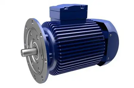
Electric Motor Design Engineering
Electric motor design enhances efficiency, torque, and speed control by applying principles of electromagnetism. Optimized stator, rotor, and winding configurations deliver reliable performance, durability, and energy savings across industrial power applications.
Electric Motor Design: Real-World Examples and Uses
VFD Training
Electric Motor Testing Training
Request a Free Training Quotation
Types of Electric Motors
Electric motors, including both AC motors and DC motors, come in a wide range of shapes and sizes. Some are standardized for general-purpose use, while others are tailored for specific applications. The main categories include:
AC Induction Motors – rugged, low-cost, and common in industrial…
View more
What Does VFD Stand For?
A VFD stands for Variable Frequency Drive, also known as an adjustable frequency drive or AC drive, controls motor speed and torque by varying voltage and frequency, thereby helping systems conserve energy, reduce wear, and enhance process performance across various applications.
What Does VFD Stand For?
VFD Training
Electric Motor Testing Training
Request a Free Training Quotation
For professionals in these fields, understanding VFDs is essential due to their ability to enhance efficiency, optimize energy use, and improve the performance of electric motors. By varying the frequency and voltage of the power supply, VFDs enable precise control over speed…
View more

Variable Frequency Drive HVAC Explained
A Variable Frequency Drive (VFD) in HVAC systems adjusts motor speed and torque to control fans, pumps, and compressors, thereby boosting energy efficiency, lowering costs, reducing wear, and enhancing comfort in heating, ventilation, and air conditioning.
Principles of Variable Frequency Drives in HVAC
VFD Training
Electric Motor Testing Training
Request a Free Training Quotation
Variable Frequency Drives (VFDs) in HVAC systems allow operators to adjust the speed of motors rather than running at full speed continuously. By enabling users to control the speed of fans, pumps, and compressors, variable frequency drives VFDs and variable speed drives deliver significant energy…
View more
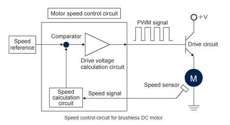
DC Motor Speed Control
DC motor speed control adjusts rotational speed using voltage variation, PWM, or feedback systems. Essential for automation, robotics, and precise motor performance. Ensures efficient torque control and enhances application reliability.
DC Motor Speed Control Explained: What You Need to Know
VFD Training
Electric Motor Testing Training
Request a Free Training Quotation
Understanding how to regulate the speed of these motors precisely is essential for optimizing performance, efficiency, and safety across a wide range of applications. Let's delve into the core concepts, equipping electricians with the knowledge to manage and troubleshoot these systems effectively. From the fundamentals of Pulse Width…
View more
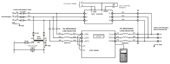
Variable Frequency Drive
Variable frequency drive optimizes AC motor control using an inverter and PWM for variable speed, torque management, soft start, and energy savings in HVAC, pumps, conveyors, compressors, and industrial automation.
Understanding How a Variable Frequency Drive Works
In industrial automation, motor control has always been a critical aspect of system design. However, one device that has revolutionized the way we approach this is the variable frequency drive (VFD). By understanding how adjustable frequency drives work, how they improve energy efficiency, and the right way to choose, install, and configure them, you can harness their full potential to optimize your…
View more
Learn How An Electric Motor Transforms Potential Energy Into Mechanical Energy
An electric motor transforms potential energy into mechanical energy. Via electromagnetic induction, it delivers shaft torque through rotor-stator interaction, optimizing efficiency in AC and DC drives, automation, robotics, and industrial motion control.
The Science Behind an Electric Motor's Transformation of Potential Energy Into Mechanical Energy
An electric motor transforms potential energy into mechanical energy, a process that underpins countless modern technologies and industrial applications. It is similar to how an electric motor transforms electrical energy into mechanical energy. For engineering and maintenance professionals, understanding this transformation is critical to optimizing machinery, ensuring energy efficiency, and maintaining operational reliability. Electric…
View more