How to Test a Contactor Explained
By William Conklin, Technical Editor
By William Conklin, Technical Editor
Our customized live online or in‑person group training can be delivered to your staff at your location.

To test a contactor, check coil voltage, inspect for continuity across contacts, and verify proper operation with a multimeter. Ensure power is off before testing. These steps help identify failure in HVAC or motor circuits.
Visit Our Electrical Troubleshooting Training Course
How to Test a Contactor is a critical procedure in diagnosing and ensuring the reliability of electrical systems, especially in air conditioning and heating applications. When they fail, they can cause system breakdowns, continuous running, or intermittent performance, which can be costly and unsafe. Testing allows electrical workers to verify its operational integrity, pinpoint potential issues, and determine if a replacement or repair is necessary. This article outlines a clear, step-by-step approach to safely and accurately test a contactor using a multimeter, empowering workers to maintain efficient and dependable equipment performance. For a deeper understanding of the tools involved in this process, see our electrical test equipment guide, which covers essential instruments for accurate insulation resistance testing.
It is a device used to manage electrical flow within a system. In air conditioning units, it regulates the connection between various components, like compressors and fans, to control cooling and heating. When the unit is powered on, it responds to a low-voltage signal, activating a magnetic field that enables higher-voltage connections. There are two primary types of contactors: single-pole and double-pole. Single-pole types have one magnetic coil for one circuit, while double-pole ones include two coils for dual-circuit connections. Recognizing these distinctions is important for accurate testing. The accuracy of an insulation resistance test depends on using the right device—learn more in our insulation resistance tester article.
Stay informed with our FREE Electrical Testing & Maintenance Newsletter — get the latest news, breakthrough technologies, and expert insights, delivered straight to your inbox.
A failing contactor may cause various operational issues, such as continuous running, clicking sounds, or visible wear and tear. Continuous running might indicate a stuck unit, causing the air conditioner to remain active. Clicking sounds can result from electrical problems, but could also point to thermostat or compressor issues. Additionally, physical damage, known as pitting, often occurs from temperature extremes or debris, potentially leading to functional failures over time. By identifying these symptoms early, electrical workers can take preventive actions before major malfunctions occur. To implement a consistent maintenance schedule that includes insulation testing, read our preventive maintenance training overview.
Before performing any tests, ensure all power is disconnected from the contactor. Confirm with a voltage tester or multimeter. Electrical testing can be dangerous—follow safety protocols and wear appropriate PPE.
Using a multimeter is a standard method for testing. Here is a step-by-step process to guide you:
Turn off power to the line (L) side. Detach each wire, keeping them organized for reattachment later. Removing power from this side minimizes risk and enables accurate readings.
Similarly, disconnect the wires on the terminal (T) side. Ensuring all wires are removed will prevent interference with the readings during testing.
Turn the control switch to the "on" position, listening for a click and a hum. This sound confirms that the magnetic coil is engaging correctly.
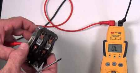
Connect the multimeter’s red lead to the ohm terminal and the black lead to the common terminal. Turn on the multimeter, then touch the leads together to confirm a 0-ohm reading.
To evaluate each line-to-terminal connection, place the red lead on L1 and the black lead on T1. A correct connection should show a 0-ohm reading. If the reading varies, it suggests an issue with that segment.
Engage the control switch to test the coil. The absence of an audible click could mean the coil is not receiving proper voltage or is defective.
To measure voltage, switch the multimeter to the voltage setting, placing the red lead to the volts terminal. Power the coil, and check each connector for the correct voltage. This step confirms the coil’s voltage integrity. If you're testing electric motors, visit our page on electric motor testing to explore diagnostic techniques that help detect insulation breakdown.
To evaluate the condition of the contactor coil, begin by removing all power from the system and disconnecting the coil wires. Set your multimeter to the resistance (ohms) setting.
Place one probe on each of the coil terminals.
A healthy coil should show a resistance value typically between 10 and 100 ohms, depending on the model and manufacturer specifications.
Readings below 10 ohms may indicate a shorted coil, while readings above 100 ohms (or infinite resistance) suggest an open or damaged coil.
This test helps confirm whether the coil is intact or needs replacement. Always refer to the equipment’s documentation for precise resistance values.
If the coil fails resistance tests, voltage is absent, or contacts are pitted or burnt, replacement is usually required. If continuity tests fail or the coil doesn’t engage with power applied, replace the contactor for safety and performance.
Think you know Electrical Testing & Maintenance? Take our quick, interactive quiz and test your knowledge in minutes.
After removing coil wires, switch the multimeter to the ohms setting. Place each lead on the coil’s connectors; the expected reading should fall between 10 to 100 ohms. A lower or higher reading indicates a potential defect in the coil.
If the testing reveals issues with the contactor or coil, replacing the faulty parts can restore the system’s reliability and efficiency. A functioning device ensures the electrical flow in air conditioning systems remains stable, supporting both performance and energy efficiency. Visit our NFPA 70B Testing and Maintenance Training course for more information.
Advantages To Instructor-Led Training – Instructor-Led Course, Customized Training, Multiple Locations, Economical, CEU Credits, Course Discounts.
Request For QuotationWhether you would prefer Live Online or In-Person instruction, our electrical training courses can be tailored to meet your company's specific requirements and delivered to your employees in one location or at various locations.