Latest Electrical Testing & Maintenance Articles
Industrial Electrical Maintenance Explained
Industrial electrical maintenance ensures the reliability of plant and factory power systems through regular inspections, testing, and repairs. It minimizes downtime, extends equipment life, improves safety, and prevents costly failures in critical industrial operations.
Industrial Electrical Maintenance Explained
NFPA 70B Industrial Electrical Maintenance Training
Electrical Testing and Troubleshooting Training
Request a Free Training Quotation
Industrial electrical maintenance plays a crucial role in ensuring the safety, efficiency, and reliability of industrial facilities. By understanding the key components of a testing and repair program, including preventive maintenance, troubleshooting, equipment maintenance, and the role of automation equipment, companies can develop a robust…
View more
Sign Up for Electricity Forum’s Electrical Testing & Maintenance Newsletter
Stay informed with our FREE Electrical Testing & Maintenance Newsletter — get the latest news, breakthrough technologies, and expert insights, delivered straight to your inbox.
Electrical Troubleshooting: Step-by-Step
Electrical troubleshooting is the process of diagnosing and fixing problems in power systems, circuits, or components. It involves testing, identifying faults, and restoring safe, reliable operation in residential, commercial, or industrial settings using specialized tools and expertise.
The Complete Guide to Electrical Troubleshooting
Visit Our Electrical Troubleshooting Training Course
It is a crucial skill for diagnosing and resolving energy issues in various systems. Whether it involves a tripped circuit breaker, faulty wiring, or malfunctioning equipment, this process saves time, enhances safety, and prevents further damage to power systems. Workers must be proficient in identifying and solving power faults, which…
View more
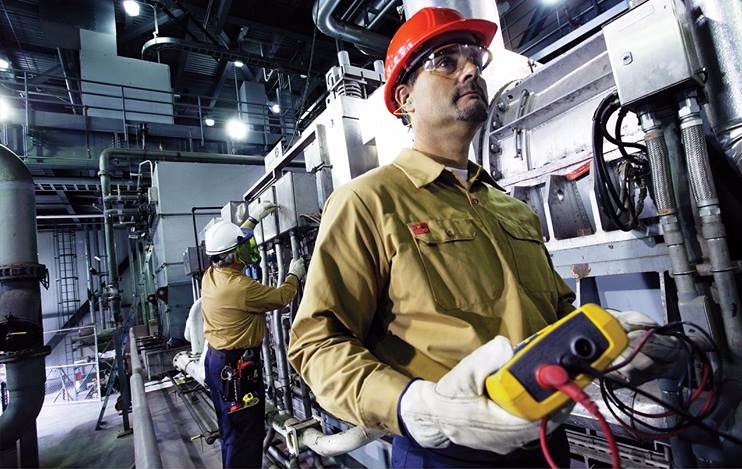
Electrical Testing Prevents Electrical Hazards
Electrical testing verifies safety, compliance, and performance through inspection, diagnostics, and calibration, including insulation resistance, continuity, earth testing, PAT checks, and power quality analysis for commissioning, preventive maintenance, and certification.
Electrical Testing Fundamentals
Electrical testing is a crucial aspect of maintaining safe and reliable power systems. It examines and evaluates equipment and installations to ensure they are functioning correctly, efficiently, and safely. This procedure is essential for various reasons, including protecting lives, property, and the environment and adhering to industry standards and guidelines. One of the critical components is assessing insulation resistance. This test measures the resistance of electrical insulation…
View more
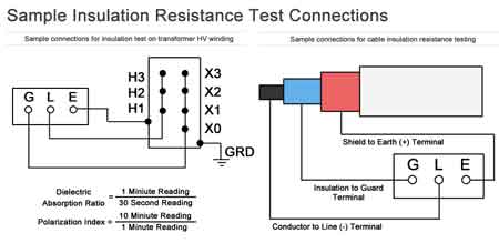
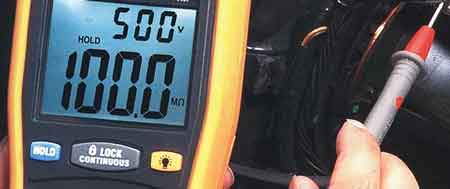
Checking Insulation Resistance
Checking insulation resistance ensures safe operation of electrical systems by detecting moisture, degradation, or leakage currents. It’s essential for preventing equipment failure and maintaining high dielectric quality in cables, motors, and switchgear.
A Practical Guide to Checking Insulation Resistance
Regular dielectric resistance testing is a crucial component of maintaining the integrity and safety of electrical insulation systems. This testing helps identify potential issues such as short circuits or degraded non-conductive material that could lead to failures. By performing these tests as part of a preventive maintenance routine, facilities can ensure that their systems operate efficiently and safely. To perform…
View more
What is Preventive Maintenance?
What Is Preventive Maintenance? A proactive approach for electrical systems using inspections, testing, lubrication, and calibration to reduce downtime, improve reliability, extend asset life, and meet NFPA 70B/IEC standards with CMMS-driven schedules and condition monitoring.
What Is Preventive Maintenance?
Preventive maintenance is a crucial aspect of equipment management that offers numerous benefits, including improved reliability, reduced downtime, and better asset management. By implementing a well-structured maintenance plan and leveraging available tools and software, organizations can optimize their operations and ensure the long-term success of their equipment maintenance programs. To build organizational capability, teams can leverage targeted preventive maintenance training…
View more
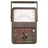
What is a Megohmmeter? A Great Testing Tool
What is a megohmmeter? An insulation resistance tester that applies high DC voltage to measure gigaohms, detect leakage current and dielectric integrity in cables, motors, transformers, and switchgear for safety, commissioning, and preventive maintenance.
What Is a Megohmmeter?
What is a megohmmeter, and why should every electrical professional understand its importance? This specialized tool, also known as an insulation resistance tester, is critical for ensuring the safety and reliability of electrical systems in industrial, commercial, and institutional settings. By measuring high resistance values in electrical insulation, it helps detect potential faults, prevent equipment failures, and minimize costly downtime. In…
View more

Data Logger Explained
Data logger for electrical engineering applications, enabling data acquisition from sensors, high-resolution measurement, time-series recording, telemetry, calibration, and IoT monitoring for power quality, energy metering, equipment diagnostics, and load profiling.
Data Logger Overview and Best Practices
A data logger (or sometimes called a "datalogger") is a specialized electronic device that measures and records specific data over a certain period of time or in relation to its location either with a built-in instrument or sensor or via external instruments and sensors.Datalogging is a term used to describe using a device to collect data through a sensor. That way, the data can be analyzed and saved…
View more