Transformer Grounding Diagram Explained
By Frank Baker, Technical Editor
By Frank Baker, Technical Editor
Our customized live online or in‑person group training can be delivered to your staff at your location.

A transformer grounding diagram illustrates safe electrical connections, including grounding methods, fault-current paths, and protective bonding. It improves safety, stability, and code compliance in power systems across utility and industrial settings.
Transformer grounding diagrams visually represent how transformer grounding behavior connects the neutral point, fault paths, and earth reference.
A transformer grounding diagram is a critical tool used in the design, installation, and maintenance of electrical systems. It provides detailed information on how a transformer is grounded to protect both the system and personnel from electrical faults. Proper grounding (sometimes called "earthing") ensures that the system's neutral point is stabilized, which is essential for preventing damage and enhancing system reliability. This article examines the role of a grounding diagram, its benefits during installation, and the potential problems it helps identify. Understanding a transformer’s basic design is the first step before studying grounding diagrams, since earthing methods depend on how windings and cores are constructed.
Electrical Transformer Maintenance Training
Substation Maintenance Training
Request a Free Training Quotation
A grounding diagram serves a clear purpose: to demonstrate the configuration of the earthing system. Grounding controls fault currents when a ground fault occurs, directing the current safely into the earth while stabilizing system voltage by holding the neutral point at ground potential. In high-voltage systems, this function is indispensable. A well-drawn grounding diagram allows engineers to predict system performance during faults within the grounding system architecture that organizes reference and fault control.
In one real-world example, an industrial facility with a 13.8 kV substation experienced damaging neutral overvoltages. Reviewing the grounding diagram revealed an undersized earthing conductor. Once corrected, neutral voltages dropped dramatically during faults, preventing relay misoperations and ensuring compliance with IEEE Std. 142, known as the Green Book. When specifying equipment, transformer grounding diagrams should be reviewed alongside transformer sizing calculations to ensure electrical performance and safety compliance.
Stay informed with our FREE Electrical Transformers Newsletter — get the latest news, breakthrough technologies, and expert insights, delivered straight to your inbox.
Like any part of an electrical system, earthing can suffer from weaknesses that a diagram helps identify. Poor connections at the neutral point, incorrectly sized conductors, or failures in earthing transformers within ungrounded systems can all create instability and hazards. Improper earthing often leads to elevated voltages, increasing the risk of equipment failure. Engineers commonly use calculation checks to avoid these pitfalls. For example, when sizing a neutral grounding resistor, the fault current is determined using the formula:
I = V / R
where I is the fault current, V is the line-to-neutral voltage, and R is the chosen resistance. Selecting improper values may result in dangerously high fault currents or ineffective protection. In distribution networks, earthing is critical for single phase transformer connections, ensuring system stability and reducing the risk of neutral shift.
Every transformer grounding diagram shares certain key components. These include the neutral point where transformer windings connect to ground, the grounding electrode itself, and the conductors that form the fault current path, including the grounding electrode conductor.
In delta-connected systems, the diagram often shows an earthing transformer—such as a zigzag configuration—that provides a return path for ground faults when a direct neutral is not present. Technicians use these diagrams not only to ensure correct installation but also to verify the system's condition during periodic maintenance. Industry standards such as NEC Article 250 and IEEE Std. 81 recommends testing methods, including fall-of-potential and clamp-on ground resistance tests, often with a goal of less than 25 ohms, or, for critical substations, where substation grounding practices require very low resistance values. For power quality and protection, instrument transformers rely on correct earthing of secondary windings to prevent dangerous overvoltages.
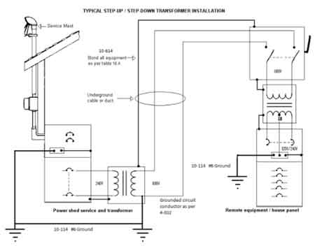
![]()
One of the two output conductors can be connected to ground, designating it as the neutral, while the other remains the energized line.
There are several grounding configurations that engineers may select, and diagrams help distinguish their applications. Solid grounding directly connects the neutral to earth, creating a low-impedance path that ensures fast fault clearing but results in high fault currents. Resistance earthing, whether low or high impedance, introduces a resistor between neutral and ground, thereby limiting fault currents to safer levels. High-resistance grounding, in particular, is effective at reducing arc-flash hazards but requires careful insulation coordination. Zigzag earthing transformers, commonly applied to delta systems, provide a path for zero-sequence currents while maintaining balanced voltages.
Each method carries its own benefits and limitations:
Solid grounding enables fast fault clearing but can produce destructive current magnitudes.
Low-resistance grounding provides balance by allowing fault detection with limited current.
High-resistance grounding minimizes current and arc energy but requires upgrades to system insulation.
Zigzag grounding offers flexibility in ungrounded systems, providing a fault current path without altering voltage balance.
Engineers also review earthing considerations when installing dry type transformers, especially in indoor locations where insulation and fault paths must be tightly controlled.
| Grounding Method | Advantages | Disadvantages | Typical Applications |
|---|---|---|---|
| Solid | Fast fault clearing; stable voltage reference | High fault current can damage equipment | Utilities, high-voltage transmission |
| Low-Resistance | Limits current while allowing detection; protects equipment | Resistors require maintenance; moderate fault currents remain | Industrial distribution systems |
| High-Resistance | Reduces arc flash risk; minimizes equipment stress | Requires higher insulation; limits fault detection sensitivity | Sensitive process plants, mining, and data centers |
| Zigzag Grounding Transformer | Provides a path for zero-sequence currents in delta systems; maintains voltage balance | Added cost and complexity; not needed if neutral is already available | Delta-connected systems, substations |
Beyond initial installation, grounding diagrams play an important role in maintenance. They help technicians trace connections, verify the integrity of earthing, and plan inspections of conductors and electrodes. For example, clamp-on resistance testers can confirm whether bonding conductors remain intact, while step-and-touch potential measurements can identify dangerous ground voltage gradients. These checks help detect weaknesses before they evolve into failures. Proper earthing is critical to the accuracy of a current transformer, as any imbalance in the fault return path can distort measurement signals. In low-voltage control circuits, a control transformer often requires careful earthing practices to prevent nuisance faults and ensure safe operation of sensitive equipment.
Grounding diagrams also act as tools for anticipating risks. If a delta system is shown without a grounding transformer, this may indicate that no proper return path for ground faults exists. Such omissions can lead to transient overvoltages, ferroresonance, or neutral shift, all of which increase stress on transformer insulation and protective devices. IEEE Std. C62.92 notes that poorly configured earthing systems may even amplify switching surges. By identifying these risks in the design phase, diagrams help prevent downtime, damage, and hazards.
Download our FREE Electrical Training Catalog and explore a full range of expert-led electrical training courses.

Ultimately, a transformer grounding diagram is more than a schematic—it is a safeguard for safe and efficient operation. It documents how the transformer is connected to ground, provides installation reference, and guides maintenance practices throughout the system’s life. By ensuring proper earthing, these diagrams stabilize system voltage, control fault currents, and safeguard personnel and equipment. When integrated with proper testing, adherence to NEC, IEEE, and IEC standards, and ongoing maintenance, grounding diagrams become a cornerstone of electrical safety engineering.
Explore 50+ live, expert-led electrical training courses –