Power Factor Calculation
By R.W. Hurst, Editor
By R.W. Hurst, Editor
Our customized live online or in‑person group training can be delivered to your staff at your location.


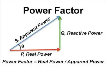
Power factor calculation determines how effectively an AC electrical system converts supplied power into useful work by comparing real power to apparent power.
The governing equation is PF = kW / kVA, and in sinusoidal systems it is also expressed as PF = cos φ, where φ is the phase angle between voltage and current. In practice, true power is measured in kW, apparent power in kVA, and reactive power in kVAR. These values show how much of the current drawn by a load produces useful output and how much circulates as reactive demand.
Poor power factor increases current for the same kW load, which raises conductor heating, transformer loading, voltage drop, and utility penalty exposure. A facility may appear stable from a demand standpoint while still wasting capacity and stressing equipment because the system is carrying unnecessary reactive current.
That is why power factor calculation is used in troubleshooting, capacitor correction, transformer and feeder sizing, VFD application review, and load studies. When engineers calculate power factor correctly, they can determine whether poor performance is due to inefficient real power use or to excess apparent power caused by phase displacement and reactive loading.
Power factor calculation is a field diagnostic used to determine whether an electrical system is using current efficiently under actual operating conditions. It is a practical diagnostic method used to determine whether an electrical system is using capacity efficiently under actual operating conditions. By comparing watts, volt-amperes, and phase angle behavior, technicians can identify where current demand is rising without a corresponding increase in useful output.

In AC systems dominated by motors, transformers, and other inductive equipment, reactive demand increases current while real power remains unchanged. That condition lowers PF, increases electrical stress, and reduces usable system capacity. A clear understanding of Power Factor helps explain why two systems with the same kW demand can impose very different burdens on conductors, breakers, and upstream equipment.
Improving PF is ultimately about reducing avoidable current, protecting equipment, and maintaining better power quality under load. For that reason, PF calculation is used not only in analysis but also in correction planning, equipment evaluation, and operating-cost control.
For calculation purposes, power factor is the ratio of real power to apparent power:
PF = kW / kVA
Because apparent power is always equal to or greater than real power, measured PF values fall between 0 and 1. A value near 1 indicates that most of the supplied current is producing useful work. Lower values indicate that more current is flowing to support magnetic or electric fields rather than to deliver output.
This distinction matters because electrical equipment is often limited by current and kVA, not by kW alone. A low PF can therefore consume feeder and transformer capacity long before real power demand appears excessive.
Power factor calculation becomes more meaningful when the actual load type is considered. Resistive heaters typically operate near unity PF because nearly all supplied current is converted directly into useful heat. Motors usually produce lagging PF because they require magnetizing current. VFDs, switched-mode power supplies, and other non-linear loads can distort the current waveform and reduce true PF even when displacement PF appears acceptable.
PF also changes with operating conditions. A lightly loaded induction motor may exhibit poor PF, which improves as the motor approaches rated output. In mixed commercial and industrial systems, PF can shift throughout the day as motors, lighting, HVAC systems, and electronic loads cycle on and off.
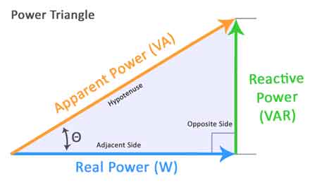
The power triangle provides a useful structure for interpreting PF calculations. Real power (P) lies on the horizontal axis, reactive power (Q) rises vertically, and apparent power (S) forms the diagonal.
Once two values are known, the third can be determined. The angle between real power and apparent power is the phase angle φ, and PF can be calculated either from the ratio of real to apparent power or from the cosine of that angle.
This relationship is important in field analysis because it connects measurement data to system behavior. When technicians compare kW, kVA, and kVAR readings, they are not just solving a formula. They are determining how much of the current demand is productive and how much is reactive.
Consider a system delivering 5 kW of real power while drawing 6 kVA of apparent power:
PF = 5 ÷ 6 = 0.83
A PF of 0.83 indicates that the installation requires more current than a purely real load delivering the same output. That extra current increases heating in conductors, raises transformer loading, and reduces the spare capacity available elsewhere in the system.
When measured voltage and current are used to derive apparent power, tools such as an apparent power calculator or the apparent power formula help verify that the kVA value used in the PF calculation is correct.
Stay informed with our FREE Power Quality Newsletter — get the latest news, breakthrough technologies, and expert insights, delivered straight to your inbox.
Load factor and power factor both influence electrical performance, but they measure different aspects of it. PF is the instantaneous ratio of real power to apparent power at a given operating point. The load factor compares the average demand over time to the peak demand.
A facility can have acceptable PF during peak operation and still use its electrical infrastructure inefficiently over the billing period if the load factor is low. Conversely, a plant with a high load factor may still experience continuous reactive waste if PF remains poor. Looking at both values together gives operators a more complete picture of capacity use and operating efficiency.
When PF calculations show that reactive demand is unnecessarily high, correction becomes a practical next step. Capacitors are commonly applied because they supply leading reactive current locally, reducing the reactive current that must be delivered by the source.
The required capacitance depends on voltage, frequency, and the amount of reactive
Explore 50+ live, expert-led electrical training courses –