Latest Generators/UPS Articles
How long do battery backups last?
Battery backups typically last between 3 and 10 years, depending on type, usage, and maintenance. UPS systems, backup batteries, and power storage units degrade over time due to temperature, charge cycles, and environmental factors affecting lifespan and reliability.
How long do battery backups last?
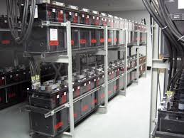
Battery backup systems, pivotal for a continuous power supply, are integral in mitigating the impact of power outages in residential, commercial, and industrial environments. These systems, also known as uninterruptible power supplies (UPS), provide a critical safeguard against data loss and operational downtime. Understanding their lifespan, operational dynamics, and maintenance needs is vital for optimizing…
View more
Sign Up for Electricity Forum’s Generators/UPS Newsletter
Stay informed with our FREE Generators/UPS Newsletter — get the latest news, breakthrough technologies, and expert insights, delivered straight to your inbox.

Understanding Your UPS Power Supply - Uninterruptible Electricity
UPS power supply ensures uninterruptible power, voltage regulation, and surge protection with battery backup, inverter, and AVR, delivering clean sine-wave output for servers, networking gear, and industrial controls during outages and brownouts.
UPS Power Supply Fundamentals
WHAT IS A UPS POWER SUPPLY?An Uninterruptible Power Supply (UPS) System is a device that supplies battery backup power to computers and peripherals during short power outages, and allows systems to safely shutdown during prolonged blackouts. UPS systems also correct brownouts and overvoltages, stop damaging power surges and filter disruptive line noise. An Uninterruptible Power Supply system sits between a power supply (e.g. a…
View more
Automatic Transfer Switch
An automatic transfer switch (ATS) seamlessly shifts electrical load from the utility to a backup generator during power outages. It ensures continuous power, improves safety, and protects sensitive equipment from unexpected power loss or fluctuations.
How an Automatic Transfer Switch Works
Emergency Generator Standby Power Training
Power Quality Analysis Training
Request a Free Emergency Generator Training Quotation
Technical Depth: Controllers and Monitoring Logic
Modern automatic transfer switches rely on intelligent control systems to ensure seamless and safe operation during power outages. These controllers are the "brains" of the automatic transfer switch, constantly monitoring utility and generator power for…
View more

UPS Risks - Surge Protection For Critical Loads
UPS risks include battery failure, overload, harmonics, thermal stress, poor grounding, EMI/RFI, and inadequate maintenance, leading to downtime, reduced power quality, inefficiency, and safety hazards in critical electrical systems operations.
Basics of UPS Risks in Electrical Engineering
The use of computers and other electronic systems has skyrocketed, and with it, so has the need to protect these systems from damage and service interruptions. Uninterruptible and stand-by power systems were created to fill the gap when sudden power disturbances threaten the operation of electronic equipment. However, there is a general is conception that UPS systems offer adequate protection against all…
View more
UPS Uninterruptible Power Supply
UPS Uninterruptible Power Supply systems provide backup power, voltage regulation, and surge protection to protect data centers, servers, and sensitive electronics from blackouts, outages, and harmful power disturbances that threaten essential equipment.
How a UPS (Uninterruptible Power Supply) Works
UPS System Training
Emergency Generators and Standby Power Training
Request a Free Training Quotation
In today's technology-driven world, protecting sensitive electronic equipment from outages and power fluctuations is of utmost importance. An uninterruptible power supply (UPS) plays a crucial role in ensuring the safety and smooth operation of your devices. This article aims to provide an in-depth understanding of UPS systems,…
View more
Emergency Generator Explained
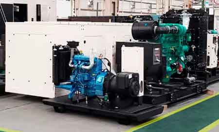
An emergency generator provides backup power during outages, protecting critical loads in hospitals, data centers, and industrial facilities. It starts automatically to keep lights and systems on, improving safety, reliability, and resilience when utility power fails.
Emergency Generator Fundamentals
Emergency Generator Standby Power Training
Power Quality Analysis Training
Request a Free Emergency Generator Training Quotation
It provides essential backup power when the grid goes down, keeping critical systems online. Many standby generators operate on natural gas, offering a reliable fuel supply without the need for storage. Paired with an automatic transfer switch, these systems instantly detect outages and seamlessly…
View more
How Does a Generator Work?
A generator works by using electromagnetic induction to convert mechanical energy into electricity. A rotor spins inside a stator, creating current, while a voltage regulator ensures stable output for homes, businesses, and industrial use.
Understanding the Generator
A generator is a device that converts mechanical energy into electrical energy by using an engine or turbine to rotate a rotor inside a stator. As the rotor spins, it creates a changing magnetic field that induces an electrical current in the stator windings. This generated alternating current is then regulated and delivered for use in residential, commercial, and industrial electrical systems.…
View more